Week 3: Embedded Programming
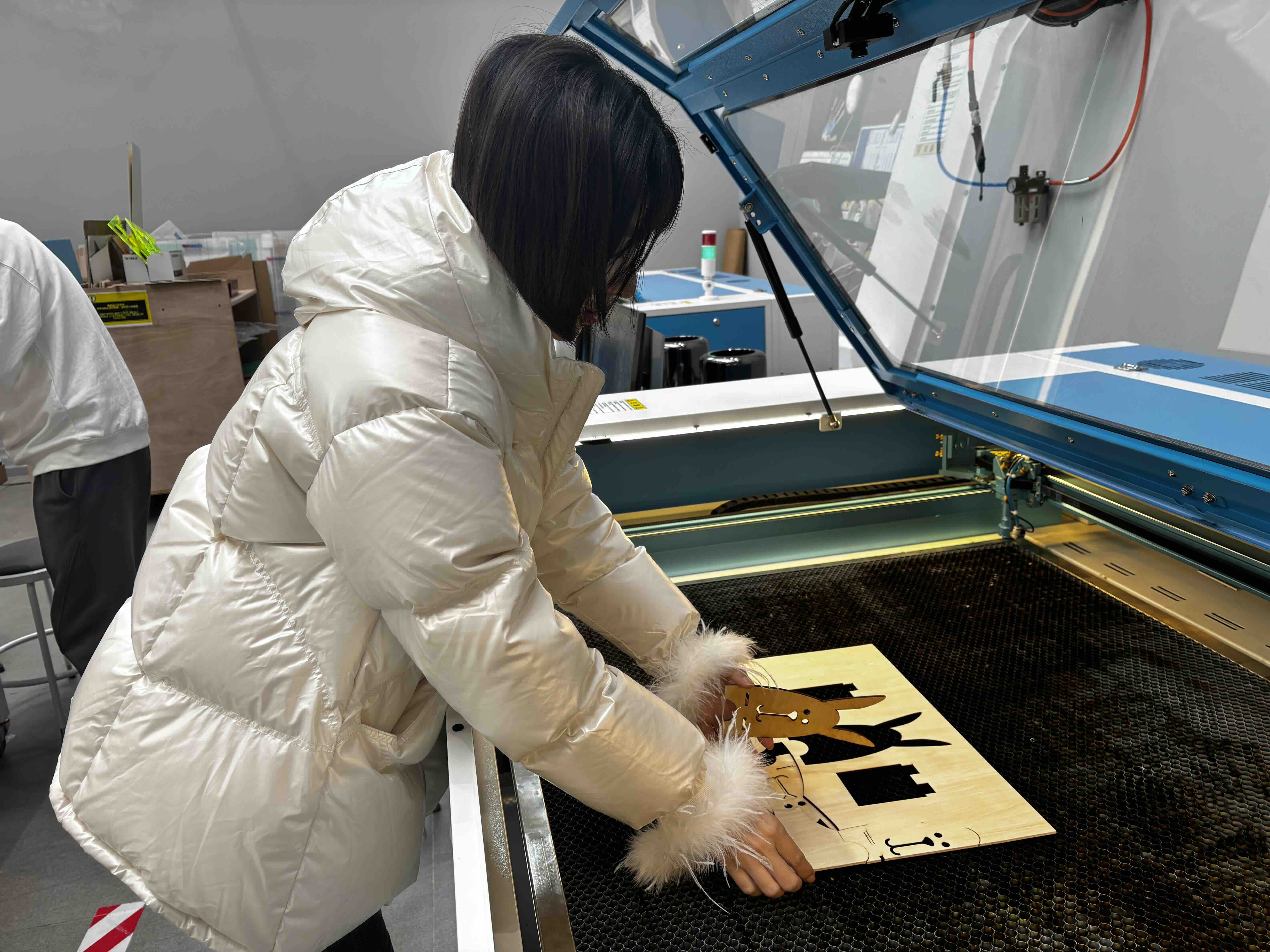
This week I learned how to use the Thunder Laser Cutting-NOVA 24 to make a phone stand.
Week 3 Group Work
Team collaboration: test the laser cutter tolerances
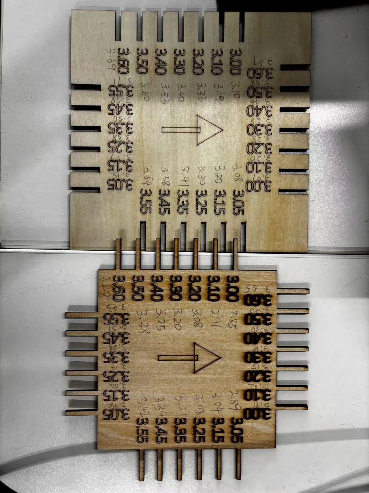
1.Design a tolerance test gauge in a 2D software
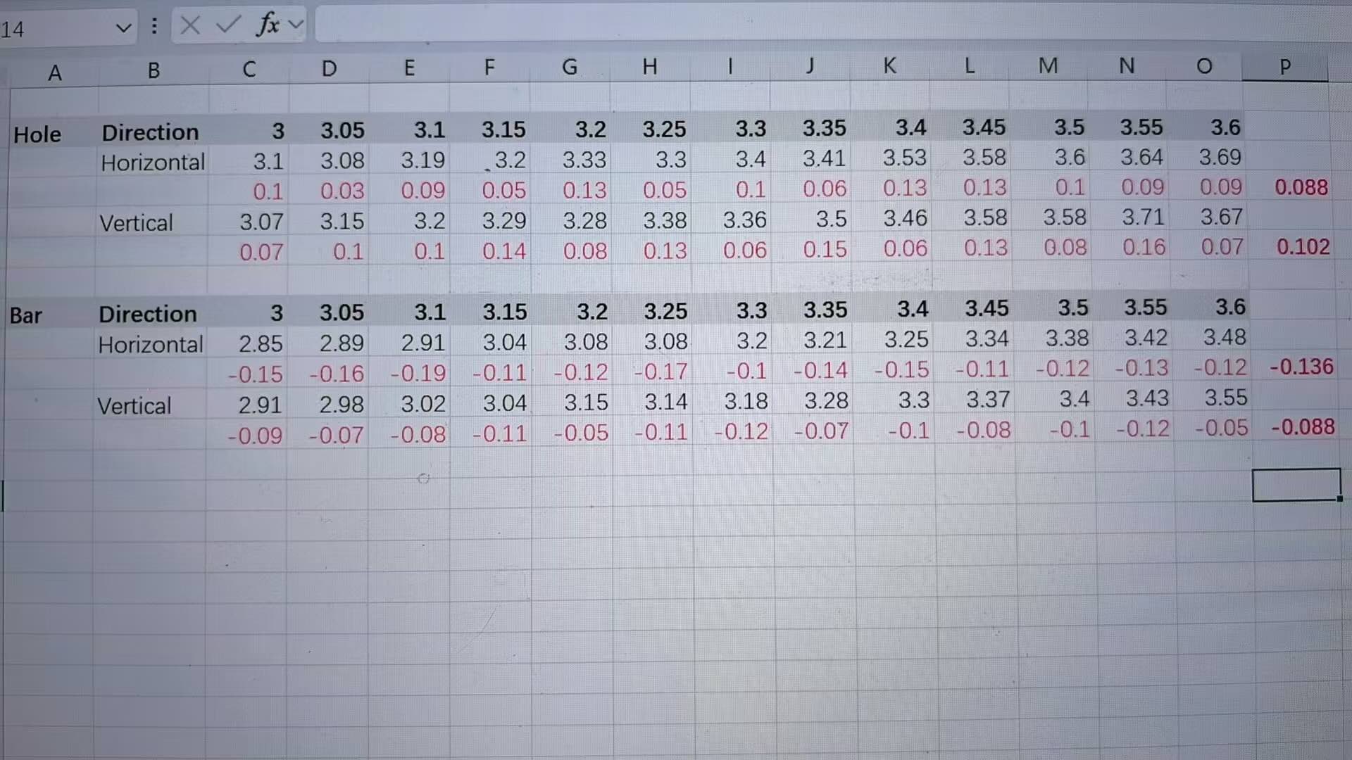
2. Export the file and send it to the laser cutter for cutting, then measure how the machine performs at different dimensions
3. Identify the minimum gap that the laser cutter can cut accurately
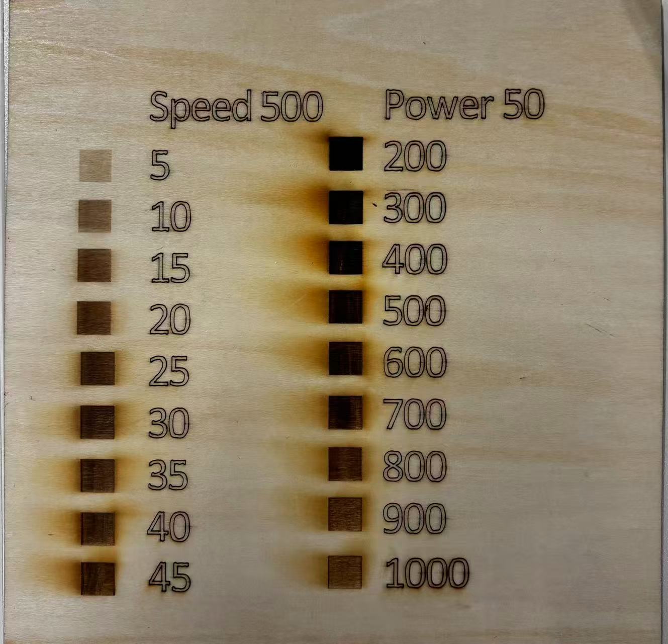
4. Adjust laser cutting parameters to achieve the best cutting results (power, speed, etc.)Document the process from designing the test gauge to obtaining the optimal results
Reflection of what I learned
This week, I learned how to use the Thunder Laser Cutting-NOVA 51 to make a phone stand.
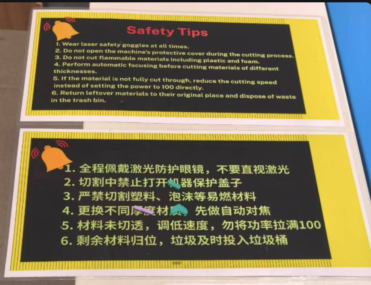
While using the laser cutter, I learned the safety rules and how to use the laser cutter safely. Here are a few key takeaways.
Design a phone stand using LaserMaker software based on the tolerance tested in the groupwork.
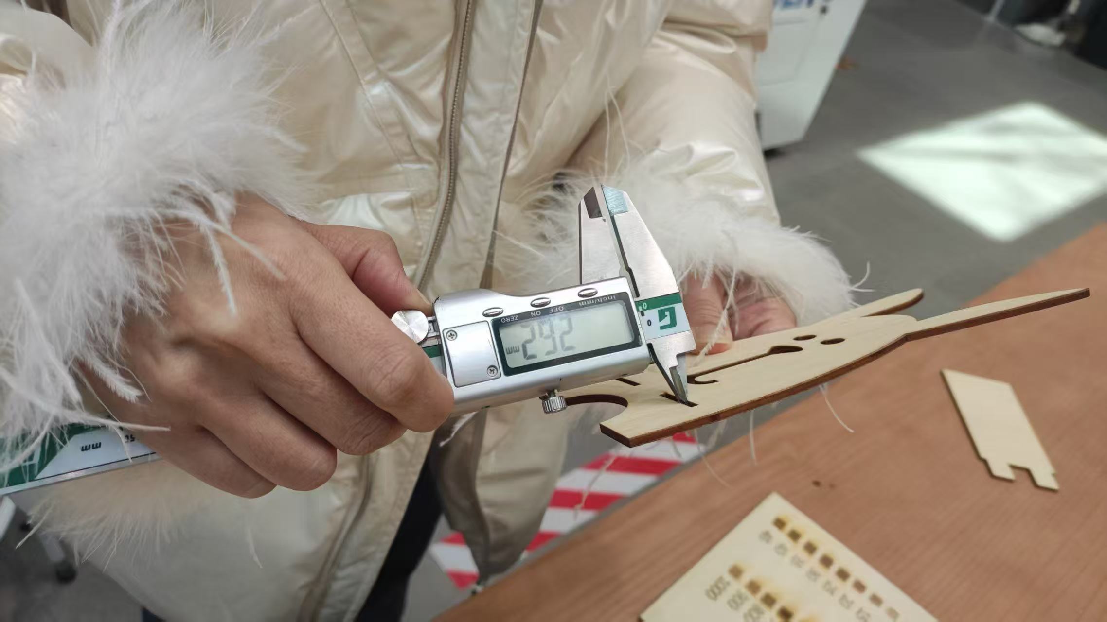
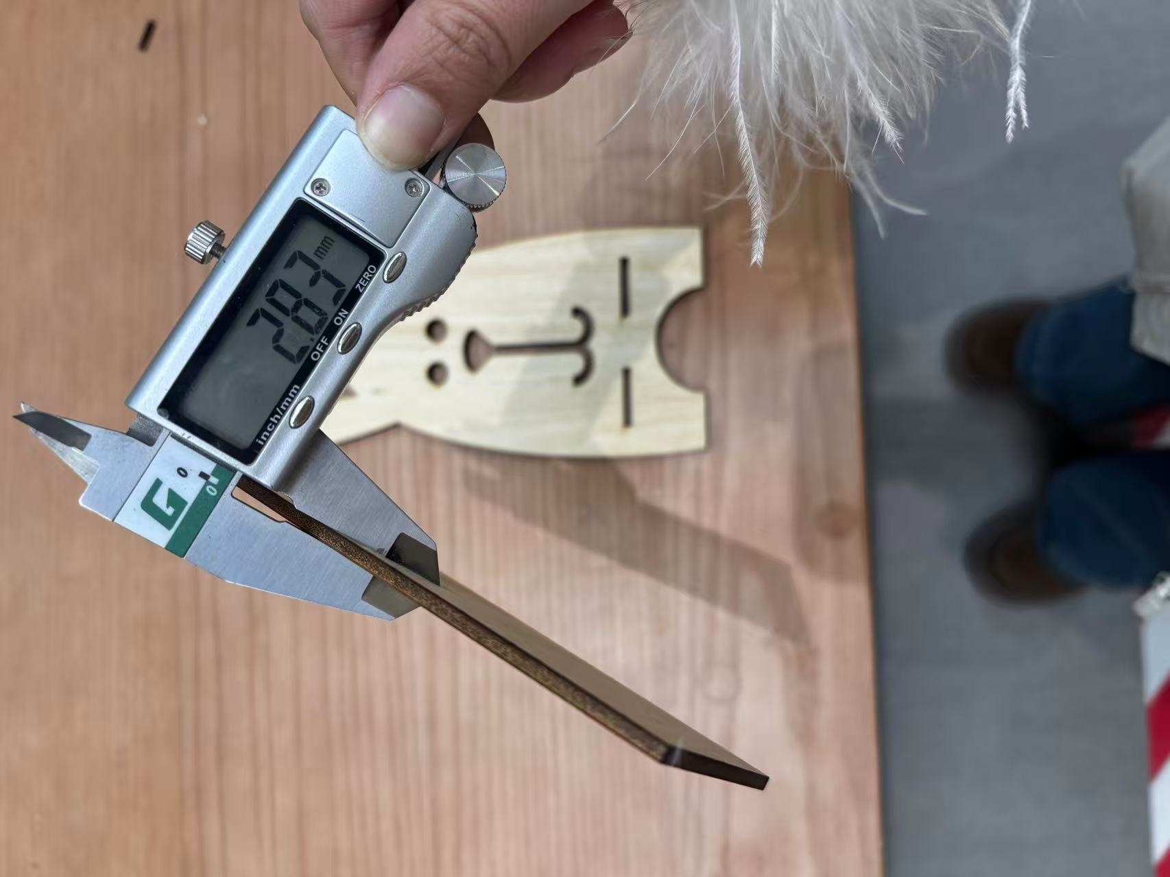
I tested the tolerance of the laser cutting machine with my team members using different sizes of holes and bars, both horizontally and vertically. I performed the laser cutting twice due to the machine’s tolerance issues, and as a result, the plywood could not be inserted into the socket holes at the first time. The second time, the width was adjusted from 2.9mm to 3.2mm, so that the plywood could fit into the socket hole properly.
- We should always wear the laser safety goggles at all times when operating the laser cutter.
- There is a camera on the laser cutter. After the laser cutting is completed, we can check the cutting results by watching the camera. Do not move the board until the laser cutting is completed.
- After the laser cutting is completed, we should wait for the board to cool down for a few minutes before removing it from the laser cutter.
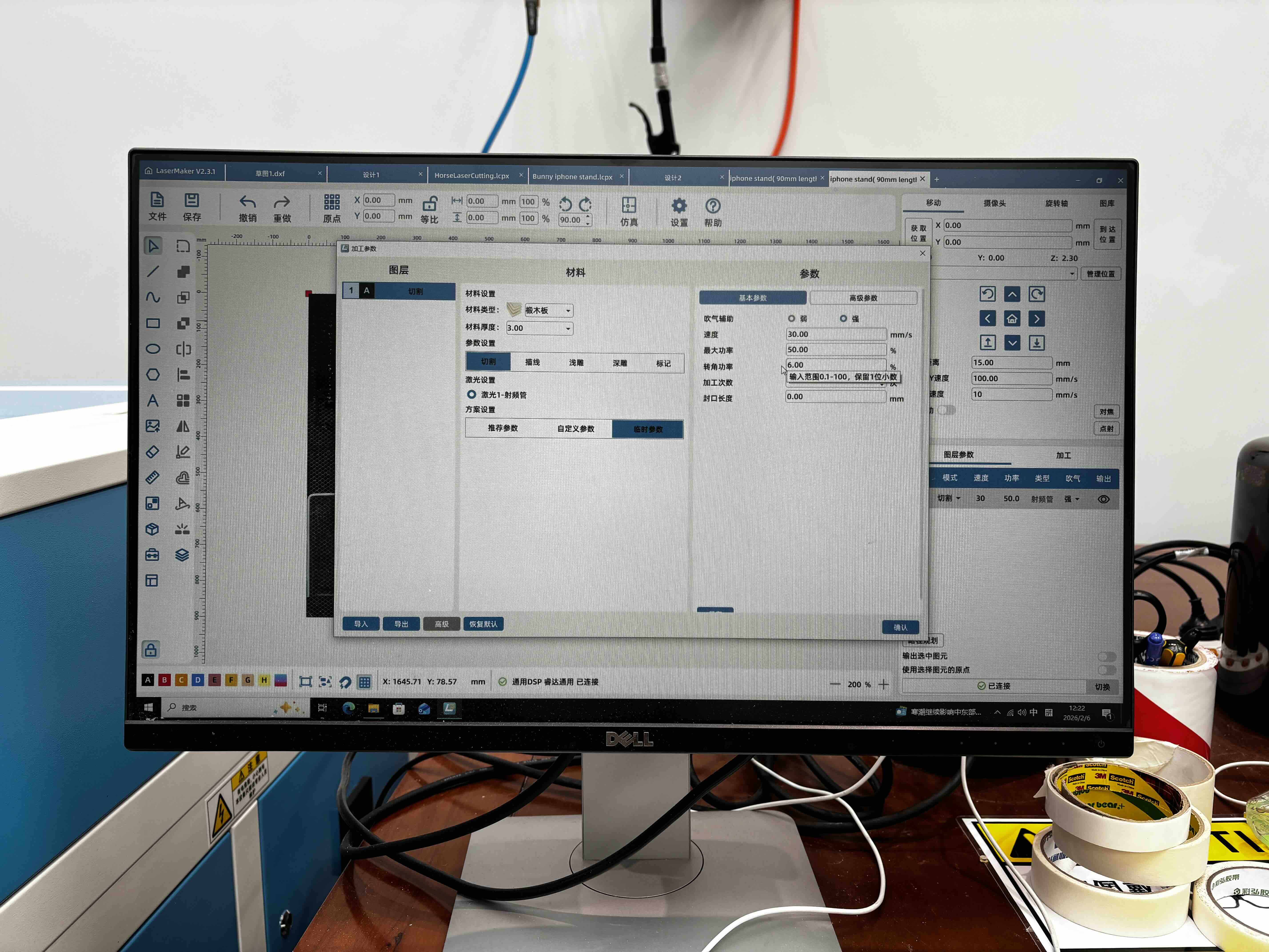
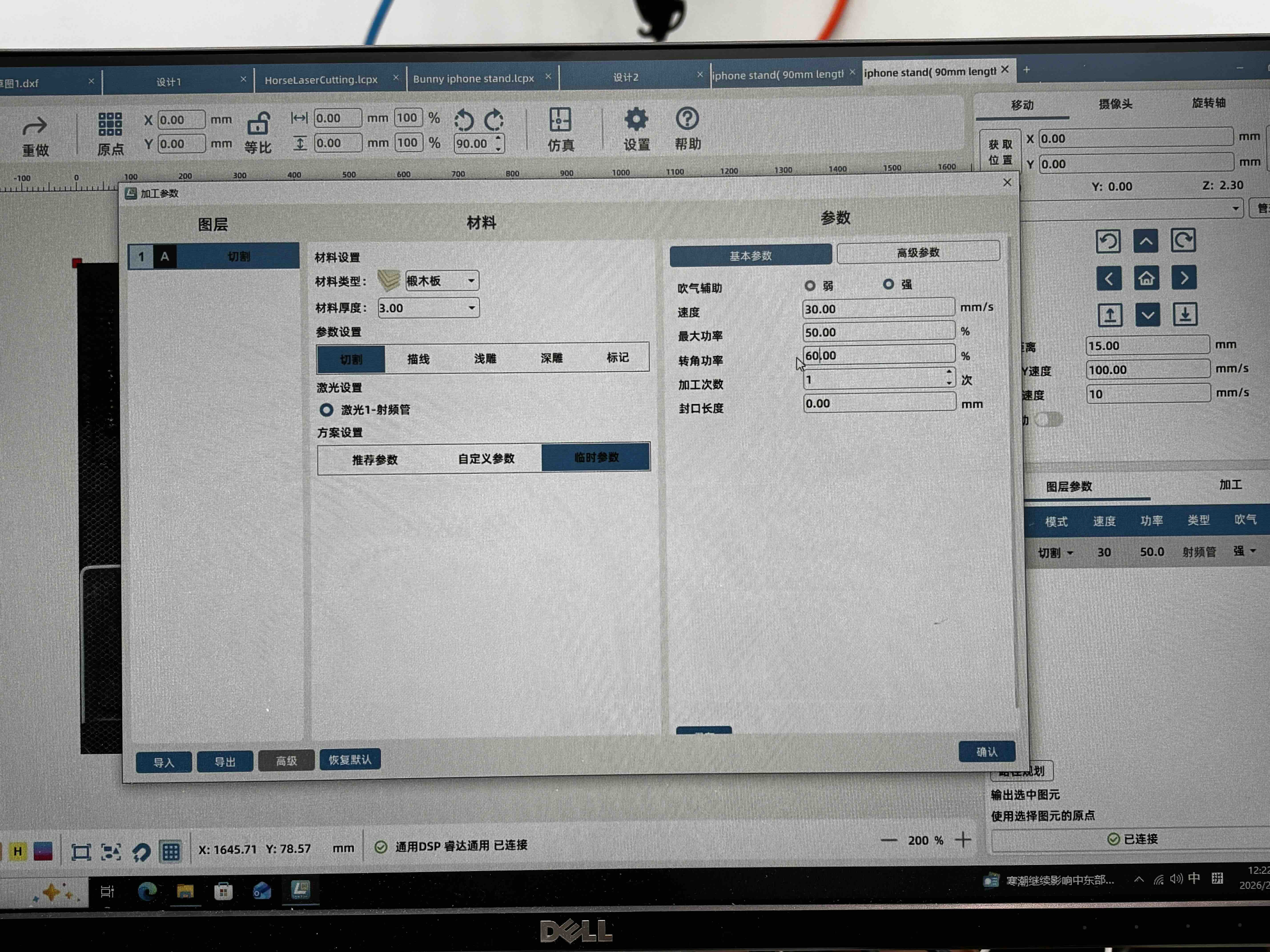
- A higher speed is not always better; we should choose the appropriate speed for the material. When cutting a corner, if the speed is too fast it can cause excessive charring that weakens the wood fibres. When setting the parameters, the angular power should be tested at about 60% of the total power.
About the safty training:
Safety Training
- Inspect the machine – Check for any damage, loose cables, or debris inside.
- Check ventilation – Ensure exhaust/fume extraction is working to remove hazardous fumes.
- Use approved materials only – Never cut PVC, vinyl, ABS, polycarbonate, or reflective metals (e.g., bare copper, brass) – they release toxic gas or damage the laser. Use wood, acrylic, paper, cardboard, or manufacturer‑approved materials.
- Focus correctly – Set the correct focal distance for the material thickness.
- Close the lid – Always operate with the protective cover fully closed.
- Wear laser safety goggles at all times when operating the laser cutter.
- Fire extinguisher location — a CO₂ extinguisher is mounted next to the machine; never use a water extinguisher near electrical equipment.
- Know the emergency stop — the big red button on the machine immediately halts the laser and the motion system.
Individual Assignment
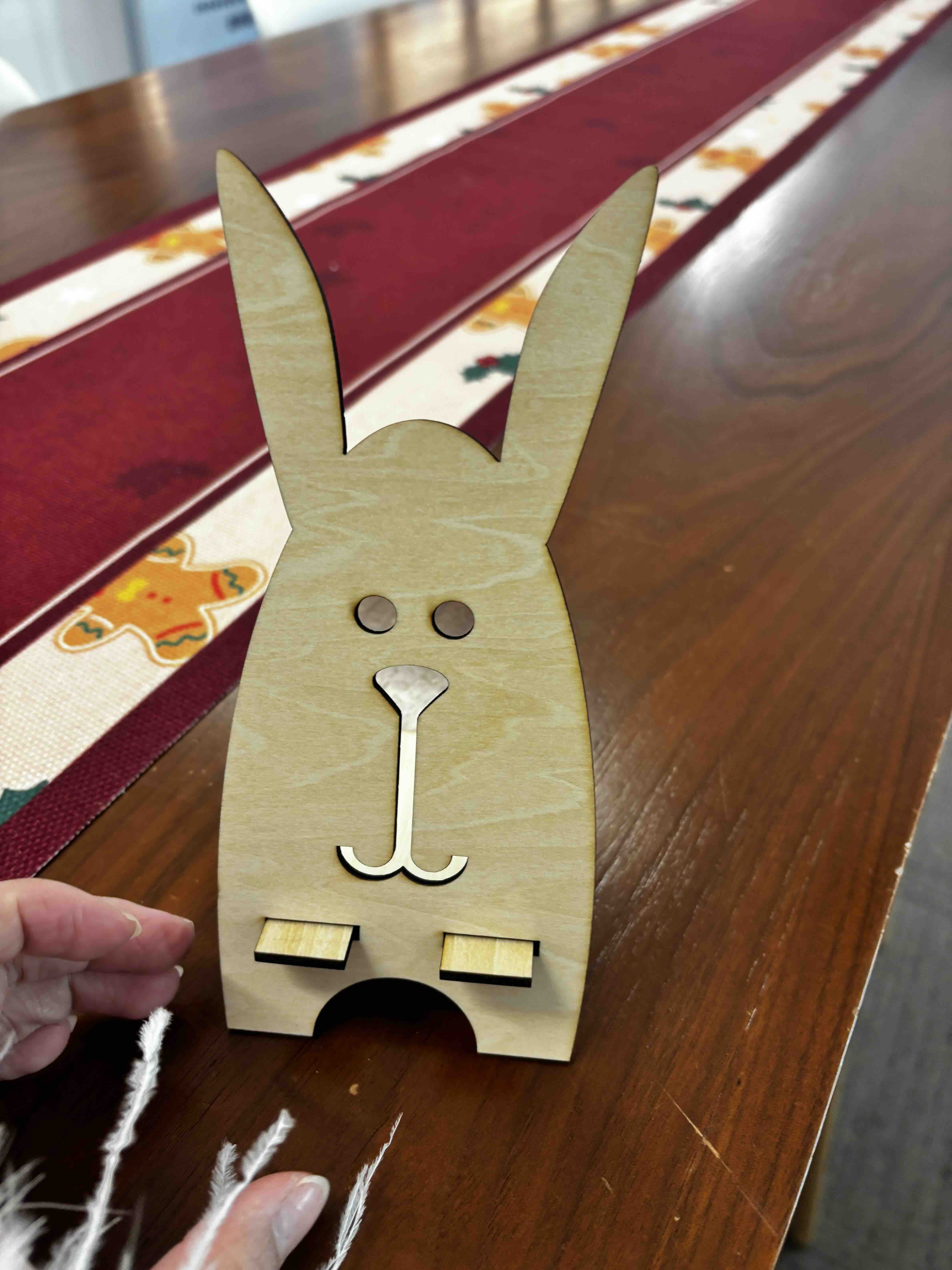
This week, I designed a phone stand and made a press-fit constrciton kit by using the laser cutter. Also explored the parametric design using Fusion 360.
Parametric design using Fusion 360
What are parameters in Fusion
Parameters in Fusion are predefined values — such as length, width, or hole count — that control features and dimensions throughout your model. These values can function as single numeric values, equations, or variables tied to other parameters. Whenever a parameter changes, every dependent feature updates instantaneously, saving hours of manual rework and minimizing the risk of human error.
Why use parametric design?
Parameters in Fusion are essential for making designs more efficient and adaptable. Whether controlling basic dimensions or managing complex relationships between parts, parameters in Fusion automate key aspects of the modeling process. Using operators, functions like floor and round, and conditional statements, you can create responsive models that adapt easily to changes. Additionally, configurations allow you to manage multiple design versions without rebuilding from scratch.
How to create parameters in Fusion
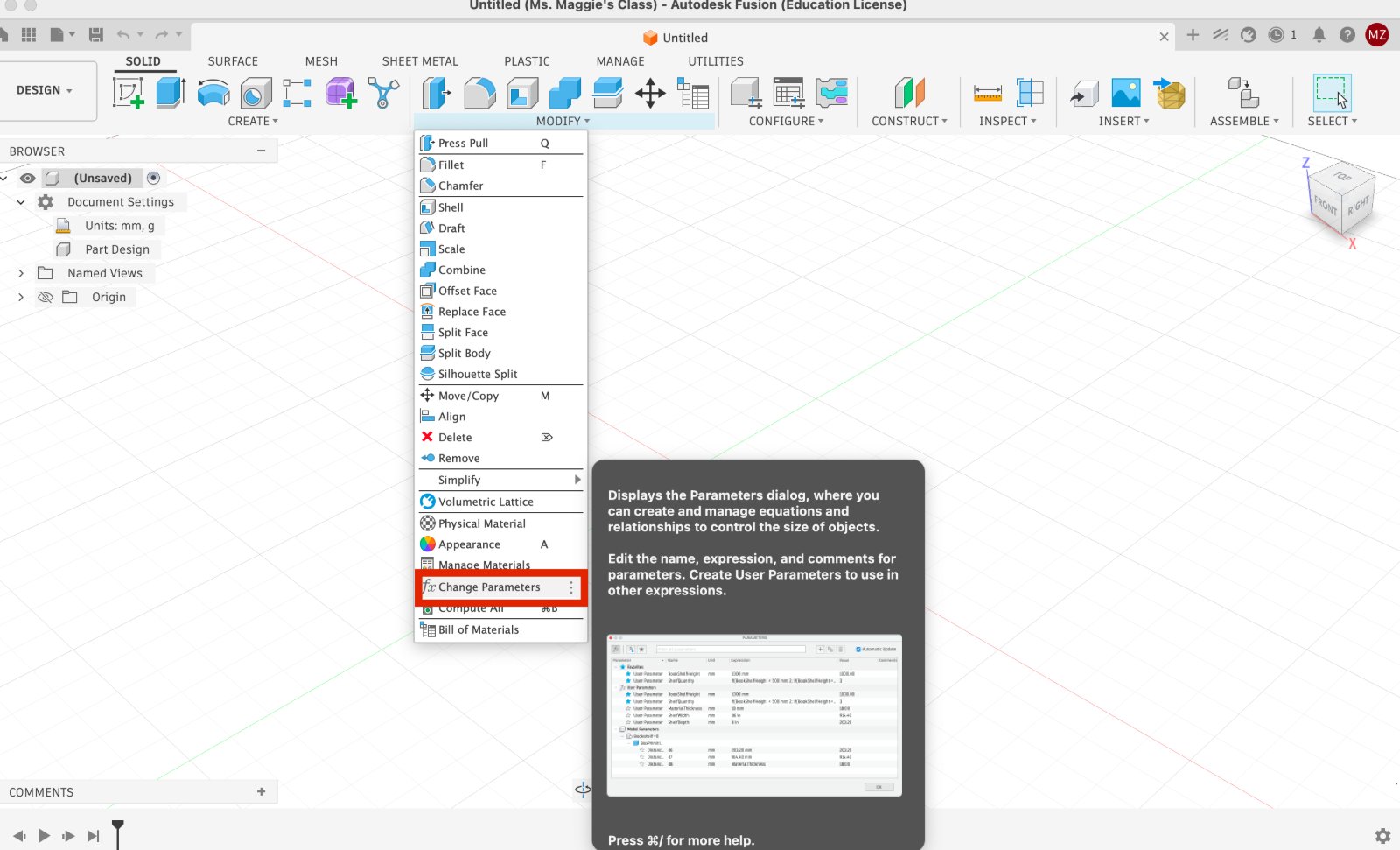
- Access the parameters dialog: To get started, navigate to the Design workspace and go to Modify > Change Parameters
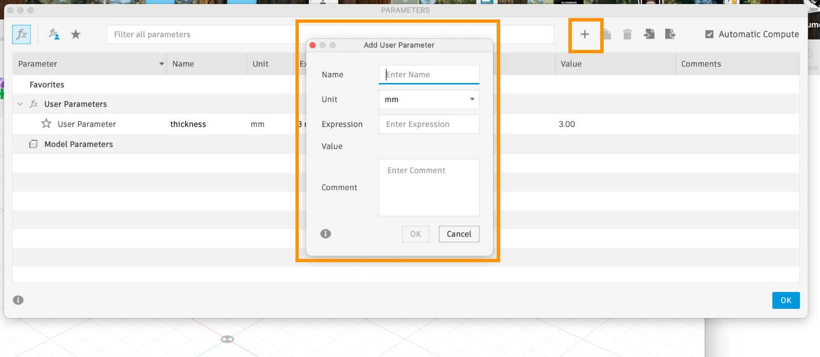
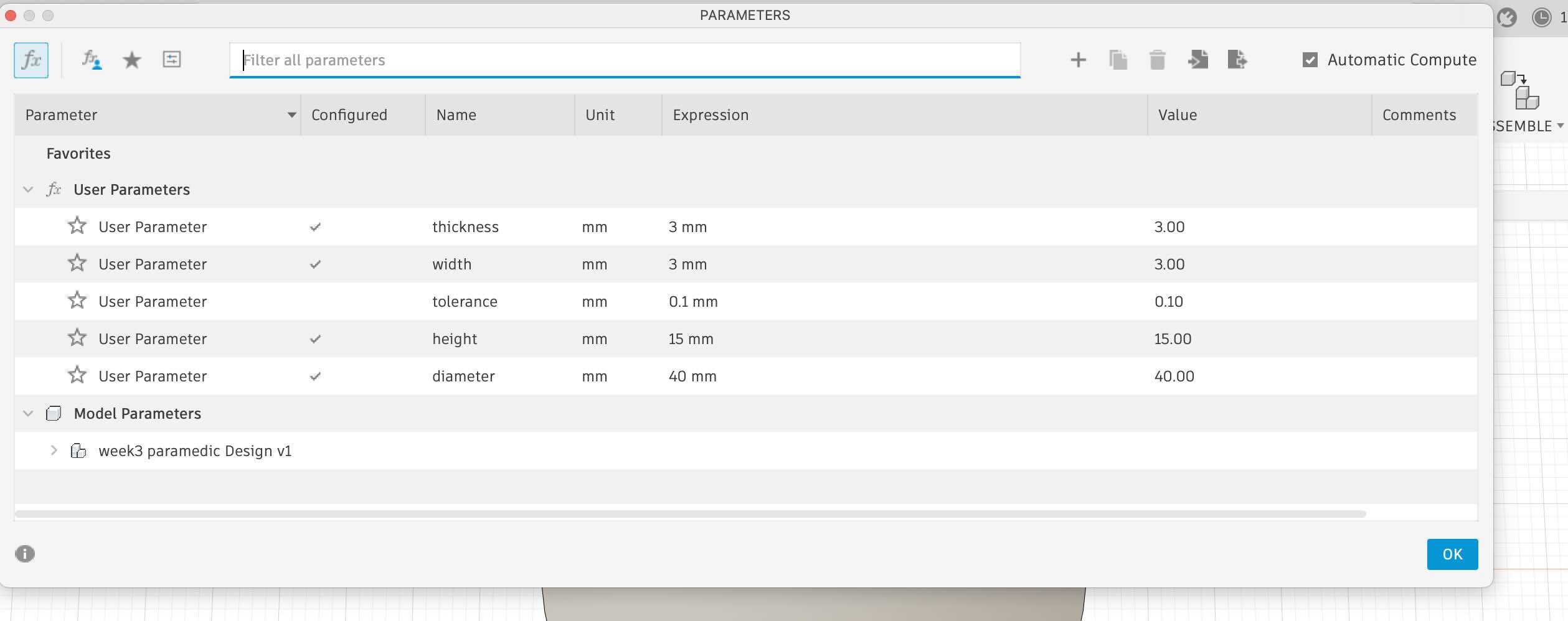
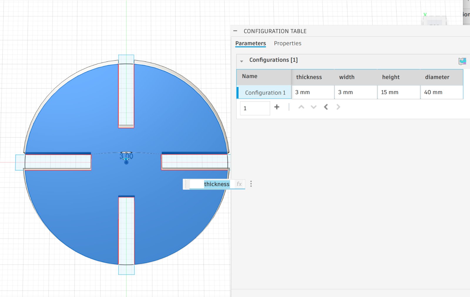
- Create a new user parameter: Click the “+” icon next to User Parameters. Enter the Name, Unit (mm, cm, degree, count), Expression/Value (number or formula), and an optional Comment. Press OK. Example: Name: height, Unit: mm, Expression: 3, Comment: “Cabinet height”. You can now utilize the ‘height’ parameter in sketch dimensions and features (extrusions, patterns, etc.). Any changes to its value will result in live updates to your model.
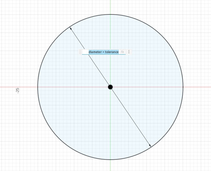
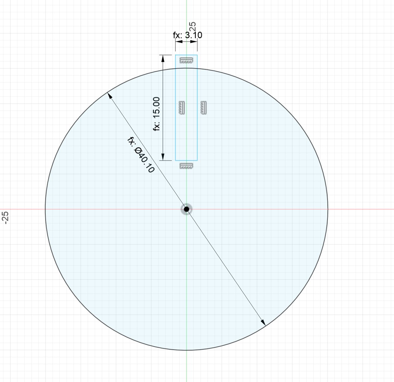
- Back to the sketch,the different is when you change the parameter value, the sketch will update automatically, you only need to fill in the name of the parameter, the value will be updated automatically.Here we can also add the tolorence value to the parameter, so that the model will be more accurate.
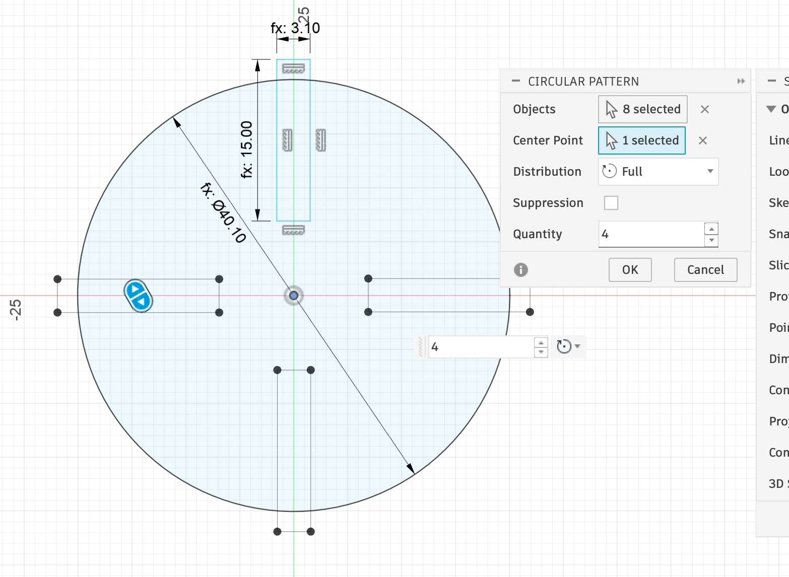
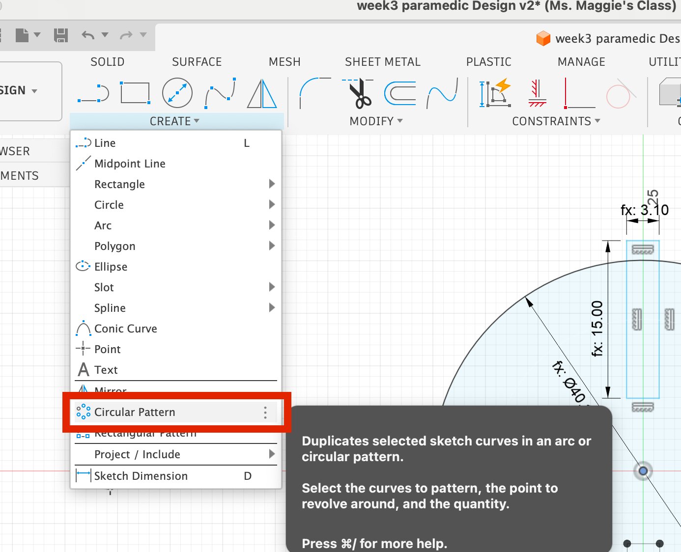
- Array the sketch to circular patterns.And then extrude the sketch.
- Export the model to STL file.
Kerf
We measured the kerf by cutting a rectangle 15 mm long and 3 mm wideter and measuring both the cut-out piece and the remaining hole with digital calipers. The difference, divided by two (one side each), gave a kerf of approximately 0.1 mm per side at the optimal cutting settings above. This value was used to offset paths in subsequent designs.
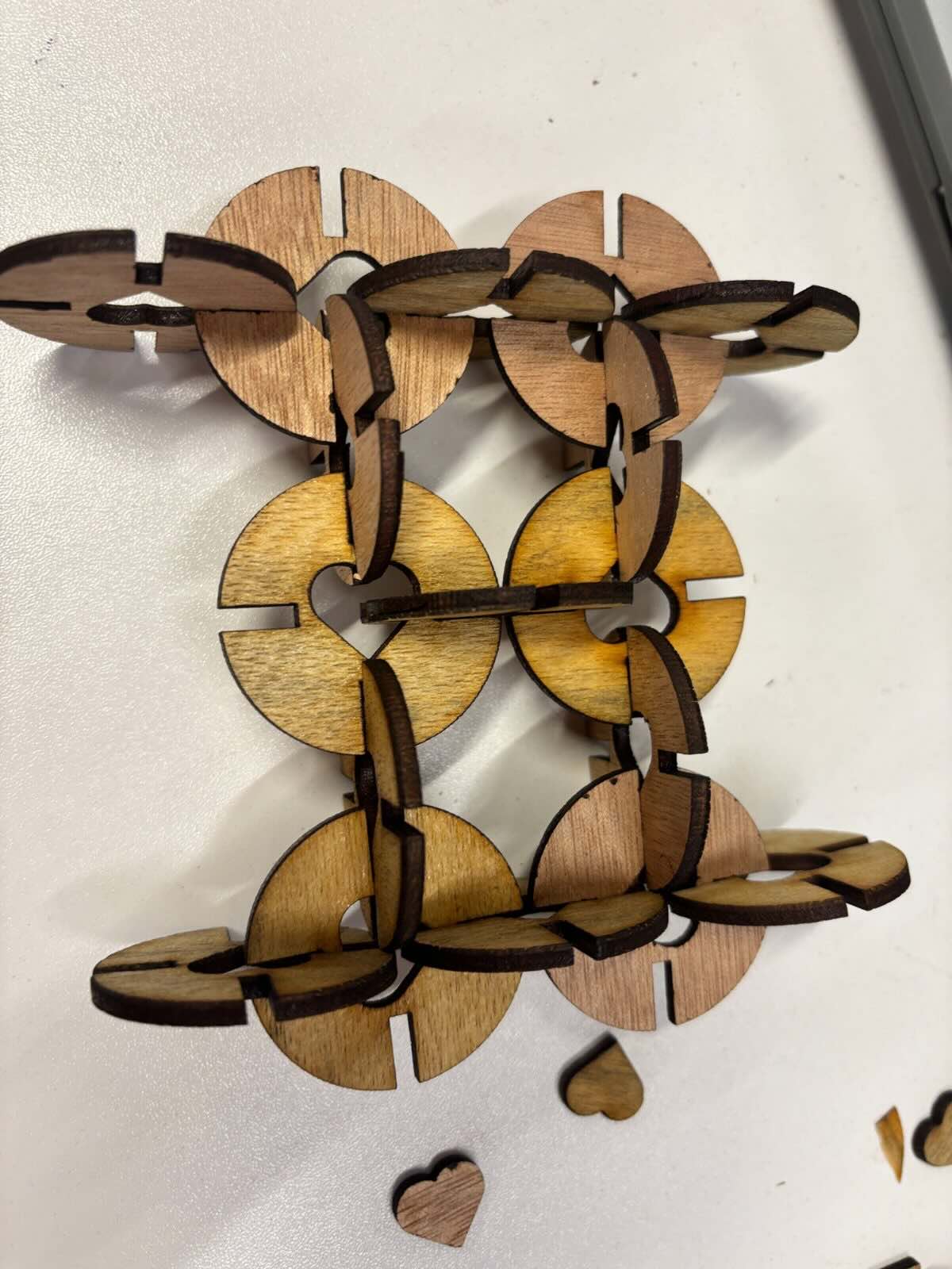
1.Laser Maker cutting & assemble practice
Designing a press-fit constrction kit using LaserMaker software.
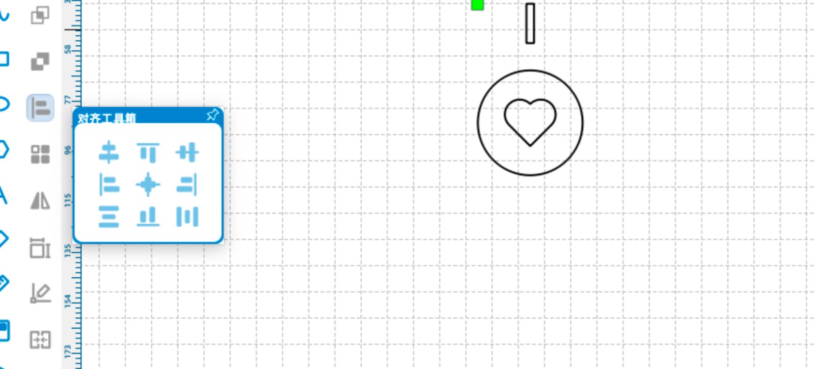
Open LaserMaker software and create a new project.Cleck circle button to draw a circle.Then choose a heart shape from the shape library and draw a heart shape. Use the alignment tool to align the centers of the two shapes.
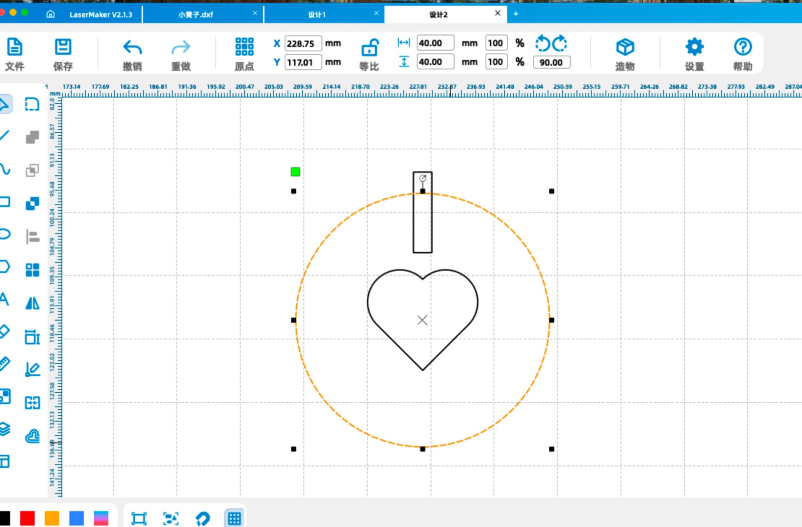
Select the circle to get the center point of the circle.Remember the X and Y coordinates of the center point.Then select the rectangle and use the circular array tool to make more rectangles.
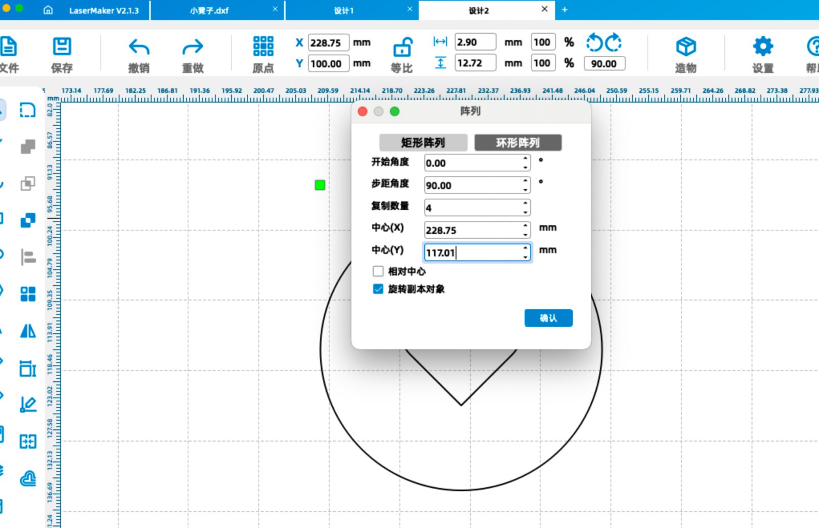
Remember to change the coordinates of the circular array to the center point of the circle, fill in the step angle 90 degrees and copy number 4, don't tick the Relative Centerize checkbox.Then the rectangles will be surrounded on the circle.
The center point of the circle is (228.75,117.01).So the center point of the circular array is (228.75,117.01).
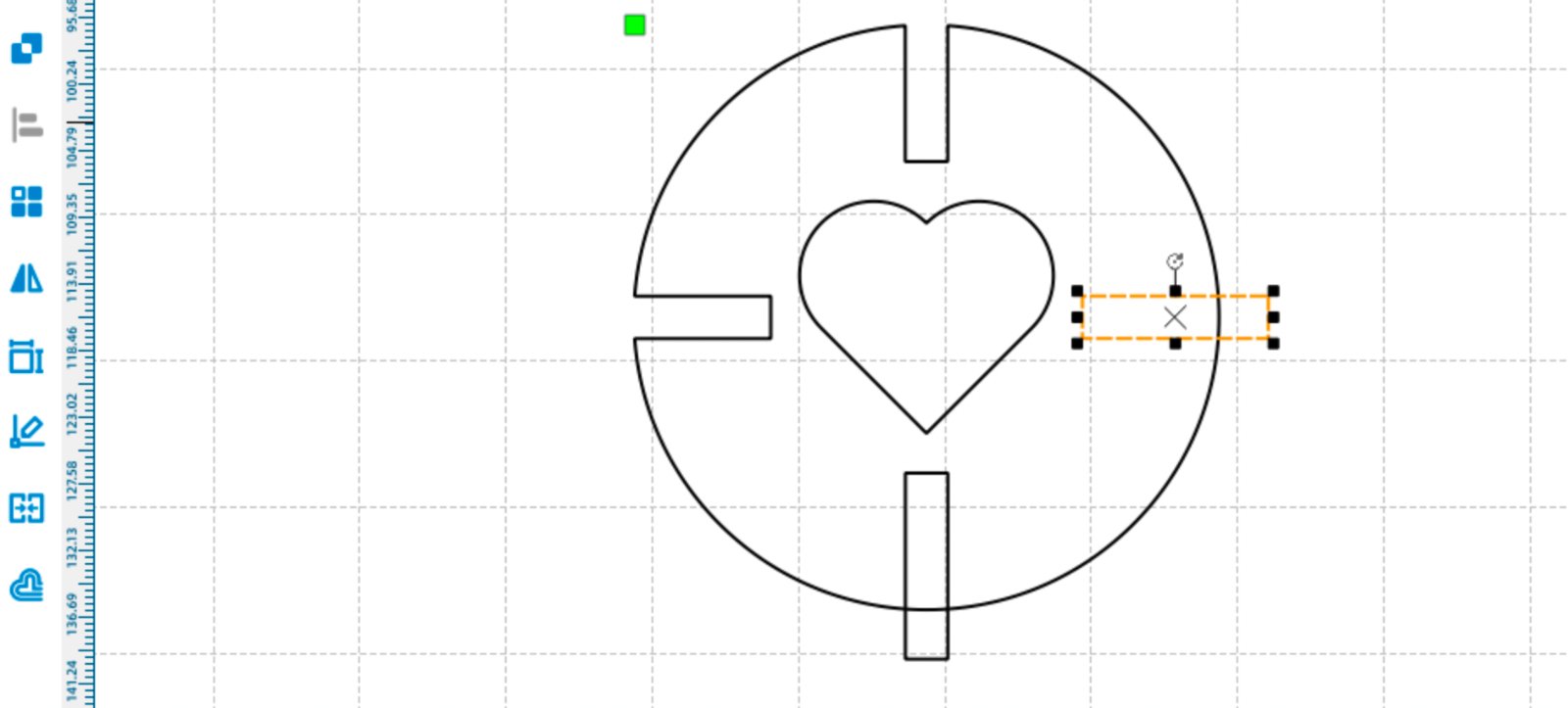
Select each rectangle and use the Difference Set Tool on the left side of tool bar to trim the outside part of the rectangle.
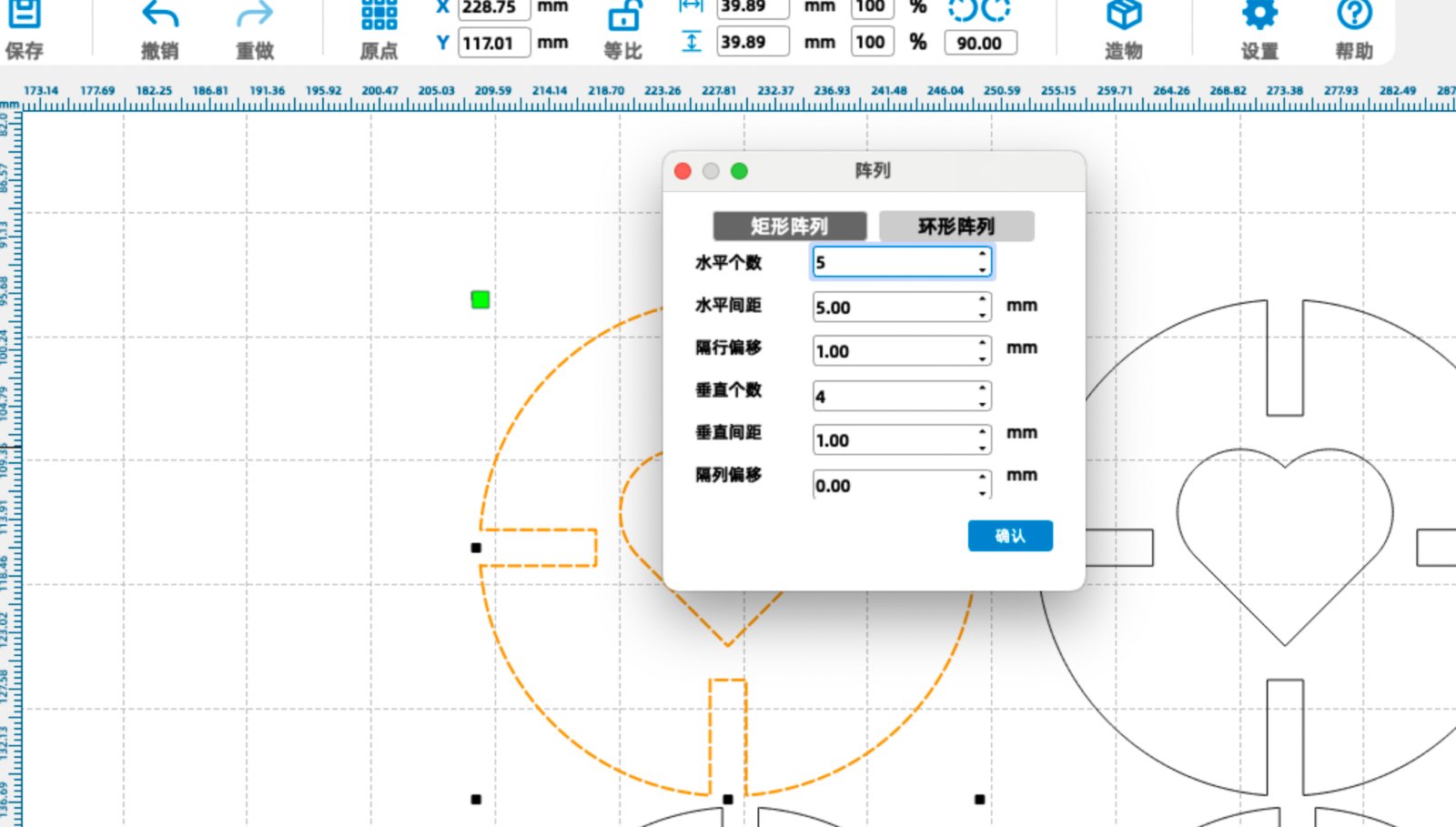
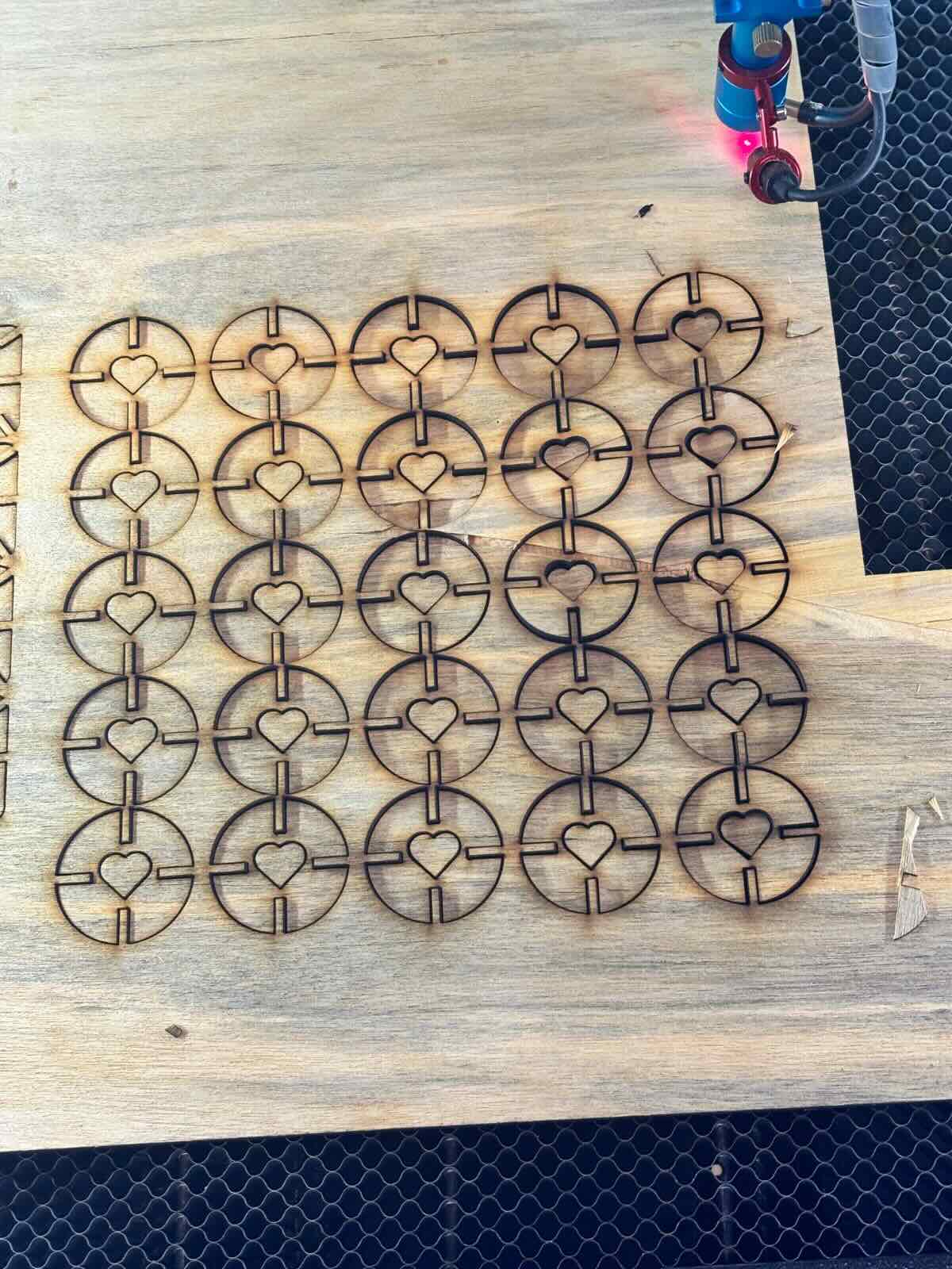
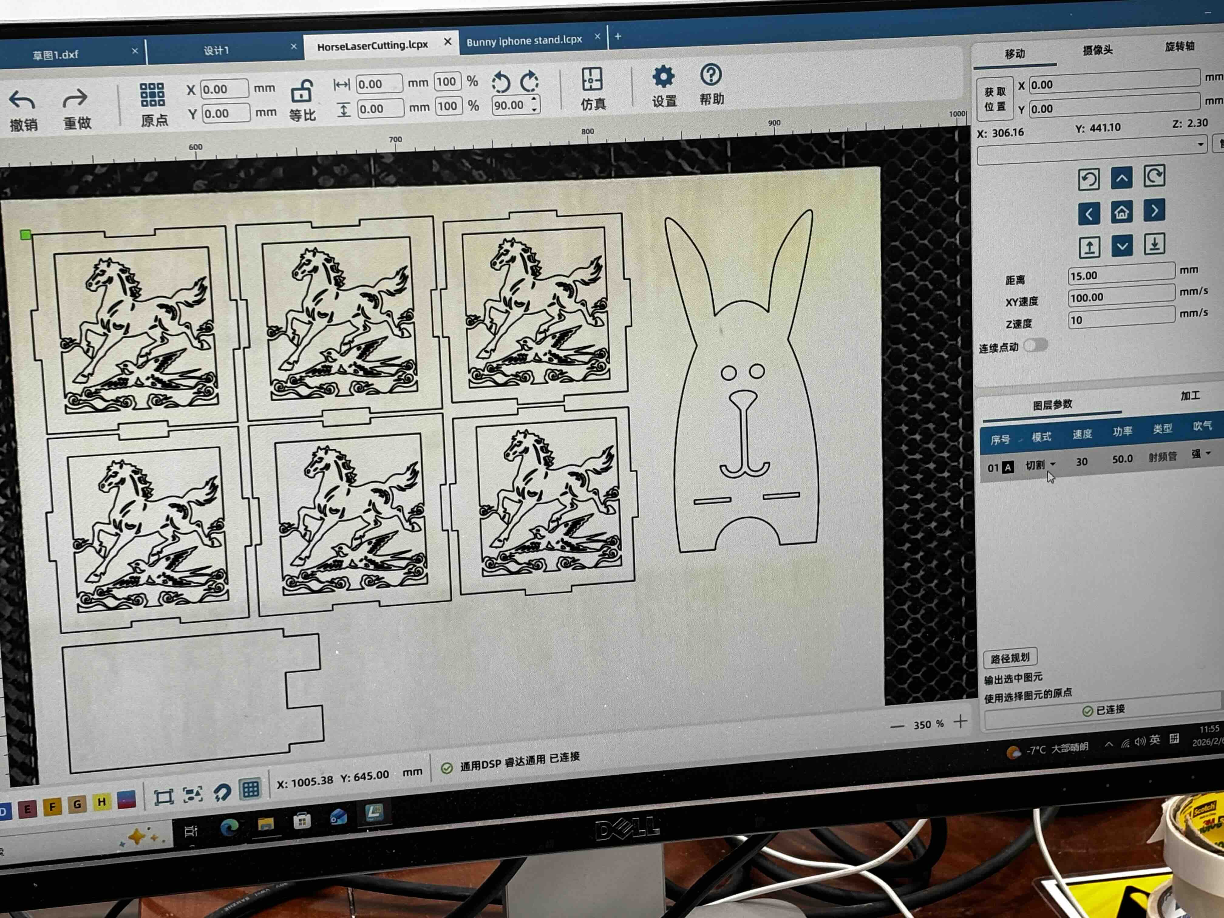
Select the whole shape and use the Grid Array Tool on the left side of tool bar to make the shape into a grid. Set up the horizontal count to 4, horizontal interval to 10mmand vertical interval to 40mm. Then you will get multiple shapes that looks the same. Download the .dxf format file and send it to the laser cutter.
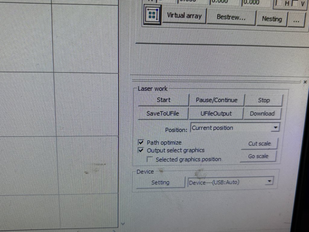
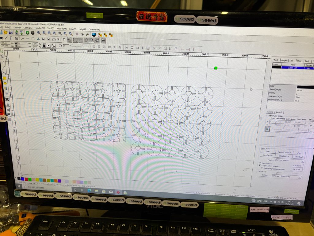
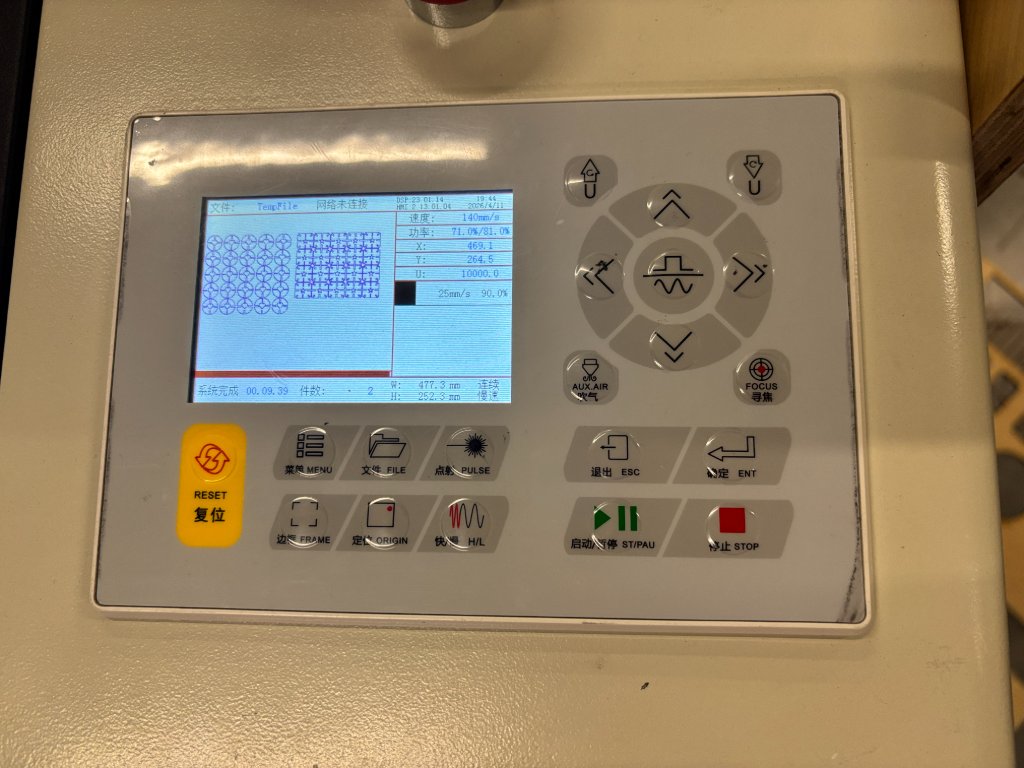
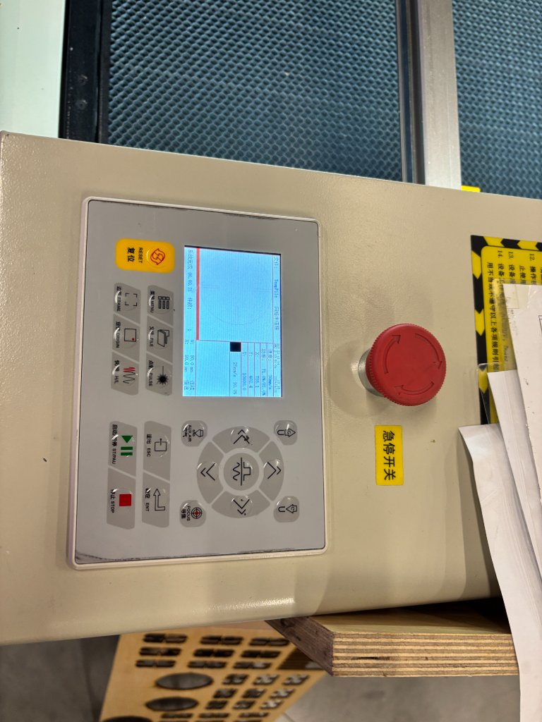
Set the speed to 30mm/s and Min Power to 70% max power to 90% then click Start Job button to start the laser cutting.
If an emergency arises suddenly, press the red emergency stop button.
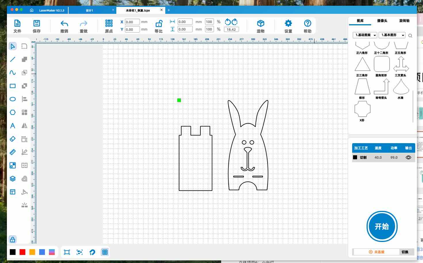
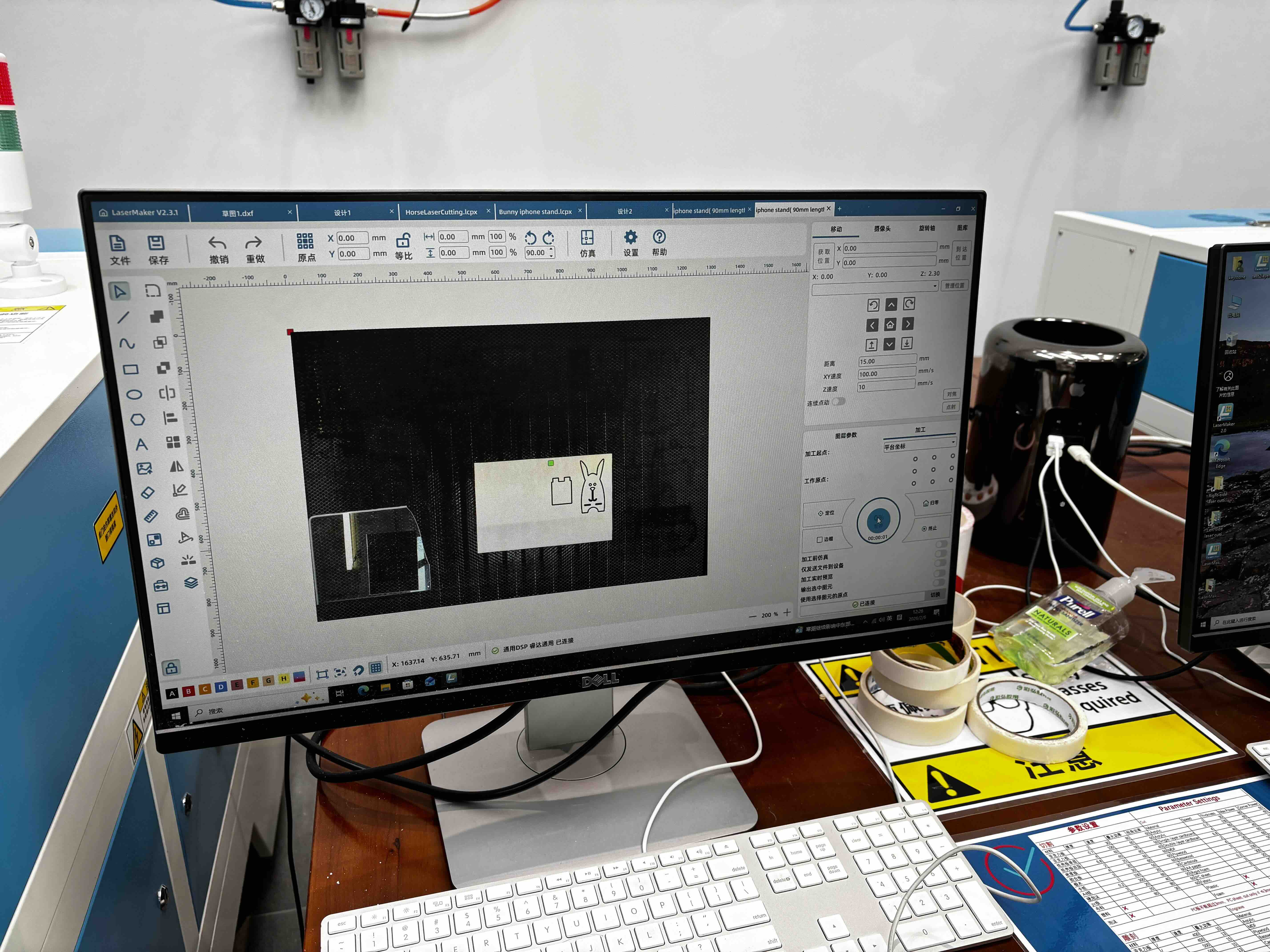
2.Laser Maker Software practice with phone stand
1.Search from the webset to see how to use the laser cutter to make a phone stand, and the idea about how to design the phone stand. 2.Designing the phone stand in LaserMaker software, and export the .icpx file.
3.Send the .icpx file to the laser cutter, adjust the parameters and material of the laser cutting, and wait for the laser cutting to complete.
4.After lasering, the press-fit constrciton is not designed well, so it's hard to assemble them together, I think the reason is becasuse the tolorance of the width of the socket and the thickness of the wooden board is not accurately matched, so I am using the vernier caliper to measure the width of the socket and the thickness of the wooden board and record the data.Then I adjust the parameters of the laser cutting to make the press-fit constrciton more accurate.
2D Vinyl Cutter Practice
For the individual assignment extension, I used the lab 2D vinyl cutter to cut the Spark Week logo. The workflow below follows the lab vinyl plotter guide (AIDCut-CAM software).
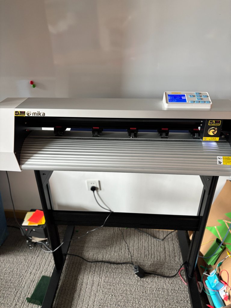
Vinyl plotter operation guide (AIDCut-CAM)
Step 1 — Open AIDCut-CAM
Launch the AIDCut-CAM software on the computer connected to the vinyl cutter.
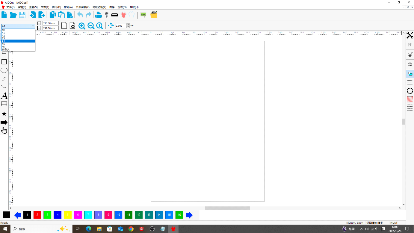
Step 2 — Select paper size
Choose the sheet size that matches the media loaded on the machine.
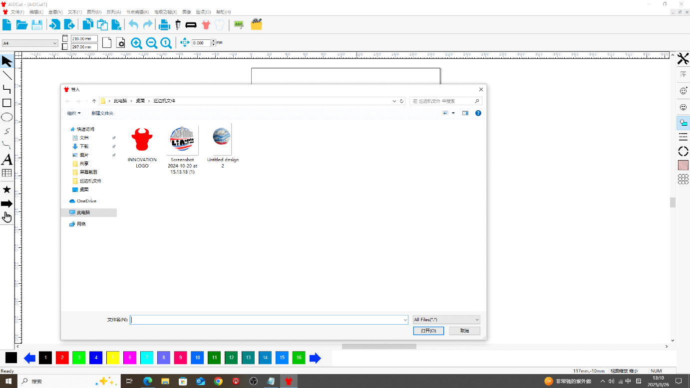
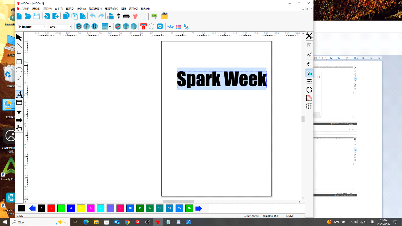
Step 3 — Import artwork or add text
After confirming the page size, import your image file, or click the Text tool on the toolbar to type text directly.
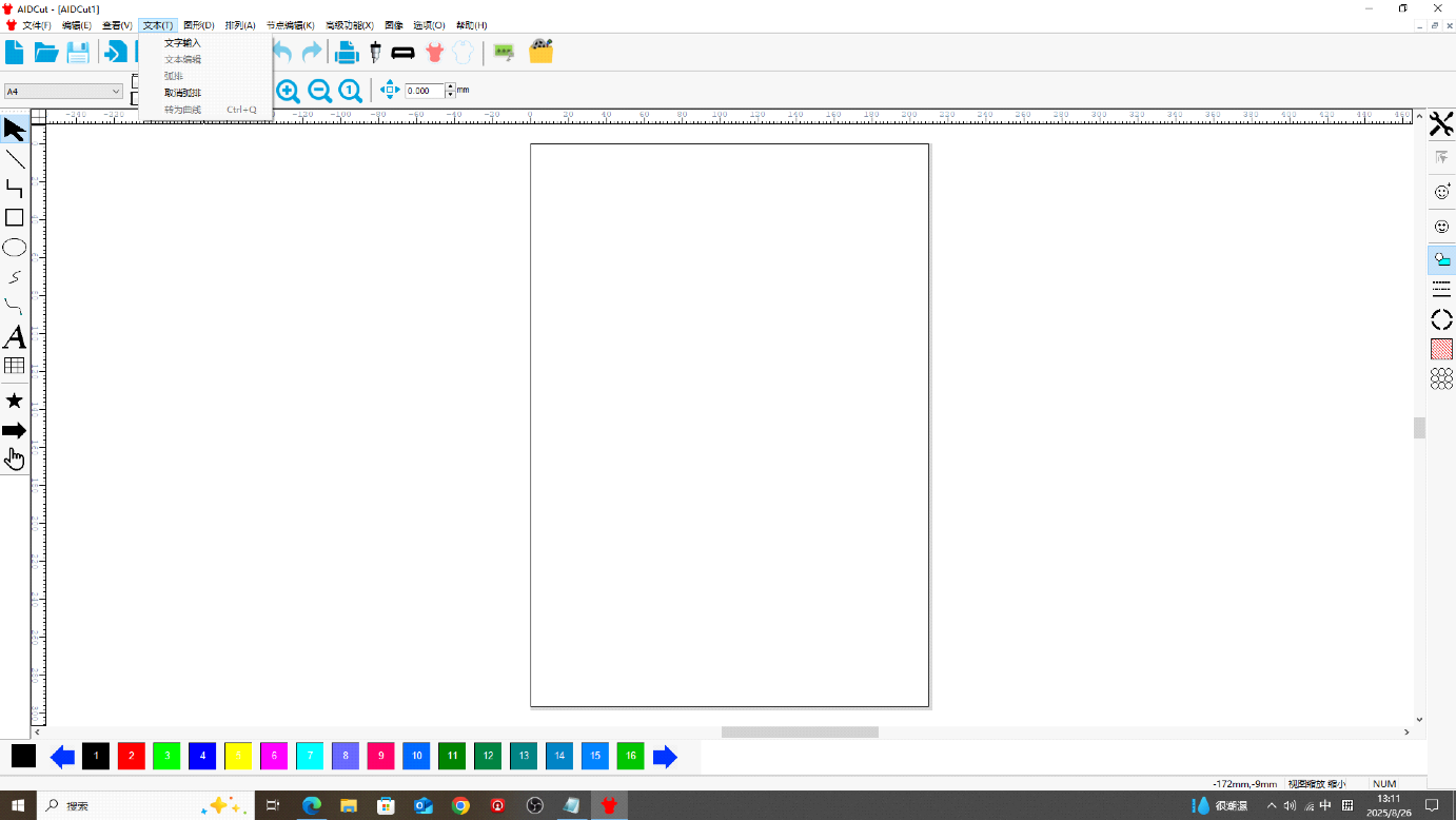
Step 4 — Set font and size
Select the text, then choose font and font size from the options at the top left.
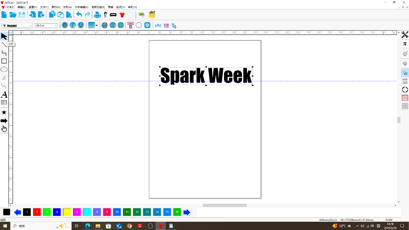
Step 4 (continued) — Move and scale
Click the Arrow / Select tool on the left toolbar, select the text, then drag to reposition or scale the whole object.
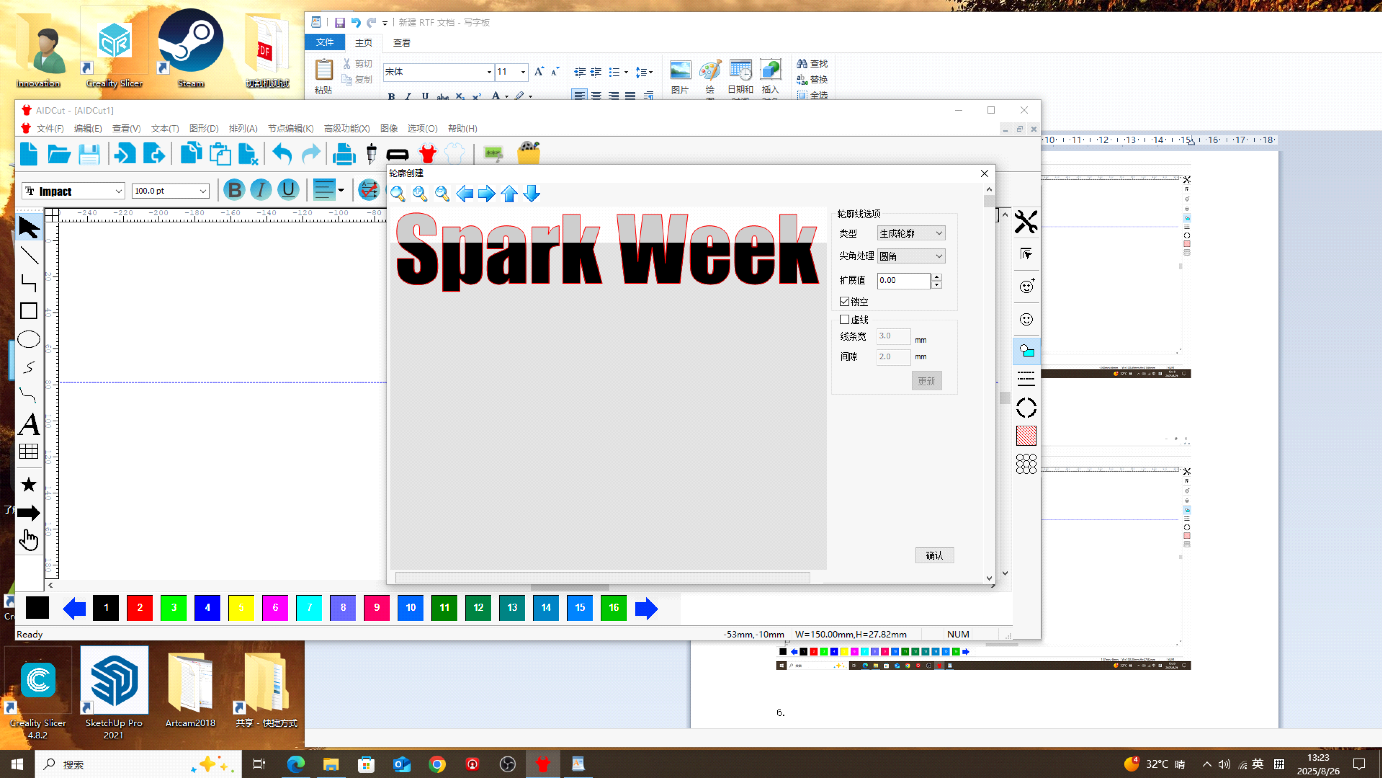
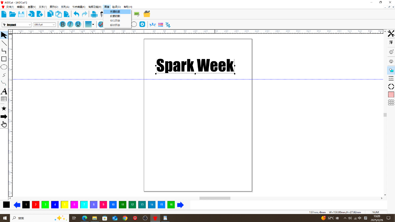
Step 5 — Create cutting outline
In the top toolbar, open the Image menu, choose Create Outline, then click Confirm.
Step 7 — Set origin on the machine
Before plotting, calibrate the start position on the cutter. Click Online / Pause until the machine shows offline status, then adjust the X and Y axes to set the origin point.
Step 8 — Set speed and pressure
Click Online / Pause again, then set the plotter speed and pressure (blade force).
- Plain white paper: speed 66–68 mm/s, pressure 160 g; thick cardstock ~185 g
- Adhesive vinyl (sticker paper): speed 68 mm/s, pressure 216 g
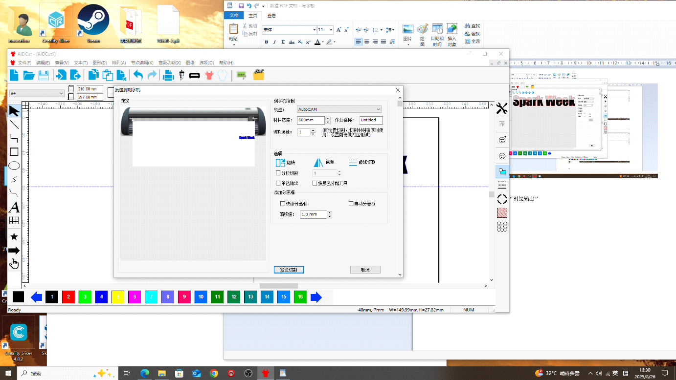
Step 9 — Send cut job
In the top toolbar, choose Plot Output, send the job to the cutter, and confirm plot output.
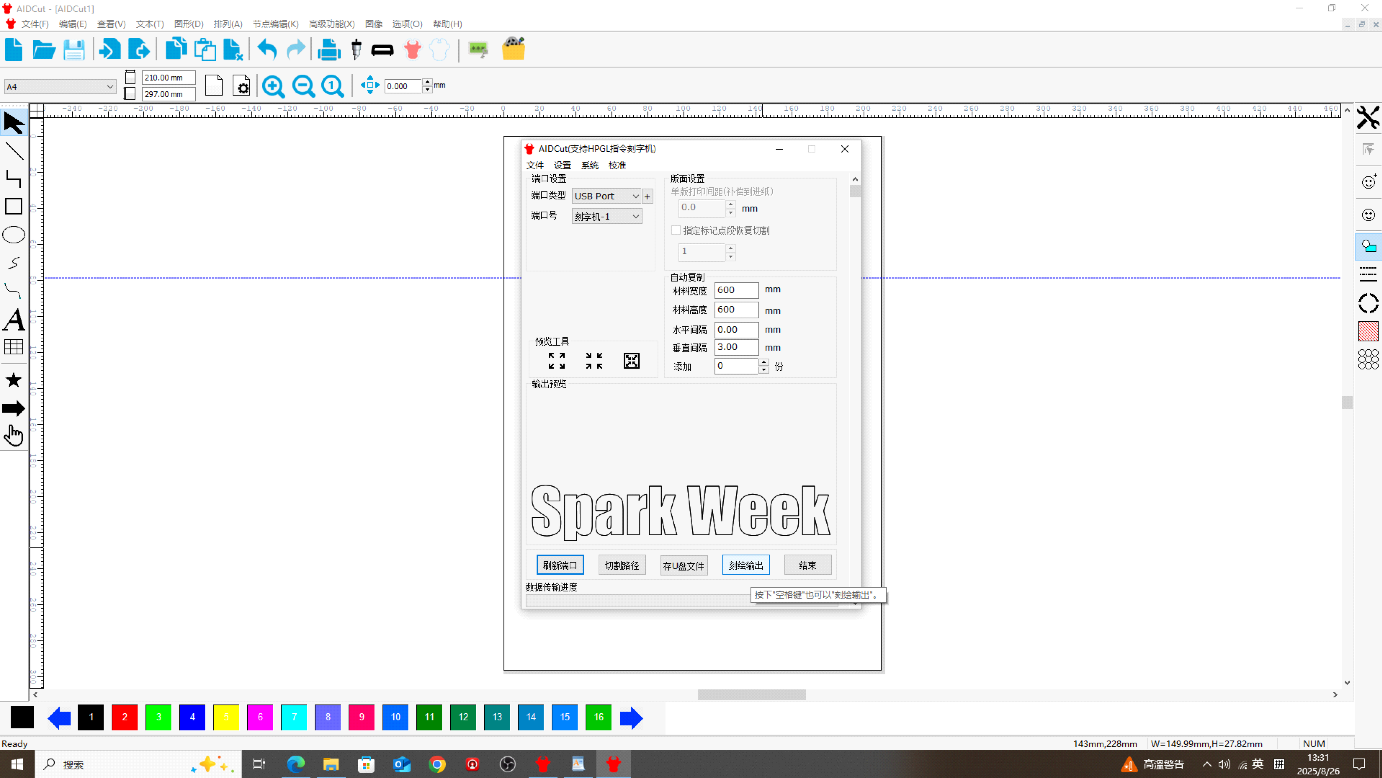
My result: Spark Week logo cut on adhesive vinyl using the settings above.
Vinyl Cutter Demo Video
Resource Files
- Lasermaker
- Find the perfect Fit Tolerance for Laser Cutting
- Lasermaker assemble practice.dxf — source file (DXF)
- Bunny iPhone stand.icpx — source file (icpx)
- week3_parametric design.stl — source file (STL)