Week 2: Computer-aided Design
This week I worked on comparing Onshape, Fusion and Rhino first and at last I choose to learn Fusion as a CAD software tools for my final project.
Image and Video Files Compression
For web documentation, keeping file sizes small is essential for fast page loading and staying within GitLab repository limits. Below are the workflows I used to compress images and videos.
Image Compression
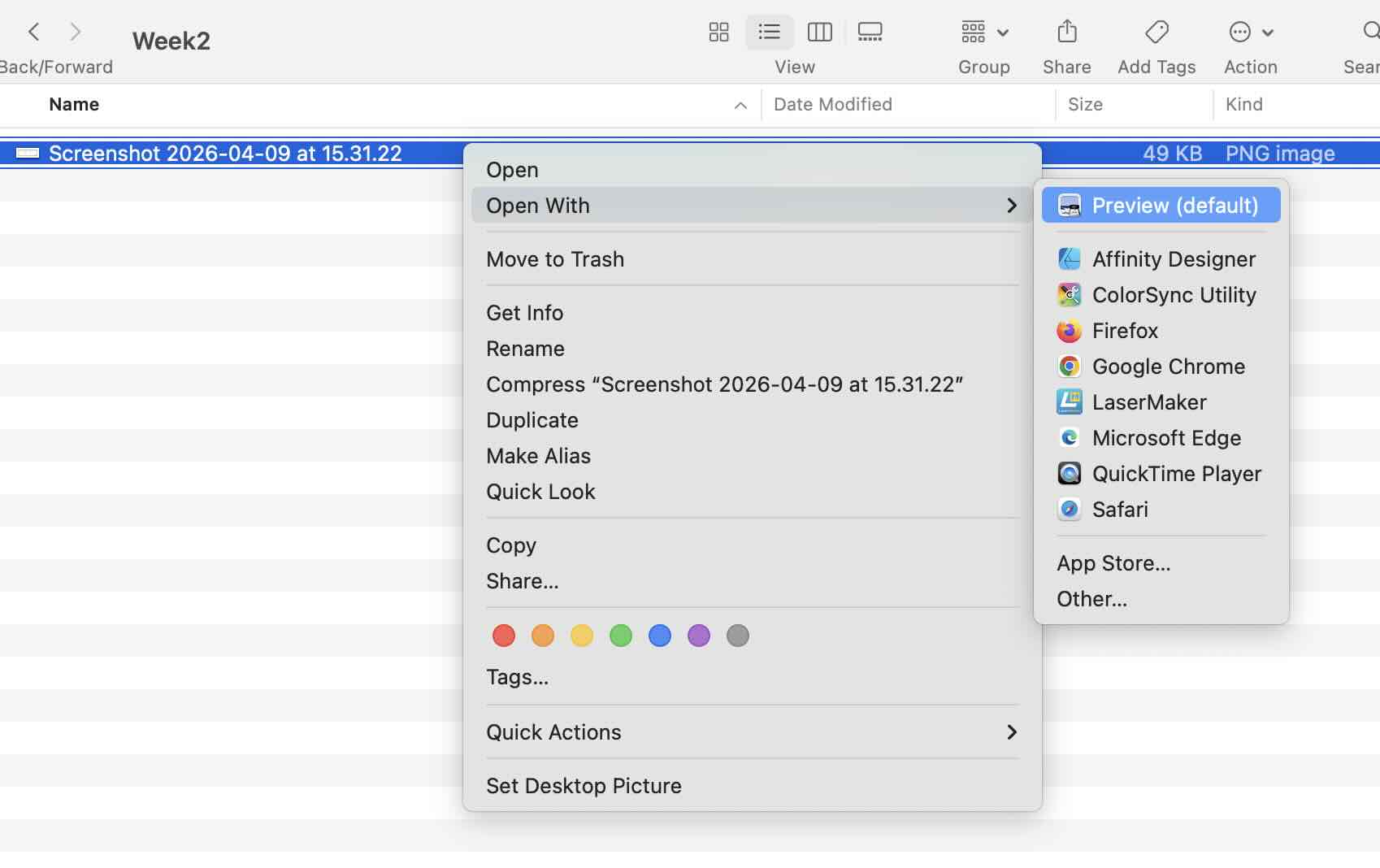
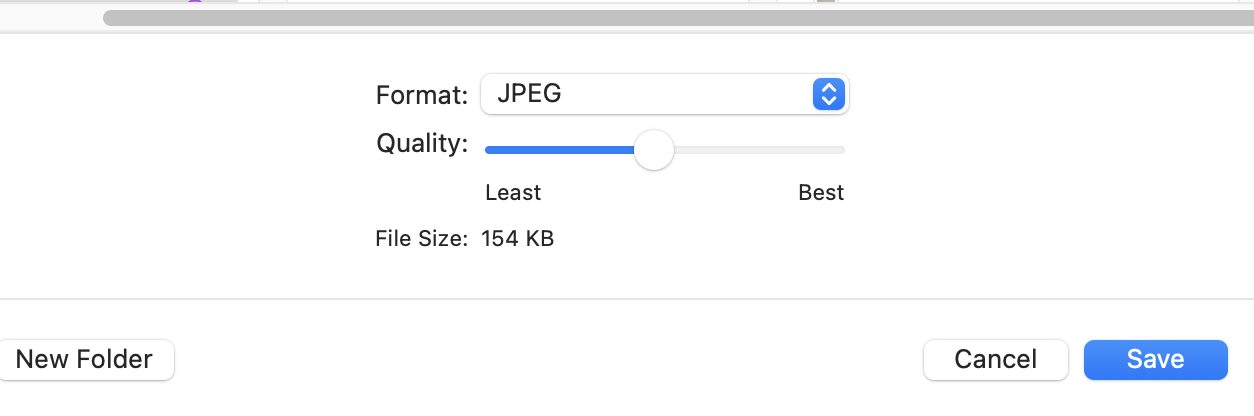
1.I used Mac default preview tool to compress the images. When opening the photo,under the file menu, there is a option called "export",and you can change the quality and format of the image. But the downside is that it can only compress one image at a time, and very large images cannot be compressed to a significantly smaller size.
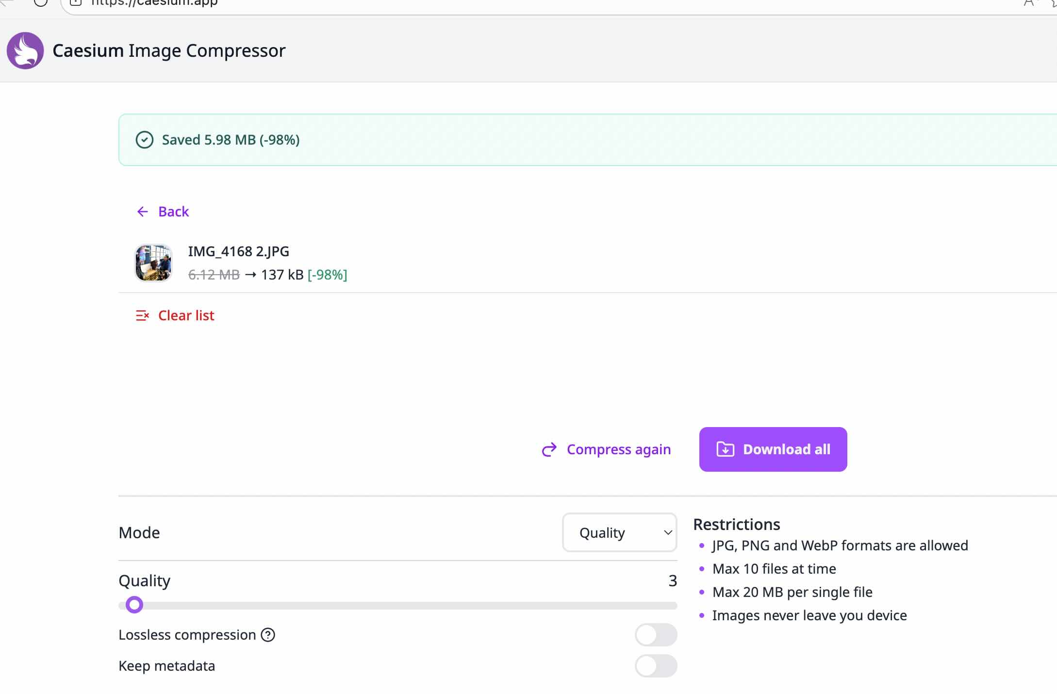
2.I used the online tool called "Caesium Image Compressor" to compress the images. It is a free online tool that can compress images to a significantly smaller size. It is a very easy to use tool, you just need to upload the image and click the "compress" button, and then download the compressed image.
Caesium Image Compressor is a free, open-source image optimization tool developed by Matteo Paonessa. It supports Windows, macOS, and Linux platforms, offering both GUI and command-line versions. The software enables users to reduce image file sizes by up to 90% without significant visual quality loss. It supports major formats including JPEG, PNG, WebP, TIFF, BMP, and GIF. Key features include batch processing, real-time before/after preview, customizable compression quality, metadata management, and folder structure preservation.
Video Compression
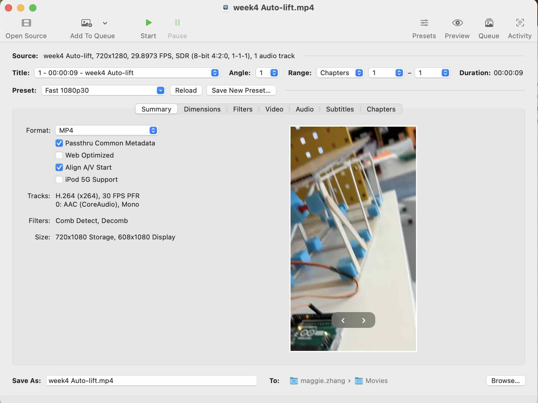
I used HandBrake APP to compress the videos. It is free, open-source, and available on Windows, Mac, and Linux. It can significantly reduce video file sizes while maintaining good visual quality.
Fusion 360 Design.
1.I download Fusion 360 and install it on my computer.
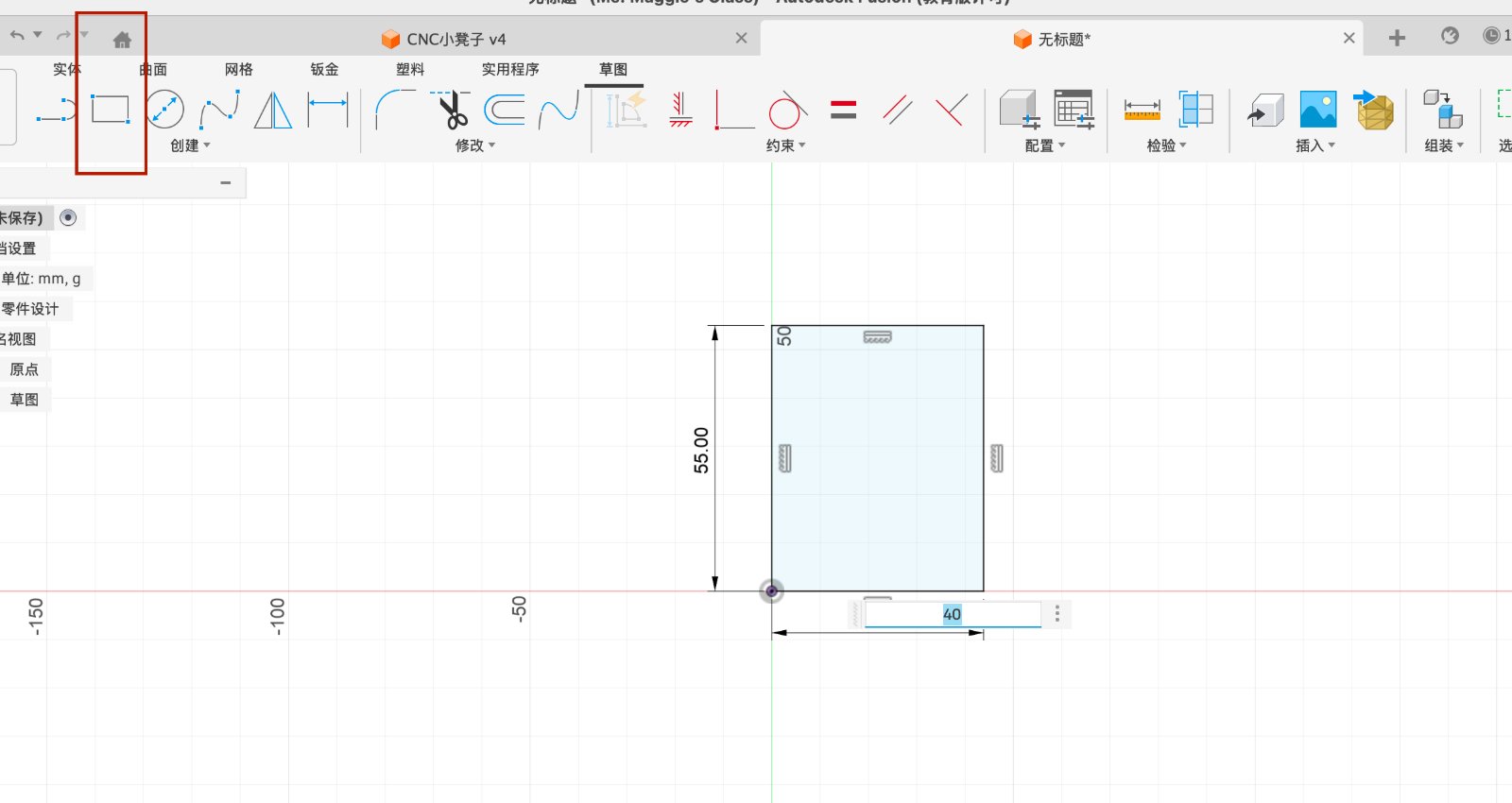
2.Create a New Design & Sketch the Profile
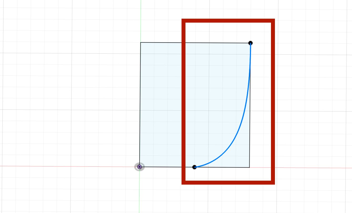
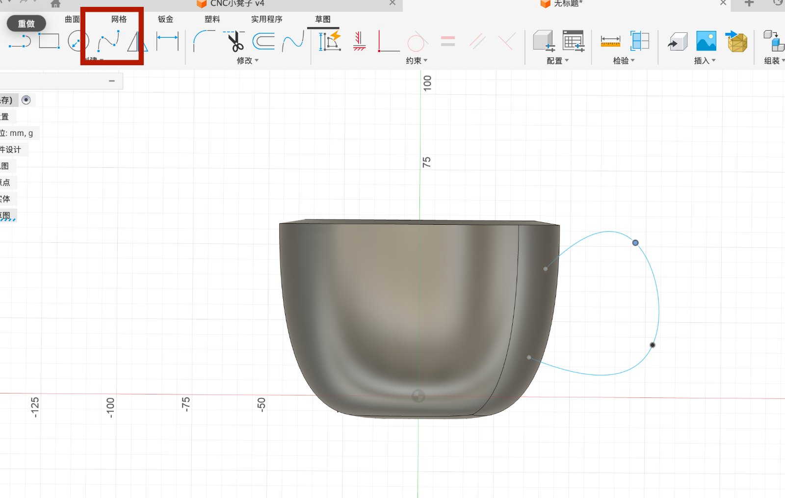
Launch Fusion 360 and click on the File menu, then select New Design to start a fresh project. Click Create Sketch and choose the XZ Plane (the vertical plane) as my workspace. Draw a rectangle with the following dimensions: Height: 55 mm Top Width: 40 mm
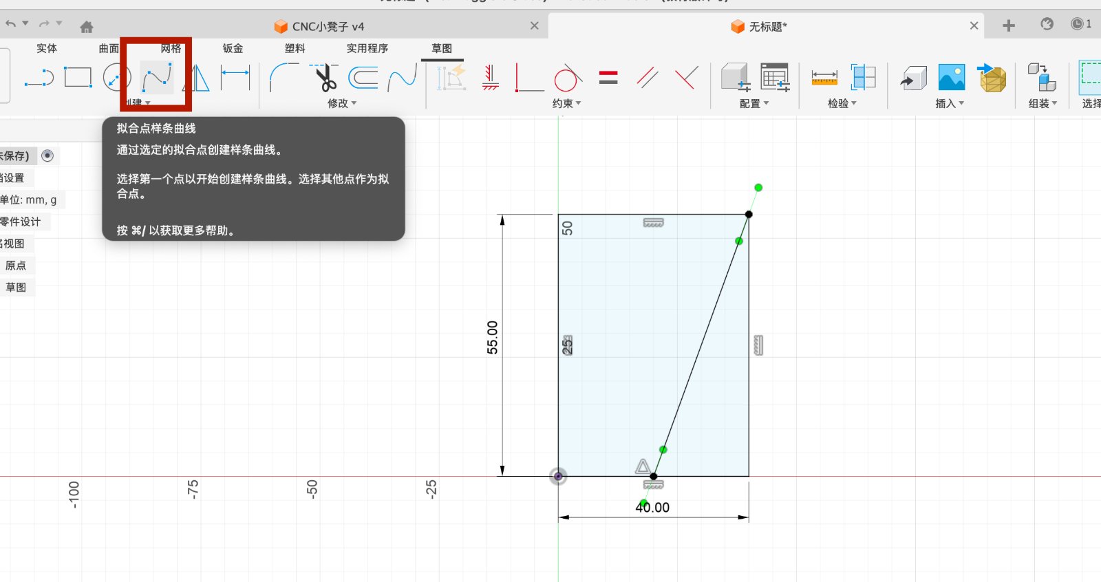
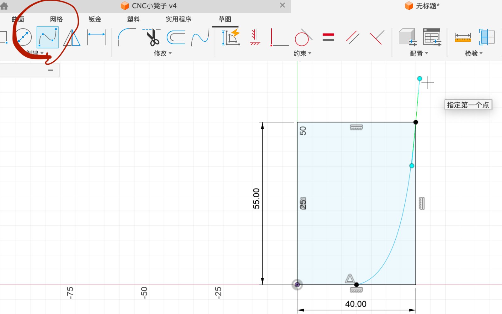
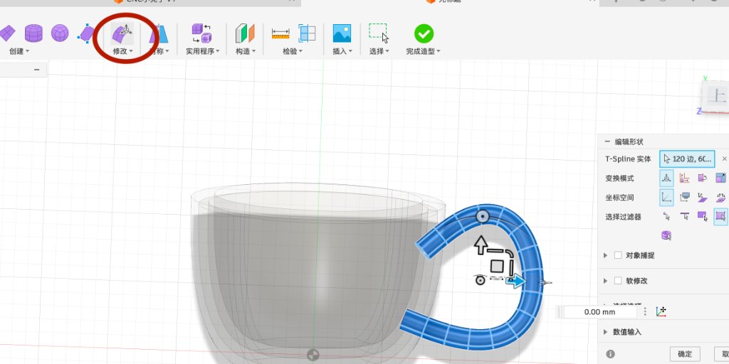
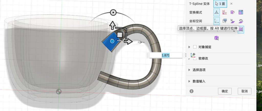
Using the Fit Point Spline to draw the curve.
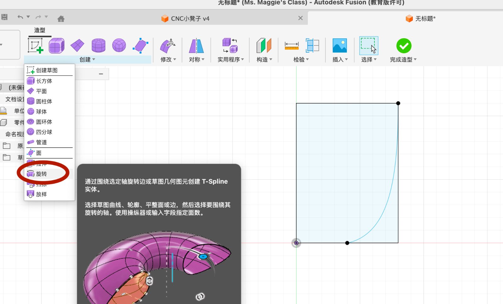
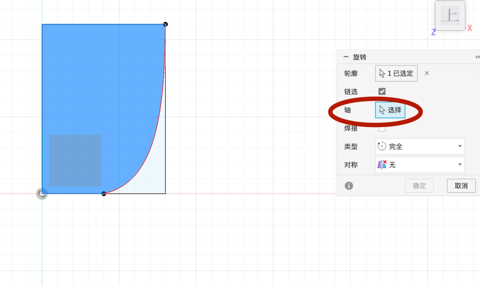
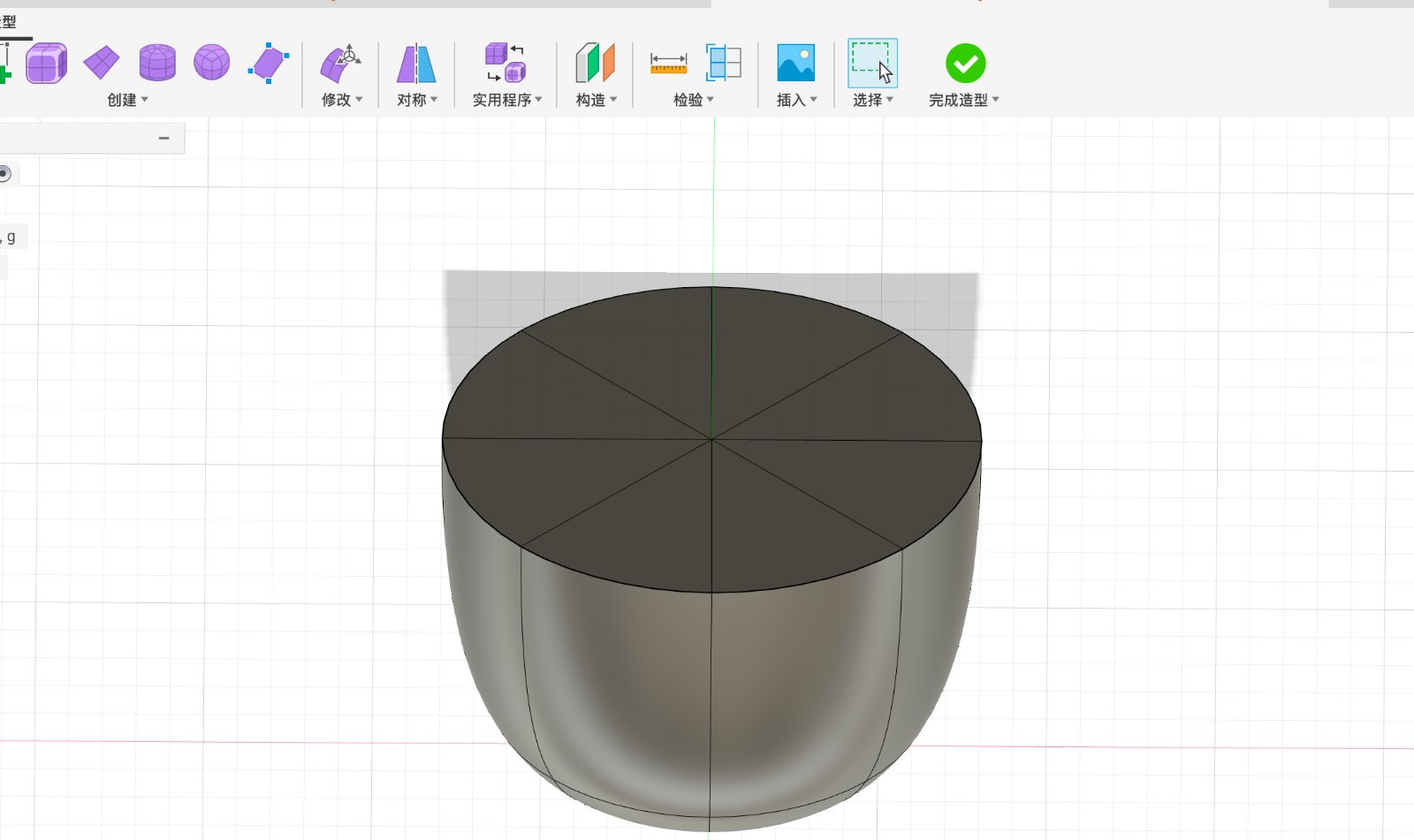
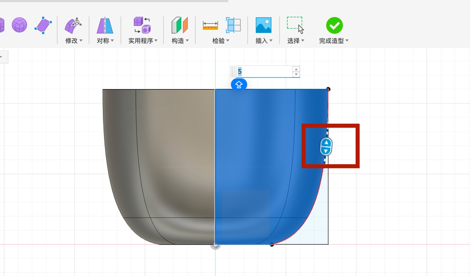
3.Use the Revolve Feature
Go to Solid tab and cleck revolve button after selecting the curve sketch, then for the Axis, pick the vertical center line of the sketch.And set the Angle to 360 degrees. The key point of this step is that select the curve sketch first, then select the revolve button, and then select the axis instead of the whole sketch.
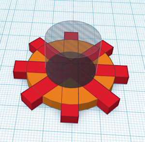
Make a gear in Tinkercad
Tinkercad is a free online tool for creating 3D models. It is a very easy to use tool, you just need to drag and drop the shapes to create your model. You can also use the code to create your model. Also it's a free app not only for 3D design, but also for electronics and coding.
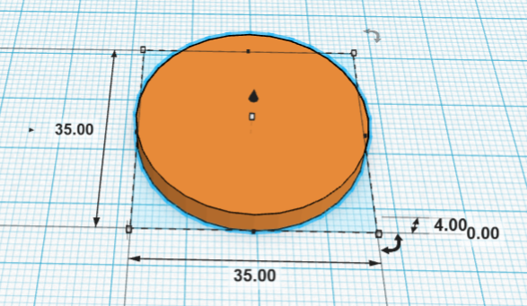
First, add the cilender to the mian part of the gear, by drag and drop the cilendar to the workplane.Then change the cilendar's dimensions to 35mm in length and 35mm in width, 4mm in height./p>
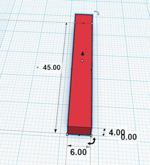
Adding and resize the box to the workplane, by drag and drop the box to the workplane.Then change the box's dimensions to 45mm in length and 6mm in width, 4mm in height.
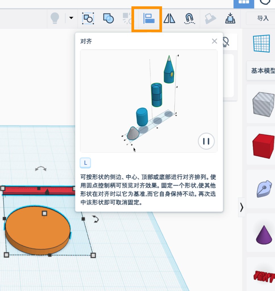
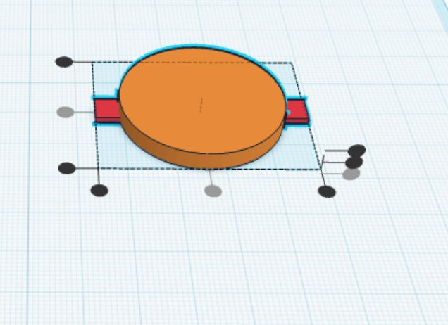
Moving the box into the center of the cilendar, by select the align button on the toolbar,click the two middle dots to the center of the cilendar.
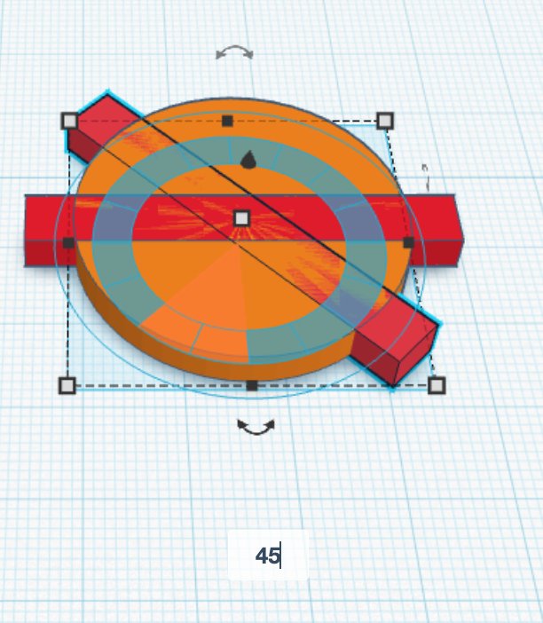
Select the aligned box,using curve arrow to rotate the box to 45 degrees.
Add a hole to the center of the gear, by select the hole celender and aligned.
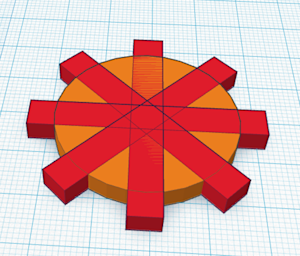
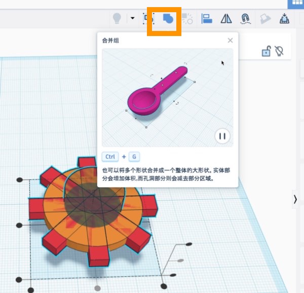
Group them together, by select the group button on the toolbar to combine the shapres in a gear.
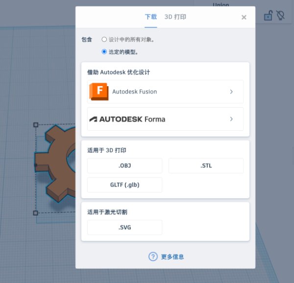
Export the gear to STL file, by select the file menu, then select export, then select STL file, then confirm. The STL file will be exported to the desktop.
Source file
Make a gear in Tinkercad — Tinkercad gear design (Tinkercad export).
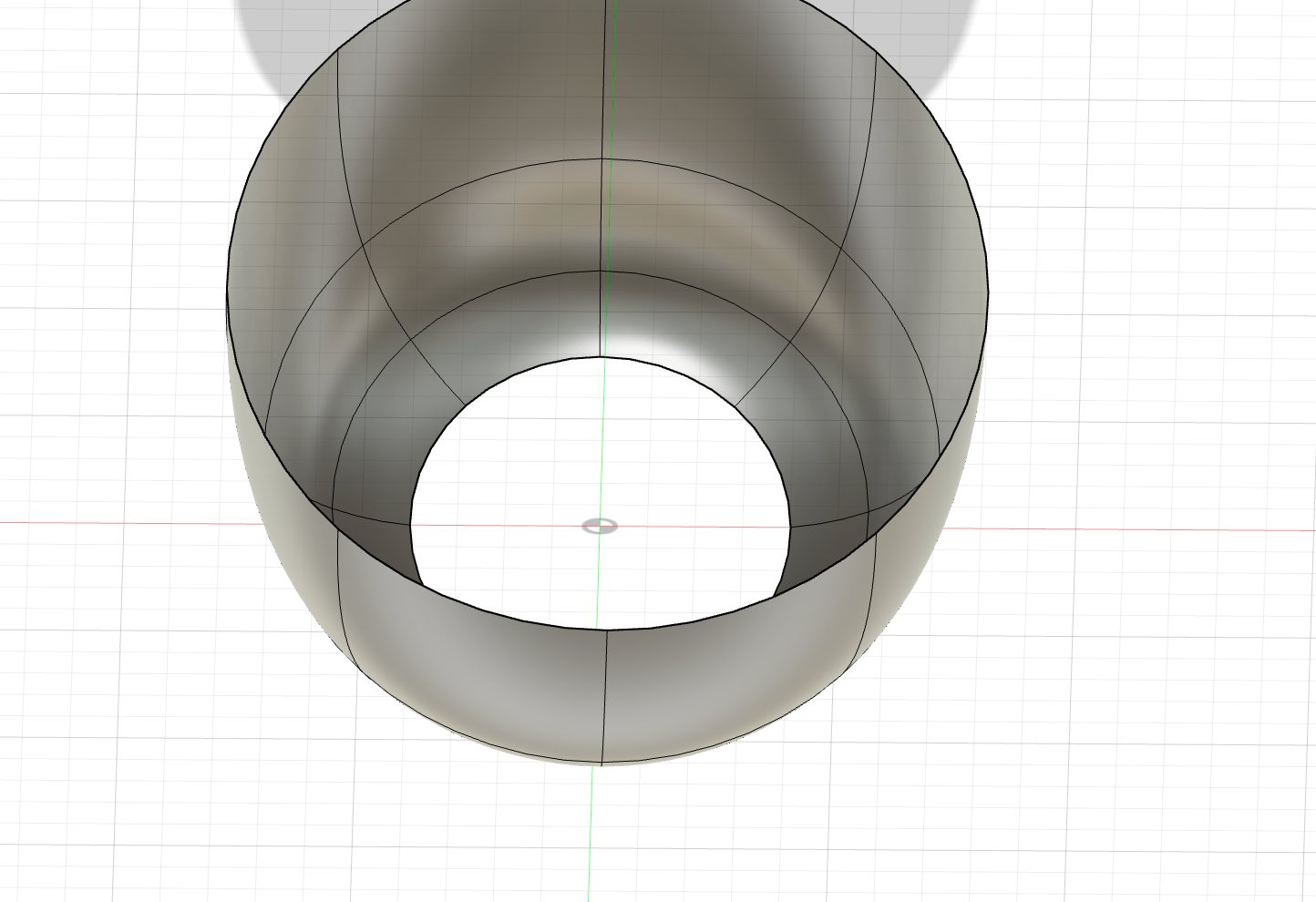
Source file
cup.stl — Fusion cup design (STL export).
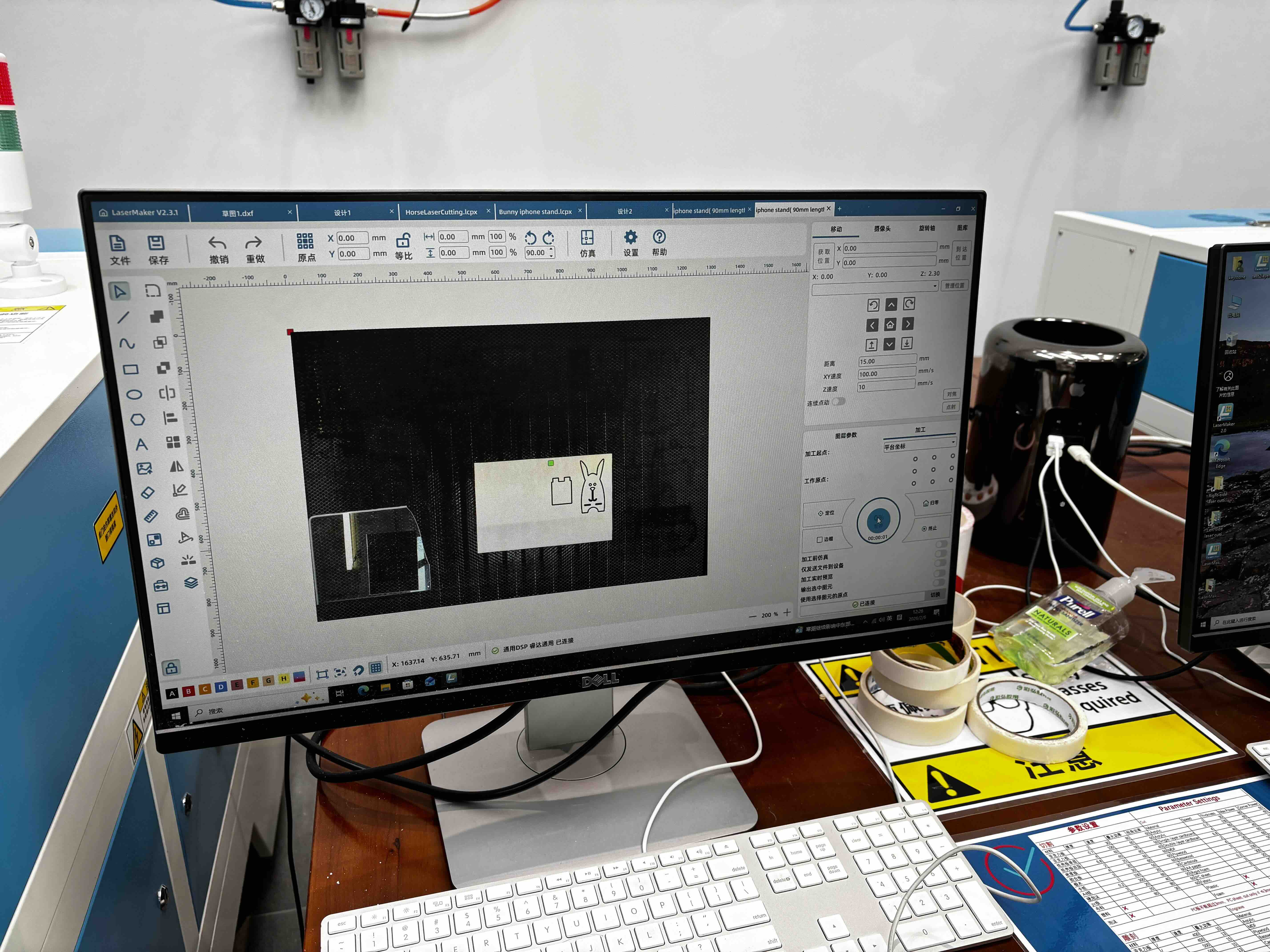
2D Design with LaserMaker
LaserMaker is the 2D design software paired with Thunder Laser cutters. For Week 2 I used it to design a press-fit construction kit. Below is the step-by-step design process in LaserMaker.
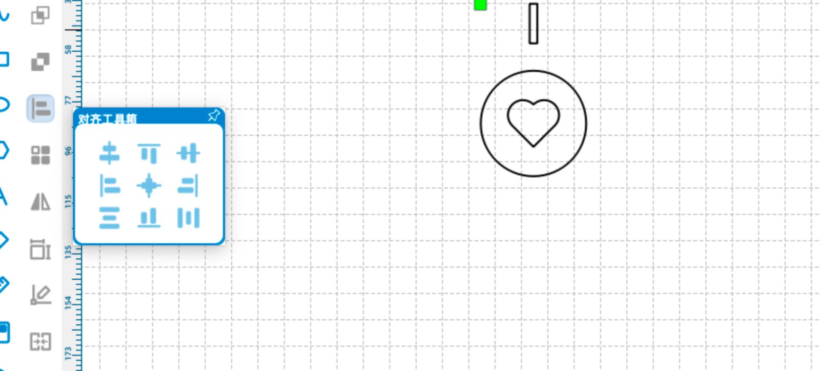
1. Create a new project and draw basic shapes
Open LaserMaker and create a new project. Click the circle tool to draw a circle, then pick a heart shape from the shape library. Use the alignment tool to align the centers of both shapes.
2. Circular array around the center point
Select the circle to read its center coordinates (X, Y). Select the rectangle and use the Circular Array tool: set the array center to the circle center, step angle 90°, copy number 4, and do not tick Relative Centerize. Four rectangles will surround the circle.
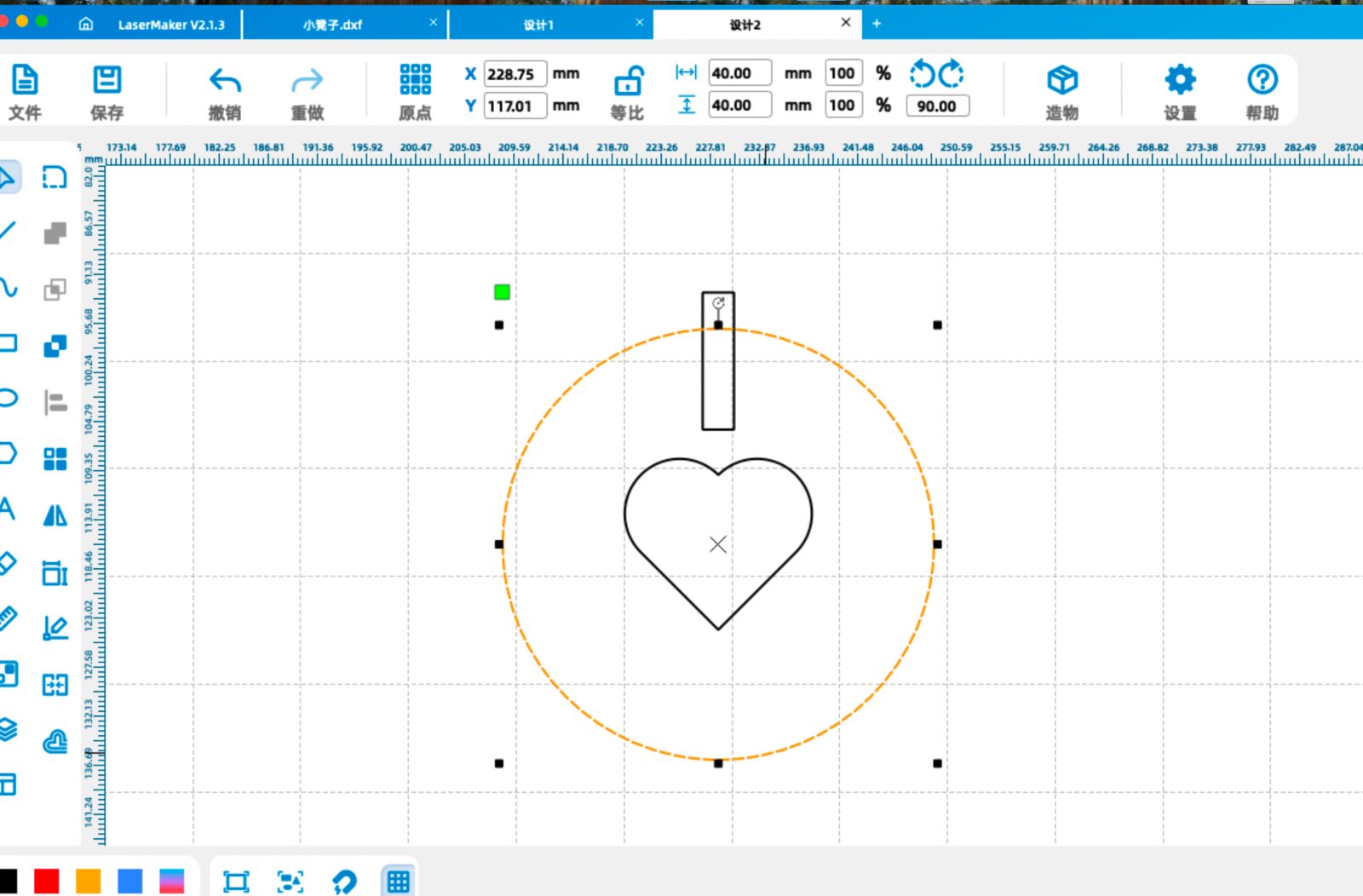
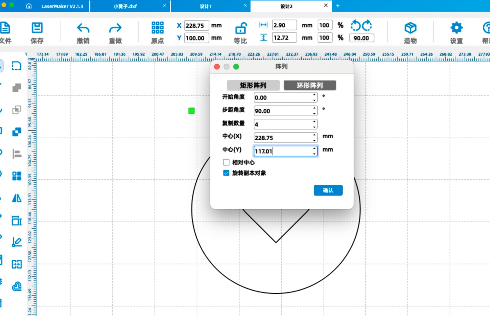
Example center point: (228.75, 117.01).
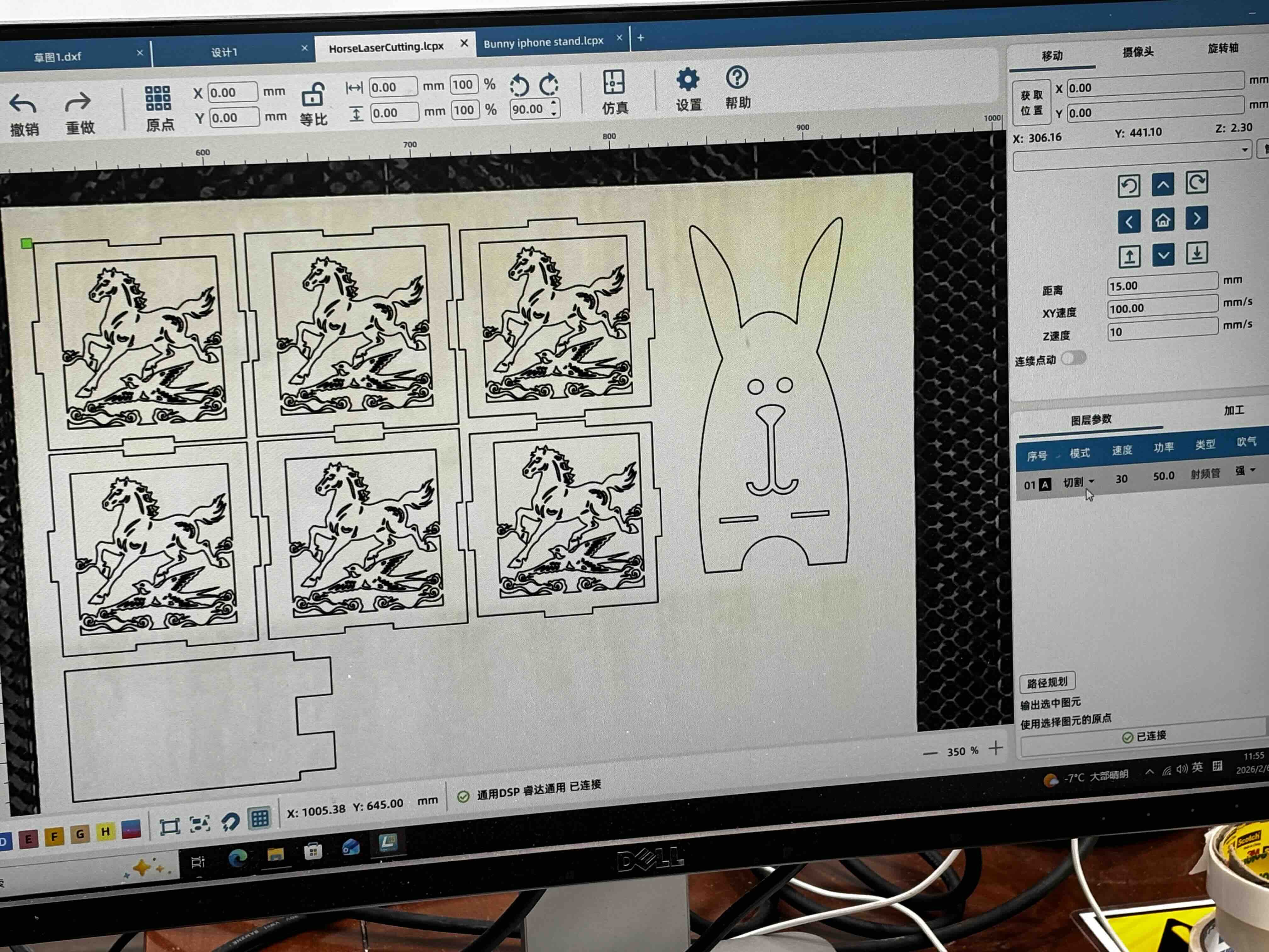
3. Difference set and grid array
Select each rectangle and use the Difference Set tool on the left toolbar to trim the outside of each rectangle against the circle.
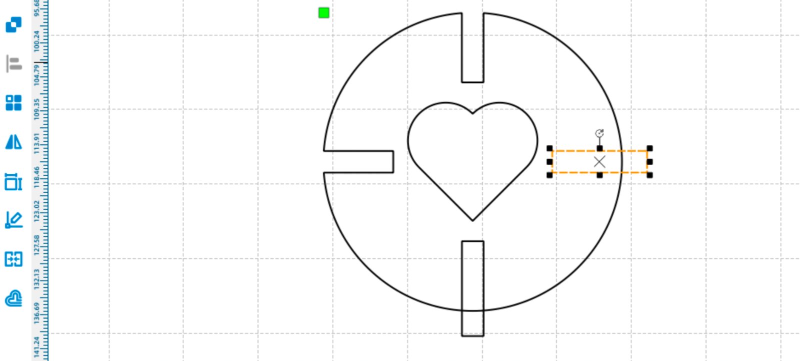
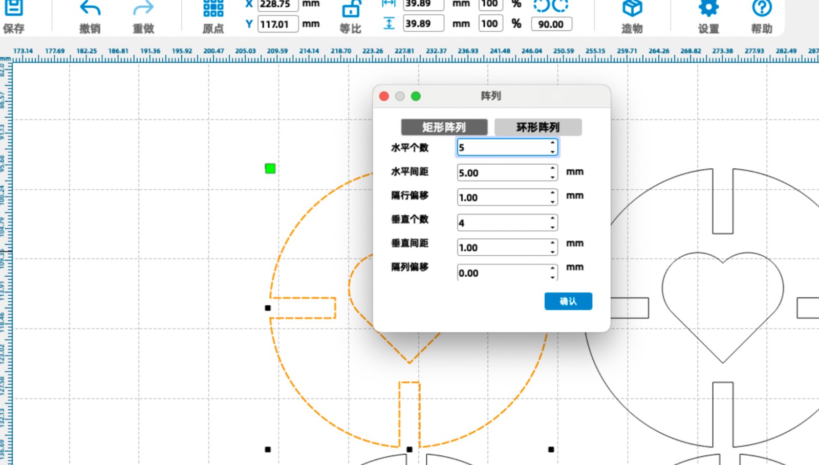
Select the whole shape and use the Grid Array tool: horizontal count 4, horizontal interval 10 mm, vertical interval 40 mm. Export as .dxf for laser cutting.
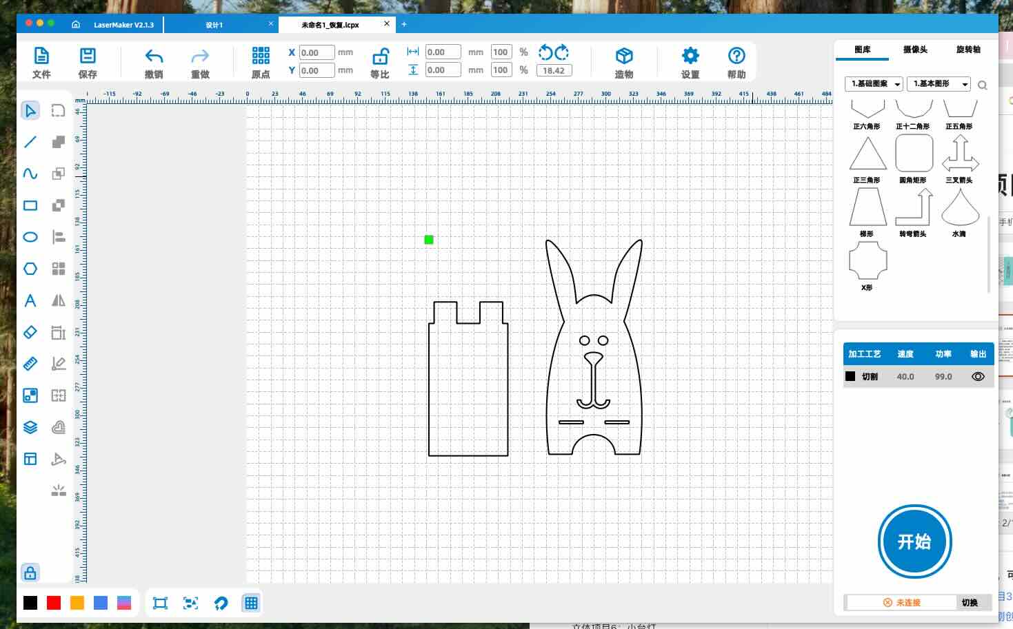
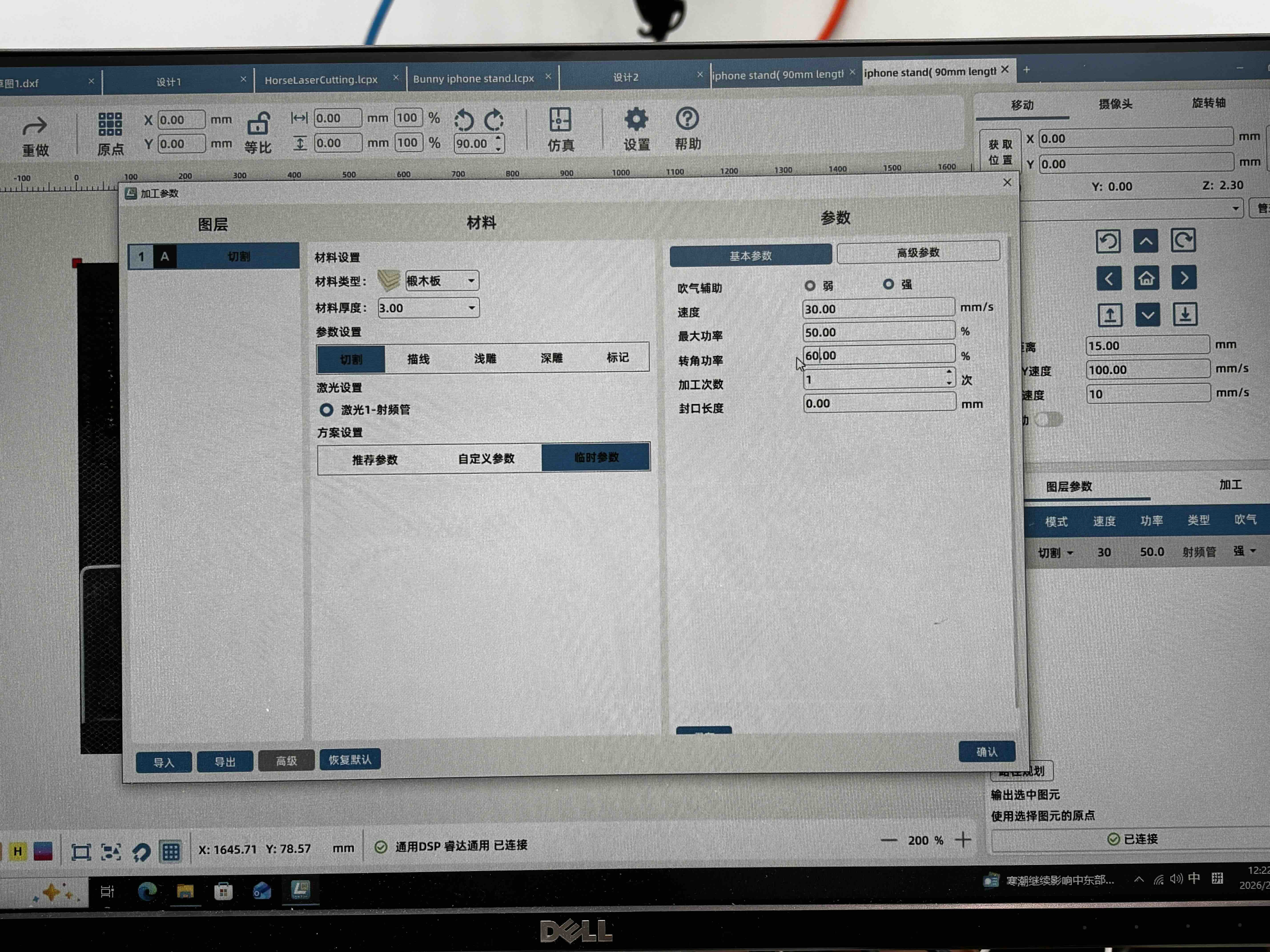
4. Phone stand design in LaserMaker
I also sketched a phone stand in LaserMaker and exported an .icpx file for the Thunder Laser workflow.
Source file
拼插设计Lasermaker.dxf — press-fit kit (DXF export).