9. Input Devices
This week’s goal was to integrate a sensor into a self-designed microcontroller board and measure and read its data. Also watch our progess at the Group Page
Adapting the design and starting production
Before starting the fabrication process, I slightly adjusted my design from week 6.
I added a Button and adjusted the paths slightly.
First, I implemented the schematic and footprint as in week 6.

I connected GPIO10 to pin 1 and pin 4 to GND.
Although this configuration appears somewhat unintuitive in the schematic, it results in a more efficient and cleaner routing during the PCB layout stage.

Now my design looked like this:

I exported it as gerber to start milling the PCB.

While milling the tracks I recognised, they were slightly too small. I cancelled the Job and adjusted the track width.

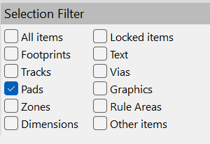
Qick Tipp: With the Selection Filter I filtered the tracks. With CTRL+A and E I edited all tracks at once.

PCB milling
Afterwards, I submerged the PCB in a tinning solution to improve solderability and protect the copper surface.


To keep the design reusable, I mounted the ESP using pin headers instead of soldering it directly. For the next steps, where I need to determine the optimal spacing between the three ToF sensors, I will connect them using wires.

After assembly, I verified the board using a multimeter. Some minor rework was required, as one connection was not properly soldered.
Apart from that, there were no short circuits, and all traces were correctly connected.


With the hardware verified, I proceeded to upload a simple test program to check basic functionality.
For this, I installed the VL53L0X library by Pololu in the Arduino IDE and selected the ESP32 Dev Module in the board manager. To use the serial monitor, I set the baud rate to 115200.
I then uploaded a test program to verify that the button was working correctly.
After confirming this, I uploaded the main code (initially using only a single sensor).
#include <Wire.h>
#include <VL53L0X.h>

VL53L0X sensor;

void setup() {
  Serial.begin(115200);
  delay(1000);

  Wire.begin(9, 8);   // SDA = GPIO9, SCL = GPIO8

  Serial.println("VL53L0X test");

  if (!sensor.init()) {
    Serial.println("Sensor init failed!");
    while (1);
  }

  sensor.setTimeout(500);
  sensor.startContinuous();

  Serial.println("Sensor ready");
}

void loop() {

  int distance = sensor.readRangeContinuousMillimeters();

  if (sensor.timeoutOccurred()) {
    Serial.println("Timeout");
  } else {
    Serial.print("Distance: ");
    Serial.print(distance-15);
    Serial.println(" mm");
  }

  delay(500);
}
It turned out that the sensor consistently measured a value approximately 15 mm higher than expected. As a temporary solution, I compensated for this offset directly in the code by subtracting the measured deviation.
Now I have a first prototype to experiment with.