11. Networking and Communications
Laboratory & Group Work
This week in the lab we learned to communicate between two devices using serial communication. We first networked 2 Arduino Uno boards to commincate with each other and later we attempted communication between 2 bluetooth devices. We also were able to see what a serial data output looks like on an oscilloscope. The results of our work can be found here: Group Link
Useful Files & Links for this Week
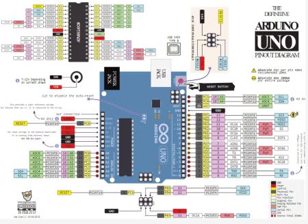
Arduino Uno Pin Map
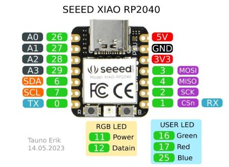
Xiao RP2040 Pin Map
Arduino Uno Datasheet
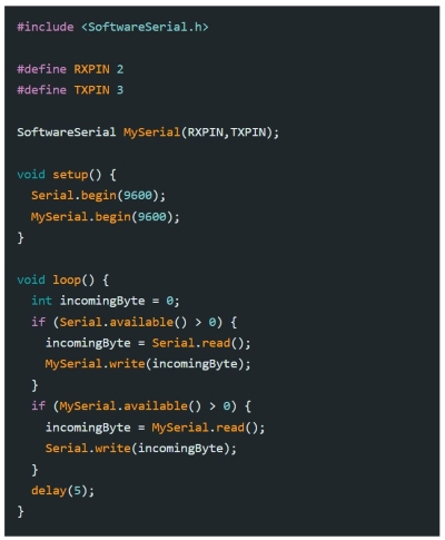
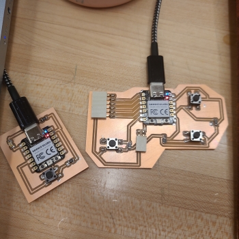
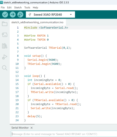
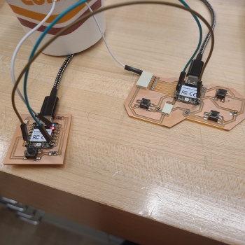
This week for the individual assignment I networked my development board with a classmate's design. She was willing to share her file for a very simple development board she made earlier in the program. Both had a Xiao Rp2040 microcontroller and I used Arduino IDE. My goal was to get one board named the "Serial" board to send a message to the other board "TRSerial" using the serial monitor in Arduino IDE. I could not get it to work with both boards connected to my MS Surface however I downloaded the Arduino IDE software to my home computer and add the Xiao RP2040 to the Board library and it worked just fine with one connected to that computer. It was necessary to cross the wires.....one RP2040's TX pin = 0 and the RX pin = 1 connecting RX on one to TX on on other. Using the code pictured above I uploaded each code separately to each board on each computer. This would allow for the Xiao to transmit a message to the other Xiao using serial communication. The wiring configuration I used is pictured below.
This video is the shortest I could make of one message being sent "hello". I did send several to test it though such as : "Are you still in the fab lab?" and "You should go home, Tammi" It was difficult to take a video using both computers.