10. Output Devices
Group Laboratory Work: Output Device Power Consumption
In groups we explored measuring the power consumption/power draw of output devices with 5 Volt DC fan motor. We measured the power draw of the fan motor when stalled and not stalled by holding/squeezing the rotating pin and again and calculated the measured for power using the formula below. The results of this experiment are in the table below.
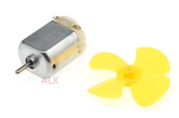
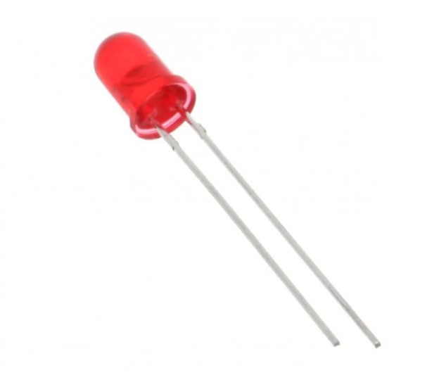
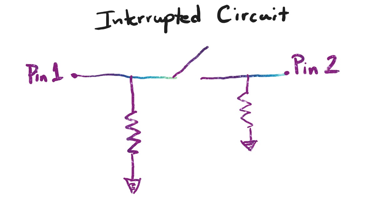
We learned that in order to gain some of these measurements it is sometimes necessary to interrupt the circuit by implanting the positive and negative probes from the digital multimeter within the circuit in order to gain a reading of the current in milli-Amps. See sketch of interrupted circuit below. For example, we also measured the power draw of a red LED as a 5V output device. For this experiment it was necessary for us to interrupt the circuit with multimeter probes. The results from this exercise are also in the table below. Some would have guessed that the power draw for the motor when stalled would be lower if the motor used less energy to turn the rotating pin however, in the end we found that the power draw of the stalled motor was higher because the motor had to work harder to fight the resistance.
For additional notes and photos of our group work click here: Group Link
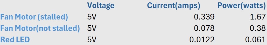
Data from Group Work as Referenced Above
Watts(W)= Volts(V) x Amps(A) *Current is measured in Amps and Power is measured in Watts; calculate amps by dividing milli-Amps (mA) by 1000
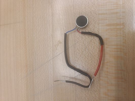
Exploring Mini Vibrating Motors as Output Devices
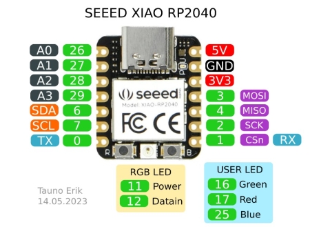
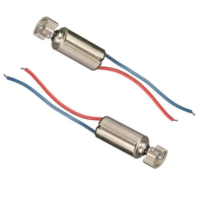
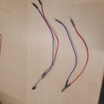
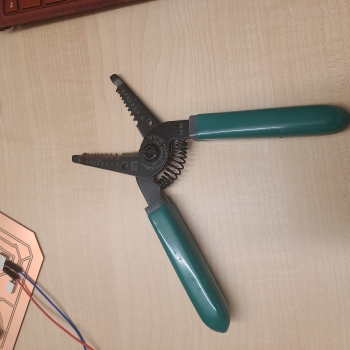
I decided to explore some output devices that could potentially be incorporated into my final project. I searched both Digikey and Amazon for miniature vibrating motors that seemed small enough to fit inside of a standard drumstick. There seems to be several brands of the two types of motors. One is a small button sized motor (actually smaller than a button) and the other is an eccentric rotating mass vibrating motor or ERM. Both of them come in many different sizes so I chose to the order the smallest ones I could find. Standard drum sticks seem to begin at 15mm in thickness while the button motor is 10mm wide. The ERM at 8mm leaves a little more wiggle room and is shaped more appropriately for being placed inside of the contraption. I wanted to test both motors to compare them but to do so I first had to solder jumper wires to both motors since the blue and red wires they arrived with were very thin and very flimsey. Even more importantly they were very short and didnt allow for easy maneuvering. I used a wire cutter to cut and strip the ends of the jumper wires from the lab but had to use an exacto knife to splice the end of the motor wires for both motors and peel the remaining wire coating by hand in order to not damage the thin wires. This was a great suggestion I got from my instructor that worked out perfectly. After twisting the wires to the jumpers, I soldered each connection and then placed heat-shrink tubing over each connection to make sure they were neatly contained. The end result gave each motor about 7 inches of extra length on their 2-wire connections. The red wire would go to power and the blue wire would go to ground and I could use either of the SMD pin sockets, the 2 socket or the 4 socket. I chose to use the 4 socket connection since those gave easy access to pin #4 where there is an output connection on my development board.
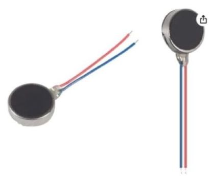
Button/Coin Mini-Motor
My initial thought was to test a few mini-motors since I will use one in my final project.I just needed to find the correct connection pin SMD socket which is wired to the Xiao RP2040. With the first development board I made during electronics production week I was unable to use the motor because of a current issue. Even though it worked just fine I was informed that there would be a current issue if I continued to run the motor while connected to a board that was not constructed for this purpose. I did have to re-solder the 2 pin socket to the development board as the first motor tested shook the socket right off the board...lol. I realized then that I didn't use much solder to secure it to the development board so I reinforced it at our solder station. The ERM motor pictured above is most likely what I will use for the final project as it is slimmer in dimension and has a better chance to fit inside the instrument.
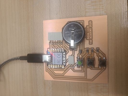
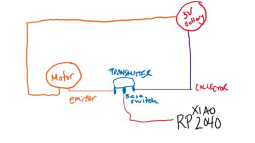
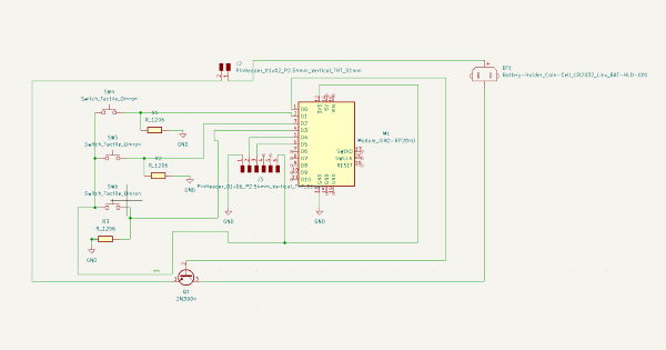
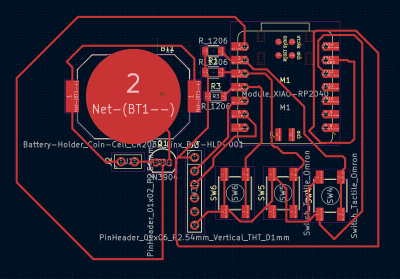
UPDATE:I received feedback from one of the evaluators that was incredibly helpful. The evaluator encouraged me to add a resistor to the development board in order to better regulate electrical current on the board. My instructor also suggested adding a 3V battery to board as well. The need for the transistor arises because the pin from the microcontrollers like the Xiao RP2040 provide only small amounts of current. That current is not enough to directly power the motor from one of the pins on the microcontroller. The transistor acts as a switch to allow only small amounts of current from the Xiao RP2040 to control larger currents needed to power the motor. If I did not add the transistor the output pin on the Xiao could be damaged. Instead, when the output pin is high, the transistor allows current to flow through the button motor and when the output pin is low the transistor switches off and stops the current flowing to the button motor.
I had to connect the base of the transistor to Xiao RP2040 pin. I connected the collector to the 3V power supply and the emittor out to the motor. The positive terminal on the motor is then connected to the 3V battery.