9. Input Devices
Notes from Lab Lecture
In the evening lab session we learned about different ways to read a sensor as input:
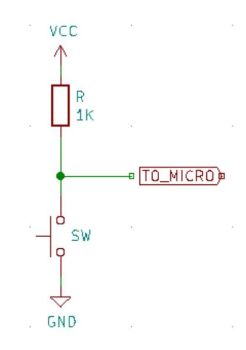
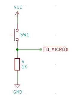
Digital Switch: We learned about buttons with pull-up resistors, pull-down resistors, and built-in pull up resistors as well. We also explored rotary encoders, keypads, and Passive IR sensors as well. Pull up resistors pull the assigned pin to a high state wheile pull down resistors pull the assigned pin to a low state when the input or button is not being pushed. This is a method for controlling voltage. Pull-Up Resistors are connected between the input pin and the VCC (positive voltage supply), while the Pull-down Resistors placed between the digital input pin and the connection to ground. See diagrams below for Pull-up and Pull-down in that order.
Analog Data:
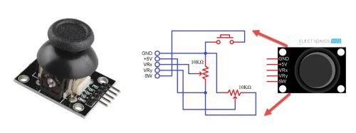
We also explored analog devices as inputs. Specifically we discussed thermistors, photoresisters, phototransistors, and potentiometers both as a volume button and also the analog joystick. Many of the analog devices have the ability the to measure light, sound, temperature, etc. There are also more advanced devices such as microphones, motion detectors, gps, and radar detection. We explored the thermistor and photoresistor more closely which I have documented below in the Laboratory Exploration section. The joystick and the volume knob potentiometer are pictured below.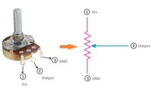
Digital Communications via I2C & SPI: The (I2C) or Inter-Integrated Circuit Protocol allows for serial communication between devices and sensors through a 2-wire interface. It simplifies the connection for displays, motor drivers by using only the 2 wires. The wires send and receive data. The (SCL) or serial clock pin pulses at a regular interval and and sycnronizes the clock of the periphal devices. The (SDA) serial data pin transfers data between the controller and the peripheral devices. If there is one or more peripheral device the devices will take turns communicating since it is just a single line and this makes it possible using only 2 pins on the microcontroller.
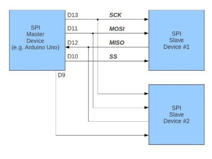
SPI or Serial Peripheral Interface is also a serial communication protocol but SPI is much faster but requires more wiring. The wires for transferring and receiving are separate. It requires 4 wires instead of 2 and while the I2C Protocol allows for multiple masters and slaves the SPI protocol has just one master, meaning only one device can control the bus at any given time.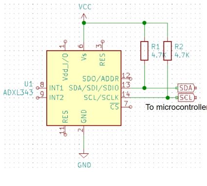
Laboratory Group Work: Probing an Input Device's Analog Levels & Digital Signals
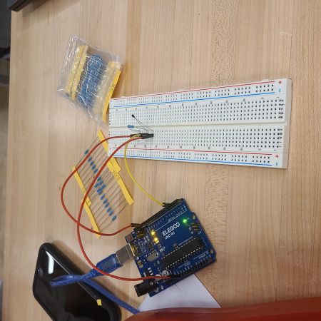
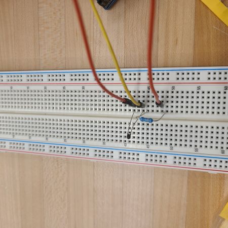
In groups we were able to probe two different types of input devices: a photoresistor and a thermistor as pictured below. For both experiments we used a breadboard, wiring, a resistor, and the Arduino Uno controller board. We were also able to use the same coding for both experiments as both analog devices have two connectors. We were able to very easily remove for instance the thermistor and replace it with the photoresistor. The thermistor measures changes in temperature and the photoresistor measures changes in light.
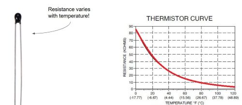
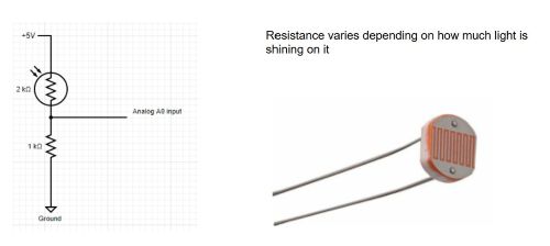
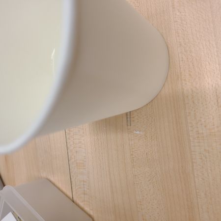
For the thermistor we were able to perform a test by using the heat from our hands to see the analog out put change. It started at 10.667. When we placed our hands over it, it dropped to 6.4. We then placed the resistor under a cup of hot water to raise the temperature and this gave us a reading of 5.9. We also took a tub of ice cream and touched it to the thermistor to see the analog output number increased. As temperatures get hotter the resistance lowers (voltage goes up)and as temperatures get cooler the resistance increases (voltage goes down).
For the photo resistor we conducted simlar experiments using light instead of temperature. The room lights were dimmed and brightened. We covered the photoresistor with our hands to make the area around it pitch black and we also held a light very close to it. In both experiments we could see the analog outputs adjust based on exposure to the condition being meaured. A formula would have to be used in order to calculate actual temperature or lighting accordingly. Below are photos from the thermistor experiment.
Useful Files & Links for this Week
Data Sheet for Xiao Rp2040 Data Sheet for MQ2 Flying Fish Gas Sensor Data Sheet for SMD multi-pin sockets Arduino Site for Xiao RP2040 Github Link to add Xioa RP2040 Update to Arduino IDEAdding a Sensor Input to a Development Board with Microcontroller
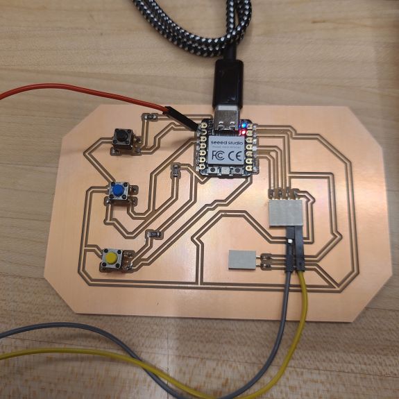
When I initially plugged my development board into the pc this time, it did not power up. I examined all of the soldering and decided to reinforce some connections that looked like they could be made stronger. I did this by using a soldering iron. Most of the reinforcements were needed around the chip. I again tried to power up the development board and it did not work. I heard a crackle and popping noises so I went to disconnect the board from the pc and noticed and that the temperature of the Xiao RP2040 had increased tremendously in just those few seconds. None of the lights illuminated and by the time I uplugged it there was a faint odor of "fried" electronics. I had to return to the lab and mill a new board as removing the rp2040 would make things difficult and could interfere with the performance of the new controller chip. I milled the 2nd genereation of my development board replacing the red and green buttons with a royal blue and black for identification purposes.
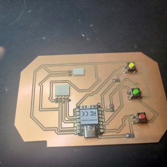
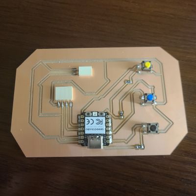
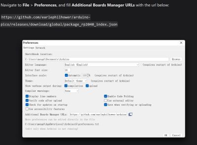
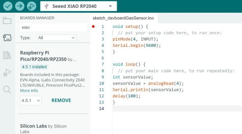
For this week's project I am using my development board to test a gas sensor. I would like to explore how the sensor reacts to different household product gases such as spray paint/stain, smoke from burning wood, the gases in an aerosol can of cooking spray, and fumes from an automobile's gas tank. Since my development board has a Xiao RP2040 I needed to visit the documentation page for the manufacturer since the library of boards on my Arduino IDE only had expired versions. I followed the directions on the Seeed website to download a new and working version for the Xiao RP2040. Without this version it would be impossible to upload the code from the pc onto the chip itself. Using the same code we had used in the pass for blinking the on-board LED I kept receiving an error during the upload stage as the computer was not recognizing that the Xiao RP2040 was connected. I followed the instructions on the documentation website to add the board's new package file to my IDE. Once that was complete I rebooted the RP2040 following the instructions on the documentation site. See screenshots below.
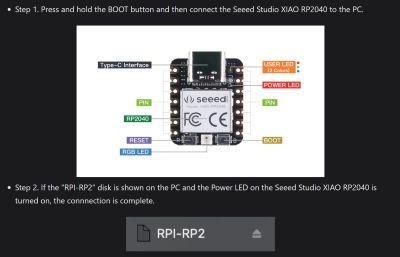
I rebooted the rp2040 by holding down the onboard reboot button as presented in the above instructions. While holding the button down I connected the development board to my computer. This allowed the computer to recognize the chip as a drive to where data and programming can be sent. I continued to hold the button and ran a verification check and was finally able to upload code to the rp2040 as this controller board was now available in the selection menu.
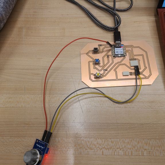
I needed to use a few different data sheet images to guide me setting up the wiring for this assignment. These allowed me to know the function of each pin and trace on the development board. The sensor was connected to the development board through the 4-pin SMD socket. The datasheet layouts for each of the maps are below including the pcb layout of my development board which clearly labels the traces and connections.
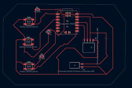
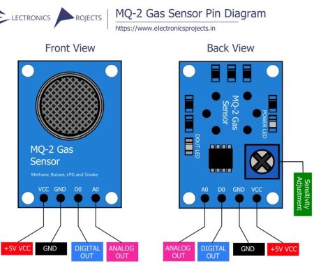
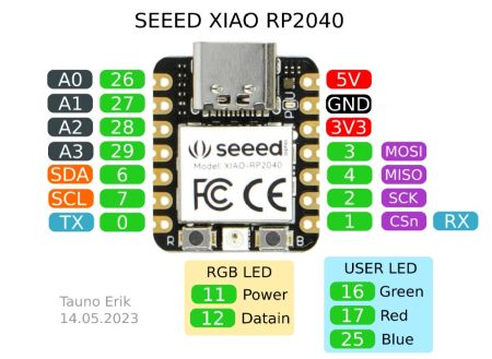
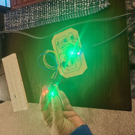
It is important to note that before the reboot I was able to connect the sensor to the development board and powered up both boards by connecting them to the pc. All onboard lighting on both chips illuminated. For the sensor chip both the power light and the data out light light were illuminated. For the Xiao rp2040 all lights were illuminated and performed their standard blinking behavior. By engaging the black tactile button the green LED on the Xiao rp2040 would dim.
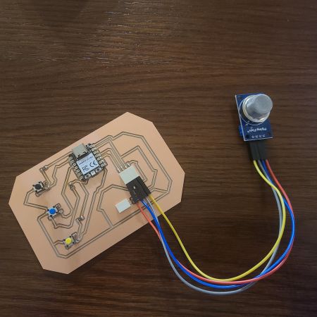
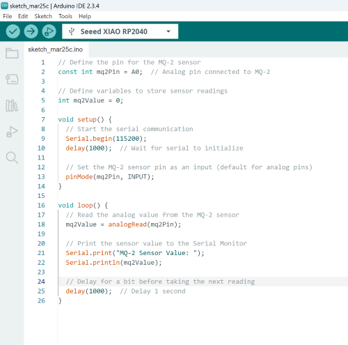
In performing a google search I found quite a few different approaches to the coding for these connections. Most coding that I discovered was for a more complex setup with external LEDs, digital output devices such as LCD screens, etc. The two that I believed would potentially work seemed to allow use of a 3rd party board similar to my development board, didn't require a breadboard connection, and one looked very similar to what we used in the lab for both the thermistor and the photoresistor. The other was discovered on the Arduino documentation site when I googled "connecting a gas sensor to the Xiao RP2040". Screenshots of the code are below. The one on the left is a simple code; the same one as used with the thermistor and the photoresistor. The one on the right is the one I finally ended up using for the Flying Fish MQ2 gas sensor.
After the reboot I took note of a change in the lighting. The DO or data out light on the sensor was no longer illuminated and the multicolored larger blinker on the RP2040 chip was no longer illuminated. I assumed these lights would illuminate again once the sensor is activated by gas exposure and has some data to tranfer an output display device. I again tried to verify sample code which completed. I moved on to the upload stage and that completed fine as well.
With my instructor's help I was able to test the sensor on another computer using the Arduino Uno and it registered several different reading both with human breath and fumes from hand sanitizer. This showed us that there was specifically a challenge with the analog out connection from the sensor and how it was meeting the development board. My instructor also figured out that the Arduino IDE was set to the wrong COM port to receive information from the USB connection. We used the tools menu to find the options for COM port numbers. By plugging in and then removing the usb connection I was able to see that the COM port the development board was using was COM15, not COM 2 as had previously been selected. This of course was complete game changer. In my research on the information packet for the Xiao RP2040 revealed that most of the open pins on the Xiao RP2040 could be used for both Analog and Digital connections.
With additional guidance from my instructor I discovered it seemed that the sensor was connected correctly and the coding was correct, however the sensor was still not making a reading. The output remained at steady 12 or 13 and went back and forth between the two numbers. My instructor suggested moving the Analog out connection to the opposite side of the controller board by using the A0, A1, A2, or A3 pins. I unfortunately used A0 and A3 to connect my buttons, however A1 was unused. My board was not designed to receive an analog input on that side of the board from an external component so rather than redesigning the board I was able to push a male-ened connector wire into the pin hole for the A1 pin. This allowed the sensor to begin working and print data in the serial output panel. I first saw a reading of 12 or 13. Fumes from the hand sanitizer increased it substantially to the upper 50s, but interestingly enough in this initial test my human breath raised the reading to between 79 and 82! See data below!
Final Working Connections
The VCC pin from the MQ2 out to 5V on the Xiao RP2040
The GND pin from the MQ2 out to GRND on Xiao RP2040
The AO or Analog Out pin from the MQ2 out to the A1 on the Xiao RP2040
Rustoleum Paint Test Video
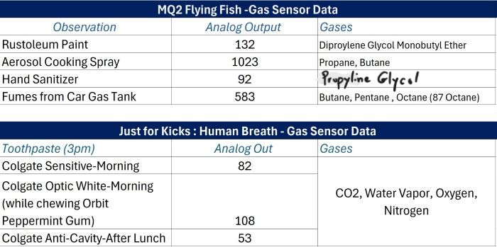
My assumption was that the Rustoleum Paint reading from the gas sensor would be off the charts as compared to humans breathing into the sensor. Oddly enough the highest reading it registered was 107, while a human chewing Orbit peppermint flavored gum (a fresh piece) maxed out at 108! Those not chewing gum gave readings between 58 and 82. Since the can of rustoleum just had the lid off, I decided to paint a few strokes onto wood to see if I could get an increased reading. The reading for Rustoleum increased to 132. The tables below include several readings and description about how the information or observation was made. The analog readins are interesting but of course it is tough say what the numbers actually mean since the device reads certain gases and not others and there is no way for me to know which gases influence the sensor or to what degree when they are mixed with others. Either way, I am fascinated that the pam cook spray was the highest possible reading of 1024.
