4. Embedded Programming
Cloning the Group Git Repository
This week we were split into groups and I am working with Gillian, Hannah, & Sierra S. In order for us to work together we needed to clone the group repository so I needed to review the cloning process since it had not gone so smoothly during week 1. With my teammate's assistance I was able to clone the group repo very easily by visiting the Gitlab projects tab and clicking on group assignments. I then clicked on the blue box down arrow that says codeand then copied and pasted the SSH clone link. Next I visited the gitbash interface and used the "git clone" command followed by SSH code I had copied and pressed enter. By cloning this repo we will be able to work on editing the same files and can share work with each other. It will be necessary for us to pull from the repository to receive the latest updates to the shared pages as well as push to the repository in order to share our changes made. Our group assignment page can be accessed here:
New Key Terms from Class Notes:
Toolchains: a set of programs on a computer that let you write programs for an embedded system, compile them into a format a microcontroller can read, and send them to the microcontroller chip.
Architectures: family of microcontrollers that share a common internal structure. Code written for one architecture won’t work on a different one, and some architectures may be more capable than others.
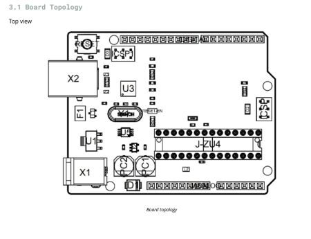
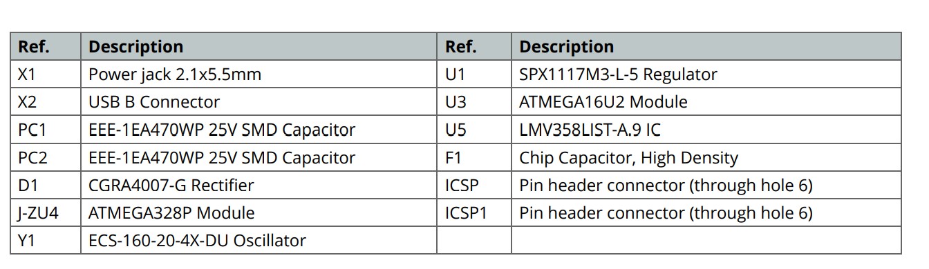
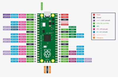
The data sheets for the microcontrollers have lots of useful information but what I found most useful was the layout of each chip with the list of things that could be found on the chip along with their functions. Below is an example of the Topology Map from the Arduino Data Sheet for the Arduino Uno. As you can see the datasheet for the Pi Pico also has a similar useful topology map.
Arduino Data Sheet Topology Map
Raspberry Pi Pico Topology Map
Practice Using Wokwi Simulator
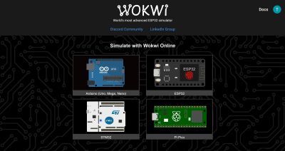
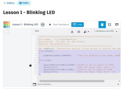
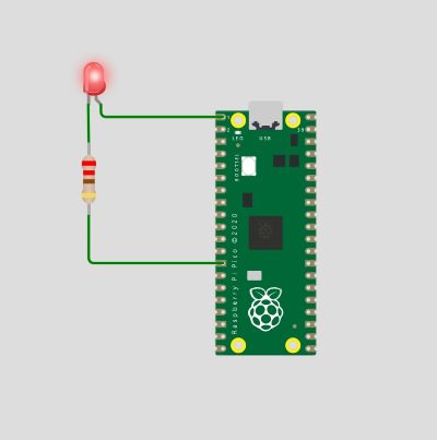
During class we were introduced to the Wokwi online simulator. This online simulator can be used to simulate Arduino Uno, Raspberry Pi Pico, and other boards to interact with inputs and outputs such as buttons, switches buzzers, etc. For the first Wokwi simulation we sketched the Raspberry Pi Pico and connected it to a red LED with the intention of making the light blink. I was able to find the appropriate Arduino IDE code using the Tinkercad Lesson Gallery as pictured below. I was able to copy and paste the code into Wokwi on the coding side of the interface but on the simulation side I needed to create a "sketch" of the electronic parts to be used. For this simulation I used the Raspberry Pi Pico board, a red LED, and a resistor. I chose the resistor and the red LED from the add menu by clicking the plus sign. On that menu there are many outputs and inputs available which I will experiment with later. I was then able to drag and drop both the LED and the resistor to locate them in such a way that they would be close and connectable by wire to the controller board.
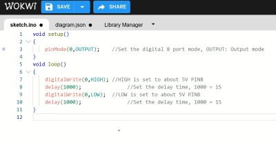
I changed the resistor value to 220 ohms and the colored stripes changed to confirm that adjusted value. 220 ohm resistors are often used to protect delicate electronic components, control modest currents, and most importantly offer steady voltage levels. I then clicked on the ends of each componenent to add connection wires. I ran one wire from GP0 to the anode and I ran one wire from the cathode to the resistor. I connected the other end of the resistor to the GND3 for grounding. The wires were added by clicking on the end of each component and dragging the wire to the proposed location. Once adding the wires into the sketch you can double click them to change colors. For instance grounding wires are usually sketched in black and once we are working on more complex setups the colors of the wires will become more important. For these sketches I kept them green.
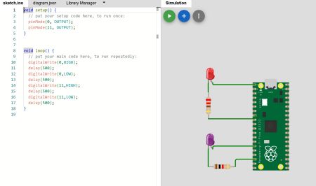
After adding all the wires, I clicked on the "play" button and was able to see the LED blink about 1 time per second. I later adjusted the delay down to 500 and the light blinked even faster. The lower the number in the delay code, the faster the light will blink. I also ran a similar simulation running two different LEDs simultaneously. It required me to take the code provided above and add some additional lines and pin designations, in addition to one more resistor as pictured below.
Overall the wokwi online simulator seems incredibly useful for testing purposes in two ways. First you can make sure that the code you've written actual works and second before soldering any permanent connections you can make sure everything was connected properly using the simulator and perhaps save some time and materials from being wasted.
Useful Links
- All Things 220 Ohm
- Mu Editor
- Wokwi Electronics Simulator
- Arduino IDE Tutorial for Pi Pico
- Arduino IDE and Arduino Uno Built-in Light Tutorial
- Tinkercad Tutorial Pi Pico Blinker
- Arduino Uno Data Sheet
- Raspberry Pi Pico Data Sheet
Group Assignment for Embedded Programming
As a group we attempted 3 embedded programming tasks:
1. We programmed the Arduino Uno chip using the Arduino IDE toolchain
2. We programmed the Rasperry Pi Pico board using the CircuitPython toolchain
3. We programmed the Raspberry Pi Pico using the Arduino IDE toolchain.
We have documented our activity at the following link: Our Group Link
Exploring the Arduino Uno on My Own
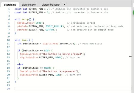
I decided to explore the Arduino Uno controller some more after learning about the Raspberry Pi Pico. Wokwi also has the Arduino Uno Board which I learned about in our group assignment but now I was curious to try out some of the add-ons available in the menu to be used as outputs and inputs. Below I describe how I connected a push button as an input to the Arduino board to create a buzzer noise as an output. The buzzer can be found on outputs list when you click the plus sign to add a component. The button can be found on the list of basic inputs. I found a tutorial for sketching and coding this experiment by performing a search on google for "arduino uno buzzer with button wokwi" and was able to find code to fit the input and output components I had chosen.
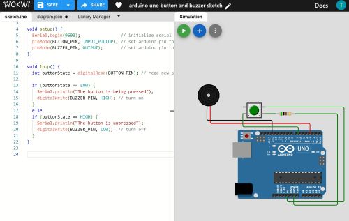
As detailed on our group assignment page we worked with the Arduino Uno and its on-board LED. For this experiment I was connecting a button to an audio device. I was able to find the appropriate Arduino IDE code using the wokwi projects tutorial found in the search that I described above. I was able to copy and paste the code into Wokwi on the coding side of the interface but on the simulation side I needed to create a "sketch" of the electronic parts to be used. For this simulation I used the Arduino Uno board, a green push button, a resistor, and an output device that plays sound. I chose the resistor, the green button, and speaker from the add menu by clicking the plus sign. I was then able to drag and drop the button, speaker, and the resistor to locate them in such a way that they would be close and connectable by wire to the controller board.