3. Computer-Controlled Cutting
Fab Lab Safety Protocols and Training
Our instructors reviewed the safety protocols for the large-scale vinyl cutter and the laser-cutting machine. For the vinyl-cutting machine, users should be careful of their hands and be sure they are clear of the machine as it starts cutting. While weeding the designs, it is sometimes necessary to use sharp tools or implements to remove the excess vinyl from your design. As such, users should be careful around other students while keeping all implements away from faces, etc. When one is done working the workspace should be left as it was found.
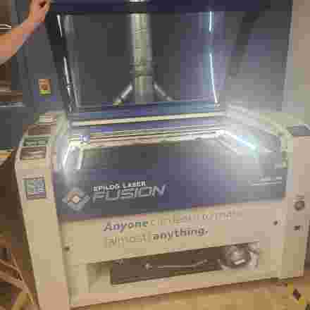
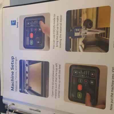
For the laser cutter, there is a bound instruction booklet that displays pictures on a step-by-step basis of how to set up the machine safely before using it. The machine should only be used if there is more than one person in attendance at the fabrication lab as all the materials are flammable and being treated with a heated laser. In this case, the buddy system works best in case of an emergency. Things most notable in this part of the training were how to turn on the exhaust system that must be run while cutting and of course, the emergency off switch to stop the machine in the case of emergency. The machine can also be stopped by opening the hood and this usually works quicker than the emergency stop button. To protect the eyes, we should not stare directly at the laser at any time to avoid damage to our vision.
Key Terminology for the Basics of Laser Cutting
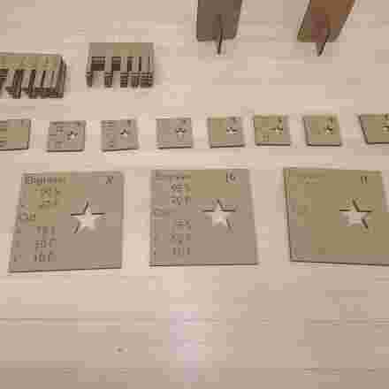
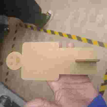
Engraving/Rastering is the process of marking the surface of materials without fully passing through it (see cardboard man’s smiley face below). Vectoring is the process of fully cutting through the material (full cut). Speed measures how fast the laser cutting head will move during the cutting process while power is a measurement of how much energy the laser will provide during the cut. Higher power causes the material to heat more quickly. Frequency tells the speed of the laser cutter’s pulsing motion between on/off states when cutting/vectoring. It’s best to use higher frequency when using materials that are heat-sensitive.
Air Assist is a setting that is ALWAYS engaged for rastering and vectoring as it pushes air through the laser cutting head. This feature clears the cutting area of smoke and debris and also keeps anything from accumulating on the laser cutting head.
Settings and Characterizations for MK1 Laser Cutting Machine
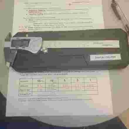
We examined Kerf Combs to implement average kerf calculations for our Epilog Fusion MK1 120Watt Laser Cutter. The calculations are appropriate for using cardboard like that pictured in the kerf comb below. We used digital calipers like the one pictured below to calculate our average which was 0.30mm.
We used the following settings as they seemed ideal for this machine:
Engraving/Rastering Settings: Speed 95, Power 15
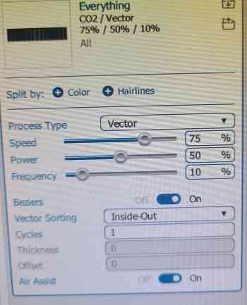
Vectoring/Cutting Settings Speed 75, Power 50, Frequency 10
Vinyl Cutter Exploration
MK1 - Laser Cutter
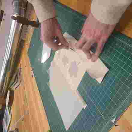
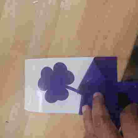
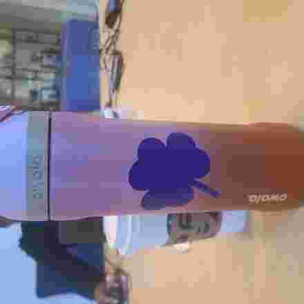
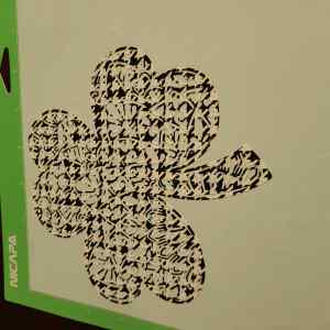
During this week’s lab, I experimented with industrial Vinyl Cutter in the Fab Lab. I was a little more familiar with this type of cutting as I own a Cricut Maker 3 at home and have been trained on the industrial cutter recently on campus. The machine itself is straight forward and we learned from our instructor about the different types of vinyl, t-shirt transfers, and various types of sticker paper. We also learned how to use the rollers to line up the roll of vinyl as we load the machine. I chose to cut purple shamrock as a method of ID-ing my Owala water bottle since many of us have them on campus. For this, I used purple permanent vinyl and was able to weed the background vinyl by hand since the shamrock was relatively simple in design. I did, however, need to use a scraper to apply the vinyl to the water bottle without leaving any air bubbles behind. After removing the background vinyl, I transferred it using a large masking transfer tap. Please see below for the pictures while in progress as well as the final project.
We determined the appropriate settings for the Vinyl Cutter to be : Speed-108 and Force-60
Cricut Maker 3 Cutter
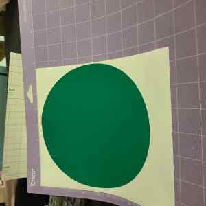
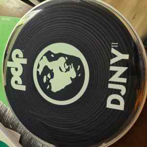
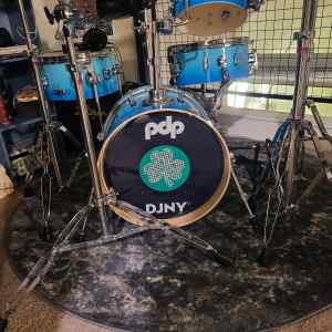
I decided to experiment a little further with the vinyl cutting at home since the shamrock on the water bottle was a rather simple design. I decided to try something I haven't done before which was to layer vinyl on top of vinyl. I used cricut design space to draw a green circle the exact circumference of the image on my kick drum which I've been unpleased with for a while. I knew that green would cover the image well even though the vinyl was not very thick. I used a shamrock design from cricut's repository that required a ton of weeding but knew that this would allow some of the green from the circle to show through it. The weeding combined with the houndstooth plaid vinyl made for great coverage of the image on the original drum head. Hopefully Daru Jones, the great drummer for whom my drum kit was designed for, will not find my St. Patrick's day obsession too offensive as I am covering his face with it...LOL. The green circle was cut at 7.25 inches and the shamrock design was 5.75 inches. It was necessary to apply the first layer, the green circle, before attaching the shamrock to the resonant head to make sure there would be a flat surface to receive the shamrock. Tranfer Tape was not necessary for the green circle but I did use a debit card as a scraping tool. I did, however, use transfer tape for the shamrock as it was very delicate and the transfer tape made the design stable enough to transfer onto the flat surface, also using the debit card as a scraping tool. I think the end result came out great and I no longer have to feel as though the strange face on the original drum is looking at me every time I walk by!

In experimenting with the two different vinyl cutters, I can definitely say that the industrial vinyl cutter makes larger jobs much easier, the machine works much faster, and is directly connected to the workstation. The learning curve, however can seem quite steep if you have never used the machine before. I think in general I prefer the US Cutter Industrial Vinyl Cutter as many of the cricut machines seem to have connectivity challenges with bluetooth and these challenges can make a job require longer than estimated to complete. The industrial cutter, however is typically not something you would find in the average home and so the cricut is great in a pinch in that particular case. It worked fine with this project.
Parametric Design Exploration V.1 with Cricut Maker 3
This is the perfect point to segue into my notes on parametric design which is a continuation of the discussion above which detailed my training on the MK1 laser cutter. In designing this week’s construction set I was unable to travel to the lab so I decided to pursue this project using my Cricket Maker 3 in order to attempt the project by the deadline and with the full intention of repeating it later in the week using the MK1 laser cutter.
This was an interesting and exciting journey since my Cricut has only been used for vinyl projects and t-shirt transfers. I had no idea it could be used to cut all kinds of materials including cardboard and wood veneer. I only had access to limited materials so for this project I used cardboard snap board to create the prototype for a parametric construction set.
Materials Used: 3 sheets of 8.5 x 11 snap board, one cricut weeding tool, one cricut adhesive mat, and the Cricut Maker 3 machine.
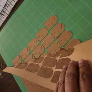
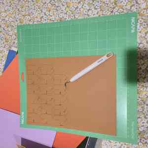
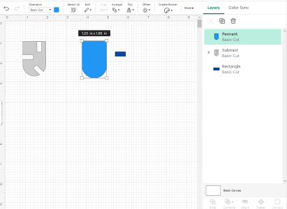
I chose the pennant shape that you see in the pictures below which originally had no notches. This was an outstanding discovery because I had never sketched or edited shapes in the Cricut design space so I learned a new skill. After choosing a general shape I was able to add rectangles as notches and the design space has a feature where you can combine all the shapes and then remove the notches or cutouts. This seemed to work very easily and you can use your mouse to adjust the measurements. The Penants that I cut ended up being 1.55 x 1.75 inches and I added one horizontal notch, one vertical, and one on the diagonal to make things interesting. The thickness of the snapboard was 0.03 inches so after some trial and error I determined that due to the kerf (about .005 inches) and so I subtracted this number from the 0.03 to make the notch smaller by the “average” kerf. This would ensure that the pieces would fit snuggly together and also took into account that snapboard is considerably thinner than cardboard. It worked out well that the paper manufacturer specifications were in inches and so was the default measurement on the Cricut Maker 3. As seen in the pictures below, I was able to cut several pieces but since I was using snapboard I needed to use a weeding tool to completely remove the notches that were cut by the machine.
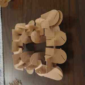
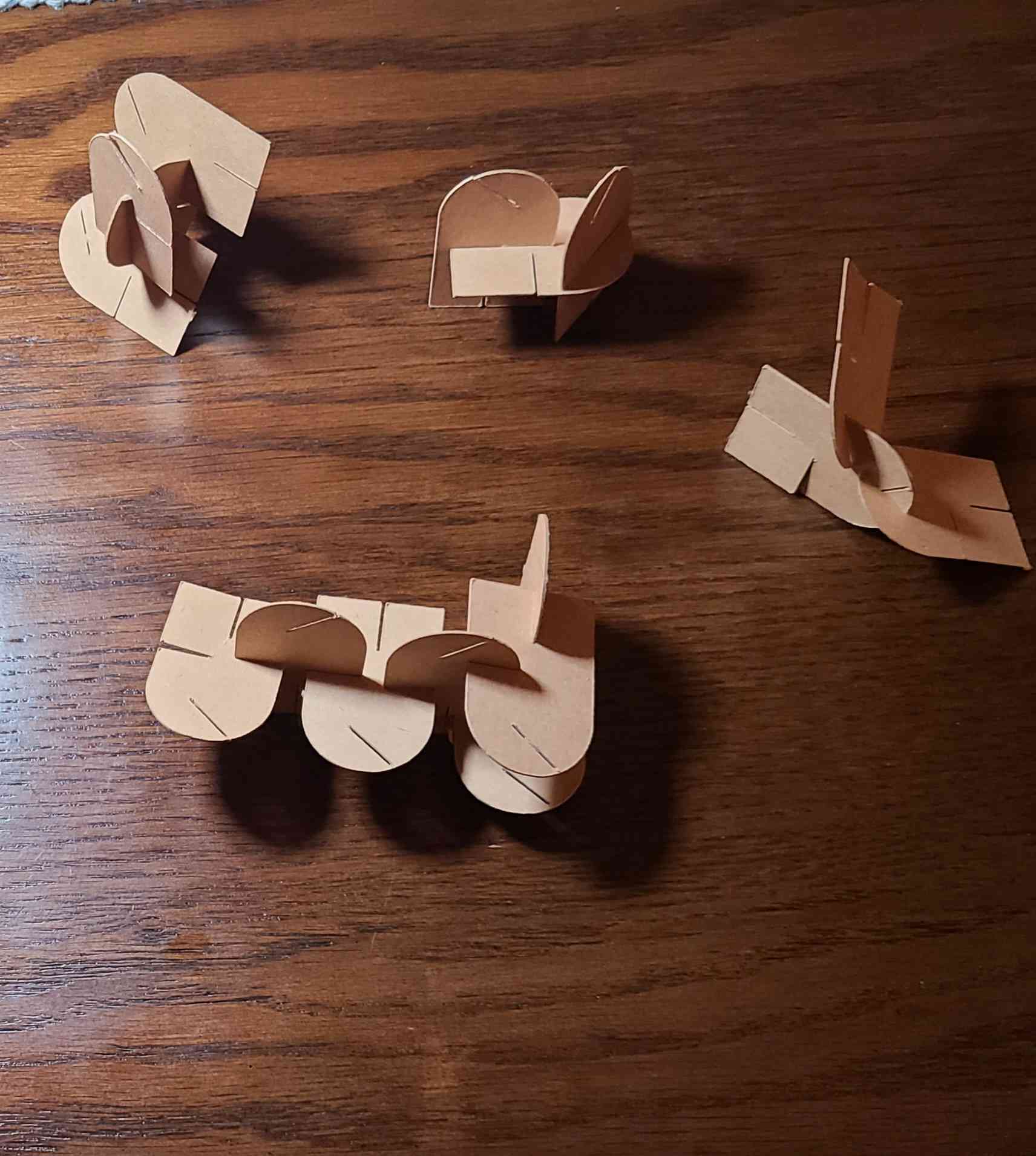
I assembled a structure that very much looks like a maze or type of square labyrinth. I also took a photo of several different connection approaches that can be used if I decide to make these pieces out of a different medium such as clear vinyl, plastic, thicker cardboard, etc.
My original intention was not to do this on the Cricut and so I had limited materials to work with. I returned to the lab later in the week and was able to replicate this work with a thicker material. I had already begun to sketch and measure in the meantime so that I would arrive prepared to cut with the thicker cardboard which we tested to have an average kerf 0.21. I was hoping they would look similar to the sketches below. But time required otherwise and I describe that adventure below.
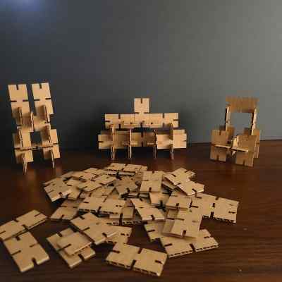
Parametric Design Exploration V.2 with MK1 Lasercutter
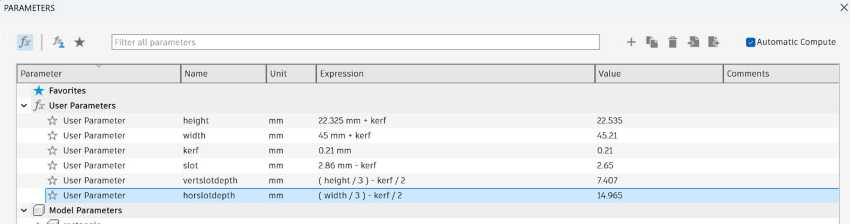
I returned to the lab later in the week to repeat a similar excercise with the MK1 lasercutter. The Fusion 360 software certainly has more features and functions when it comes to parametric design as far as I am aware. Since we were already moving into the next week's topic I chose to go with a basic rectangular designed piece with 4 notches in order to save time. I believe this very simple design allows for lots of flexibility in building several different types of structures using identical pieces. Off the top of my head I was thinking it could be used to build mazes, towers, rectangular archways, tiny houses, larger boxes, etc. In Fusion 360 you can be sure that your design is parametric by adjusting the length or width of any chosen dimension and the entire shape should shift in proportion to the change you've made. This was a great feature that I don't believe the cricut machine has. The table below captures the dimensions of the final piece and formulas used to account for kerf. These adjustments were made by dividing the kerf by 2 to insure a snug fit for each piece.
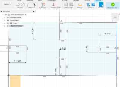
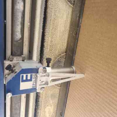
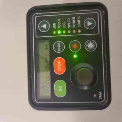
I first revisited our Lasercutter's safety guide which had very detailed instructions with pictures of how to operate the machine and all of it's safety settings. I did note during our lecture that for this machine if you are using Fusion 360 you must export your file as .Dxf file in order to be able to open it for lasercutting. Once the file is exported it can be opened on the lasercutter workstation as an Adobe Illustrator file. The first thing I did when opened the file was set the units of measurement so that 1 unit would be equivalent to 1mm. Some of the features that were similar to cricut in the Adobe Illustrator software was the units of measurment set up adjusting replication and copying in order to make many pieces. The settings and characterizations used are detailed above in the training section but they can be seen here again in the print/cut menu in adobe photoshop. Using the jog function and the focus function in conjuction with the small joystick style controller which can be seen in the picture below allows for us to move the laser into starting position to the far top left corner and also allow us to raise the print bed of the laser cutter to the right height which is noted by the silver guide in the photo below. It helps us set the cardboard or wood in a way that it is not to close to the laser cutting head.
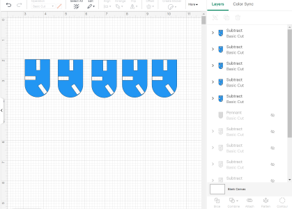
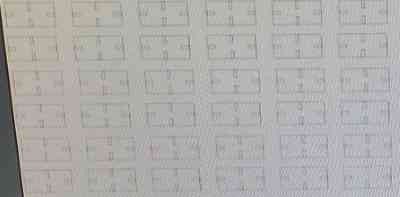
Below pictured are the shape from above as the were cut using the MK1. As mentioned aboved I used a cut and paste function in order to replicate the pieces in Adobe illustrator and then set the characterizations summarized above for power, force, and speed. These numbers can be changed in the print menu as pictured below. The final pieces can be used to build several type of structures and I believe someone could enjoy creating several type of platforms, bridges, towers, and rectangular archways of all kinds. In the end the thicker cardboard pieces are much sturdier than the ones made of chipboard on the cricut allowing for the structures to be made of more pieces while remaining sturdy!
Design Files for this Week
It seems I can only provide a cricut link to share to my files without having a membership. I am unable to save the files to my local computer. Sadly I believe a membership may be necessary to access the links as well, but I've shared them here for those labs who may have a cricut branded machine.
Parametric Construction Piece Cricut File for Penant Piece Cricut File for Shamrock Graphic