3. Computer controlled cutting
Summary

Group assignment
Laser cutting
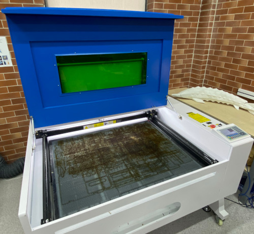
VOIERN 1310 RD Laser Cutting Machine
The VOIERN 1310 RD is a high-precision CO₂ laser cutting and engraving machine designed for processing a wide range of materials. Thanks to its versatility and reliability, it is suitable for both professional use and small workshops.

Key Features:
- Working Area: 1300 mm × 1000 mm — allows processing of large-sized materials.
- Laser Type: CO₂ laser with a power of 80–100 W (depending on the model).
- Positioning Accuracy: ±0.01 mm — ensures high detail in cutting and engraving.
- Cutting Speed: Up to 600 mm/s — increases productivity.
- Supported Materials:
- Wood, plywood, MDF.
- Acrylic.
- Leather, fabric, cardboard.
- Paper, glass (engraving), ceramics (engraving).
- Cooling System: Water cooling — ensures stable laser operation.
- Software: Compatible with popular laser cutting and engraving software such as LaserCAD, RDWorks, and LightBurn.
- Interface: USB, Ethernet — convenient connection to a computer.
Advantages:
- Large Working Area: Enables processing of large workpieces.
- High Precision: Ideal for complex projects requiring fine detail.
- Ease of Use: Intuitive controls and setup.
- Reliability: High-quality components and stable performance.
- Versatility: Suitable for a wide range of materials.
Applications:
- Cutting: Creating decorative elements, models, and templates.
- Engraving: Applying logos, text, and images to various surfaces.
- Production: Manufacturing packaging, promotional items, and souvenirs.
- Education: Used in educational institutions for teaching laser technology.
Why Choose VOIERN 1310 RD?
- Quality: High-quality components ensure durability and stable performance.
- Flexibility: Suitable for a wide range of tasks, from hobbies to industrial production.
- Support: Easy-to-use software and detailed documentation.
Software
The software we use for aligning and operating laser cutting is called RDWorks. When running our laser cutting tests, we imported our SVG files into RDWorks and edited them according to our specifications for the current task.
Cardboard test

Power + Speed test
The 2021 Waag class used a matrix to test the varying effects that happened across different speed - power combinations. The SVG file for our test is listed in my Digital files at the bottom of the page.

Test Kerf
This week I performed a kerf test to understand how much material the laser removes while cutting. This value is important for designing press-fit joints and accurate parametric models.

First, I designed a 20 × 20 mm square in CorelDRAW and exported it to the laser cutter.


After cutting, I measured the actual size of the piece with a digital caliper. Instead of 20.00 mm, the result was 19.60 mm, which means the laser removed some extra material along the outline.
To calculate the kerf, I used the formula:

So the kerf of this machine and material combination is approximately 0.20 mm.
Knowing this kerf value helps me design more accurate laser-cut parts and adjust my parametric tolerances. I also considered this kerf when designing my press-fit kit to ensure a tight and reliable fit between all components.
Individual assignment
Laser cutting
I wanted to design a phone stand using a laser cutter. Since this was my first experience working with laser cutting, I began by planning the structure of the stand and creating its CAD model in Fusion.

I opened Fusion 360 and created a New Design to start modeling the phone stand.

I selected a base plane to begin sketching the main shape of the phone stand.

I drew a rectangle sketch and defined its dimensions to match the required size of the phone stand.

I continued refining the sketch, adding detailed dimensions for all parts that would later be cut.

I extruded the sketch to a height of 3 mm to match the thickness of my material, creating solid bodies for the stand components.

I positioned the stand pieces in 3D space to visualize how they would be assembled.

I selected the sketch and exported it as a DXF file, which is required for laser cutting.

I saved the exported DXF file to my computer so it could be sent to the laser cutter.

I then imported the DXF file into CorelDRAW to make final adjustments to the sketch before laser cutting.

In the sketch, I added slots so the two parts could interlock. These slots were originally designed for 3 mm plywood, but the material we had was slightly thinner. I measured the actual thickness with a caliper and found it to be 2.7 mm, so I modified the DXF file accordingly.

I moved the parts closer together to reduce spacing and save material during laser cutting.

Next, I exported the file for laser cutting.


I opened the RDWorks software to cut the DXF file from plywood and imported the DXF into the program.


I then prepared to send the file to the laser cutter for processing.

I aligned the laser head with the material using a plastic spacer with a thickness of about 1 cm, and then I started the cutting process.


Cutting process in progress.
Here is the result after cutting. Next, I assembled the two parts together.

I assembled the two parts, and the result turned out nicely. I was very happy with how it came out.


Parametric Design in Fusion
This week, I focused on creating a parametric design in Fusion 360 and preparing it for laser cutting. My goal was to design a simple geometric model where the dimensions could be easily changed using user-defined parameters. After completing the design, I exported the sketch as a DXF file, which is the required format for laser cutting.
By using parametric modeling, I can quickly adjust the diameter, the number of segments, or the slot width—without manually editing the sketch. This approach saves a lot of time when preparing parts for fabrication.
Below is the full process with explanations for each step.

Here I created custom parameters using the “fx” Parameters tool in Fusion 360. I added a parameter named extrude with the unit mm so I could control the extrusion height later. Defining parameters at the beginning makes the whole model fully adjustable.

In this step, I used the parameter extrude when performing the extrusion operation. Instead of typing a number, I simply typed the parameter name. Fusion automatically applied the predefined value (3 mm). This ensures that all features update correctly when parameters change.

This is the result of the parametric model—six identical slices arranged in a circular pattern. All dimensions are controlled by parameters, so if I change any value (diameter, thickness, or number of pieces), the entire shape updates automatically.

Here I modified the value parameter in the Parameters window. Once updated, Fusion 360 automatically regenerated the geometry. The red arrows show which parts of the model changed according to the new parameter values.

In the final step, I exported my sketch as a DXF file. This format is required for laser cutting. I selected the sketch, chose DXF Files (*.dxf), and saved it to my computer. This file was then used on the laser cutter machine for fabrication.

In this photo, I am measuring the material thickness with a caliper. Then I updated the parameter named material to 5 mm and re-exported the file. This step is important because the material thickness directly affects the laser-cutting parameters such as speed, power, and number of passes. Accurate measurement ensures a clean and precise final cut.

Here, I am importing my DXF file—exported from Fusion 360—into the laser cutting software. This is where the digital design transitions into the machine workflow. The highlighted area shows the file selection window before loading it onto the workspace.

In this image, I arranged all parts of my parametric design onto the laser’s workspace. I positioned the shapes efficiently to save material and minimize waste. This layout was generated from the parametric model I created earlier in Fusion 360.

This photo shows the parameter window where I configured the cutting speed, power, and other essential settings for my material. Choosing the correct parameters is crucial when working with different materials to ensure good edge quality and avoid burning.

Here, I am setting the correct laser focus distance by adjusting the head manually. Proper focusing ensures that the laser beam hits the material at the optimal point, resulting in sharper cuts and higher precision during the entire process.

In this photo, I pressed the “Start” button to begin the laser cutting job. At this stage, the machine follows the toolpath generated from my DXF file and starts cutting the shapes exactly as designed.

This image shows the laser machine in action. I am cutting my parametric circular parts, which I modeled and exported earlier. You can clearly see the clean cut lines forming on the material as the laser moves across the surface.


After cutting all the parametric pieces on the laser cutter, I assembled them into a 3D structure to test how well the slots fit and how the geometry behaves in physical form.
Notes
In the group assignment, we measured the kerf of our machine. However, in my individual assignment this week, I did not use the kerf value directly.
The reason is that RDWorks automatically applied its own default kerf/compensation settings, and I relied on those built-in parameters. Instead of manually adding kerf as a parametric value, I adjusted only the material thickness (as shown in the photos), making sure the digital model matched the real sheet thickness.
For this week’s task, the default RDWorks settings were sufficient, and the parts fit correctly without extra kerf tuning. In future assignments, especially for more precise joints, I plan to integrate the kerf value into my parametric design for better accuracy.
Vinyl cutting

TENETH cutting plotter is a high-precision device designed for cutting various materials such as vinyl, paper, and film. It is widely used in advertising, design, and production industries. The plotter ensures accurate and smooth cutting due to its advanced servo motors and precise control system. It supports various file formats and can be connected to a computer via USB or other interfaces. The device is equipped with an intuitive control panel and software that allows users to adjust cutting parameters easily. TENETH cutting plotter is an excellent choice for professionals and businesses looking for reliable and efficient cutting solutions.
I loaded the vinyl material into the cutting machine.


I wanted to cut the text “2025” from vinyl using a plotter, so I opened CorelDRAW and started preparing the file.

I selected the Text tool (F8) in CorelDRAW to add text to my design.

I clicked on the workspace and typed the text “2025”.

I adjusted the font parameters and increased the text size to fit my layout properly.

I changed the font style to Century Gothic to get a cleaner and more modern look.
After preparing the text, I exported the file so that I could cut it on the vinyl plotter.

I used SignMaster v5.0 software to control the vinyl cutting plotter. With this program, I imported my file, adjusted the cutting parameters, selected the correct plotter model, and sent the job to be cut. The software made it easy to preview the layout, position the text accurately, and start the cutting process.

I opened CorelDRAW and began preparing my file for vinyl cutting. First, I selected the “Import File (Ctrl+I)” option to bring my prepared 2025 design into the workspace.

I navigated to my folder and selected the DXF/text file that I previously prepared. Then, I pressed Open to import it into CorelDRAW.

After importing, I could see the “2025” text placed on the workspace. Here, I verified the element size to ensure it fit correctly within the vinyl area.

Next, I switched to SignMaster CUT 5.0, which is used to control the vinyl plotter. I selected the project and cutting tool icons to prepare the job configuration.

In the cutting configuration window, I selected the correct plotter model (Teneth TH1600L) and confirmed the material width. I checked the preview to make sure the text was positioned correctly on the vinyl sheet. After confirming the parameters, I clicked “Send to Cut”.

A confirmation dialog appeared, asking if I wanted to proceed with cutting. I clicked Yes to start the cutting job. The plotter began cutting the numbers on the vinyl sheet.
Here is the result. During the cutting process, everything went smoothly without any issues. The machine produced clean and accurate outlines, and the final cut came out perfectly.


Conclusion
This week, I gained hands-on experience working with a laser cutter and a vinyl plotter. Using the laser cutter, I designed and fabricated a phone stand, and the entire process went smoothly — from creating the CAD model in Fusion to exporting and cutting the parts. I also learned how to operate the vinyl plotter and successfully produced a “2025” sticker.
Throughout this assignment, I became more confident using CorelDRAW and RDWorks to prepare cutting files, adjust material parameters, and manage machine workflows. Overall, this week helped me better understand digital fabrication processes and improved my ability to translate digital designs into physical objects.