
Computer Aided Design
brief Insight of this week
Throughtout This week, we learned about 2D and 3D design, along with the differences between raster and vector graphics. We also explored how to resize images and edit photos and videos using tool like GIMP. All of this is documented here in detail.
About(CAD) Computer Aided Design
Overview: - CAD (Computer-Aided Design) is a software tool used to create detailed 2D and 3D models of objects, systems, or buildings. It is widely used in industries such as architecture, engineering, and product design. CAD allows designers to create accurate drawings, visualize designs, and simulate real-world conditions, making it easier to test and refine ideas before production. It speeds up the design process, improves precision, and reduces errors, making it a valuable tool for professionals in various fields. CAD also facilitates collaboration, as designs can be shared and modified quickly, enabling multiple team members to work on a project simultaneously, regardless of their location. Additionally, CAD software often integrates with other tools, such as CAM (Computer-Aided Manufacturing), to streamline the transition from design to production. This integration helps ensure that designs can be translated directly into manufacturing instructions, reducing miscommunications and improving efficiency. CAD also supports the creation of complex geometries and detailed specifications that would be difficult or time-consuming to achieve manually. By allowing for detailed analysis, such as stress testing or thermal simulations, CAD helps engineers and designers assess how a product or structure will perform in the real world, minimizing the risk of failure. The ability to visualize designs in 3D also allows for better understanding and identification of potential issues early in the design process, saving time and resources in the long run. Furthermore, CAD software often includes libraries of standard parts, materials, and components, which help speed up the design process and ensure consistency across projects.
About 2D Design
Overview: 2D design refers to the creation of flat, two-dimensional representations of objects, spaces, or systems. Unlike 3D designs that involve depth and volume, 2D designs focus on length and width. These designs are commonly used for illustrations, plans, diagrams, blueprints, and more. 2D design is essential in various industries, including graphic design, architecture, engineering, fashion design, and advertising. In graphic design, 2D design is used for creating logos, posters, and branding materials, where visual elements are represented on a flat surface. In architecture and engineering, 2D designs are often employed in the form of floor plans, technical drawings, and schematics that provide precise measurements and layout information necessary for construction or manufacturing.
2D design also plays a vital role in web and UI/UX design, where it is used for creating user interfaces, icons, and website layouts. It serves as the blueprint for how content and elements are arranged on a screen. Additionally, 2D designs are widely used in animation and illustration, where characters, backgrounds, and scenes are drawn and animated frame by frame to create motion. With the rise of digital tools, 2D design has become more accessible and versatile, with various software like Adobe Illustrator, Inkscape, and CorelDRAW allowing designers to work efficiently and produce high-quality designs. 2D design provides a foundation for creativity, communication, and functionality, making it an integral part of modern visual communication.
Key Features of 2D Design: -
Applications of 2D Design:-
Tools Used for 2D Design::-
About 3D Design
Overview - 3D design refers to the creation of three-dimensional representations of objects, systems, or environments in a digital space. Unlike 2D design, which is flat, 3D design adds depth to the length and width, making it possible to visualize objects from any angle. This enables designers, engineers, and architects to create lifelike, dynamic models that simulate real-world appearances and behaviors.
Key Features of 3D Design: -
Applications of 3D Design:-
Tools Used for 3D Design::-
GIMP
Overview: - GIMP (GNU Image Manipulation Program) is a free, open-source image editing software that serves as a powerful alternative to Photoshop. It is widely used by graphic designers, photographers, and digital artists, offering a wide range of features for both basic and advanced image manipulation.
Key Features
Raster and vector graphics
Overview - Raster and vector graphics are two different types of image formats used in digital graphics. They each have distinct characteristics, and understanding the differences between them is crucial for choosing the right approach for various design tasks.
Raster graphics
Overview: -Raster refers to images composed of pixels, like a photo taken from a phone, camera. When zooming in on a raster image, the quality starts to degrade because it is made up of pixels.
Key Features: -
Vector graphics
Overview: - Vector images are created using lines, shapes, and paths. Anything made from lines, shapes, or paths is considered a vector. Examples include logos, artwork, and icons. The benefit of vector images is that no matter how much you zoom in, the quality remains intact, and they can be easily printed in high quality. These images are typically created using specialized software.
Key Features:
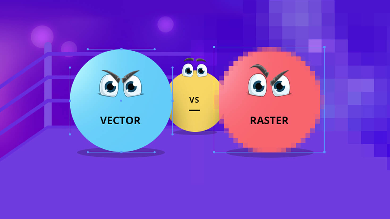
An example of the difference between vector and raster graphics
2D Design
For 2D design, I used Inkscape because it's powerful, open-source, and packed with versatile tools that make vector graphic creation easy. It allows me to create detailed illustrations, logos, and complex designs with precision, and its support for various file formats makes it compatible with other design software. The intuitive interface, combined with features like layers, nodes, and gradients, gives me full control over my projects. Plus, the community support and regular updates ensure that it stays relevant and up-to-date with the latest design trends. 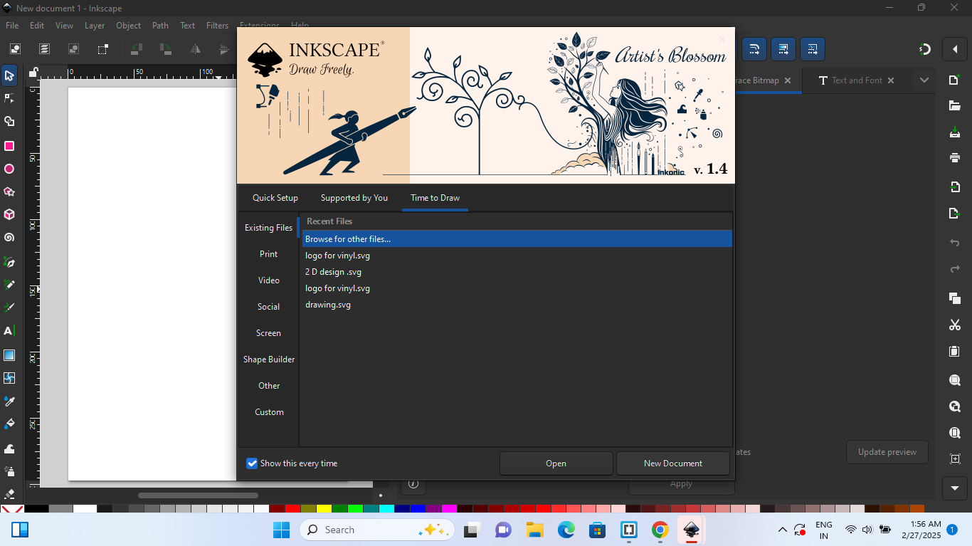 |
 |
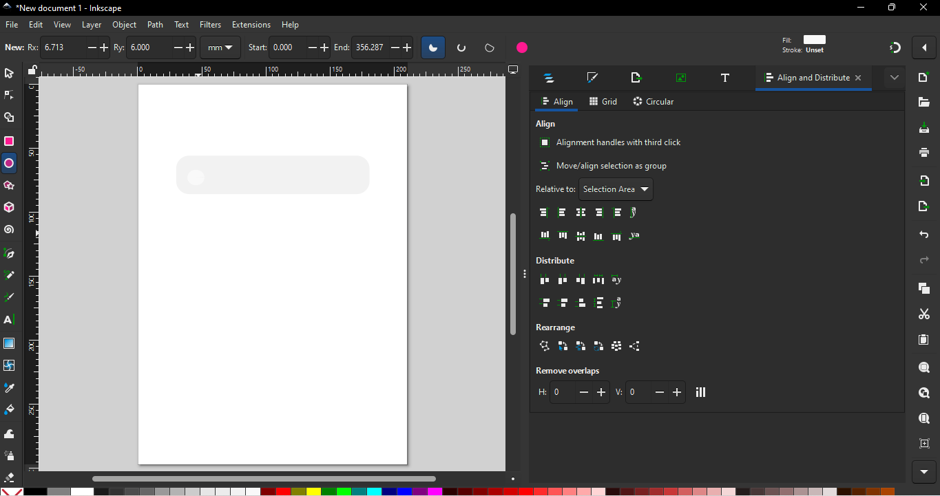
| First, I opened Inkscape and selected a new document. |
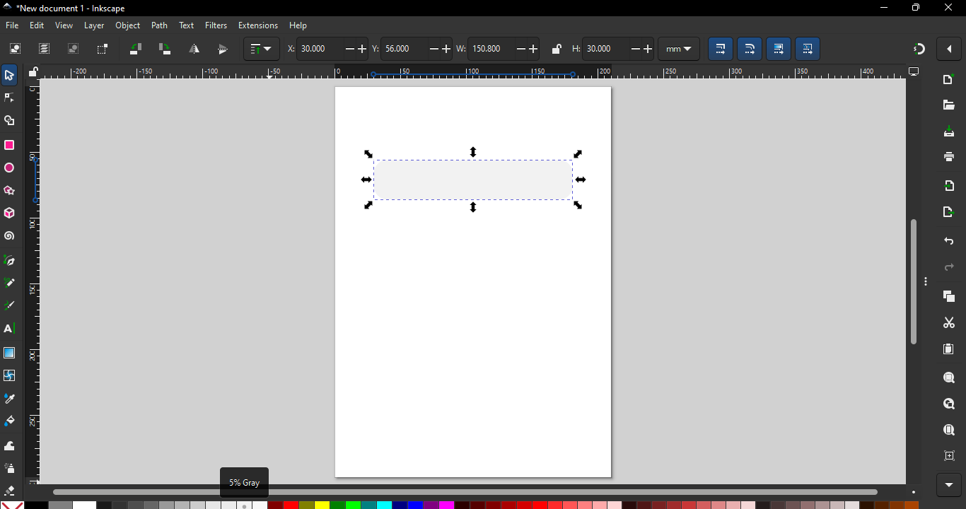
Next, I added a rectangle to the workspace. |
 |
 |
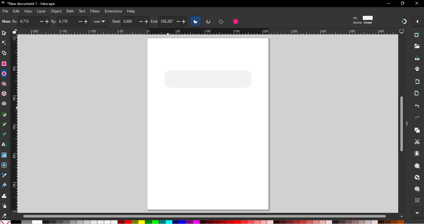
| After the rectangle, I added a circle. |
Then, I dragged and dropped the circle into the rectangle. |
 |
 |
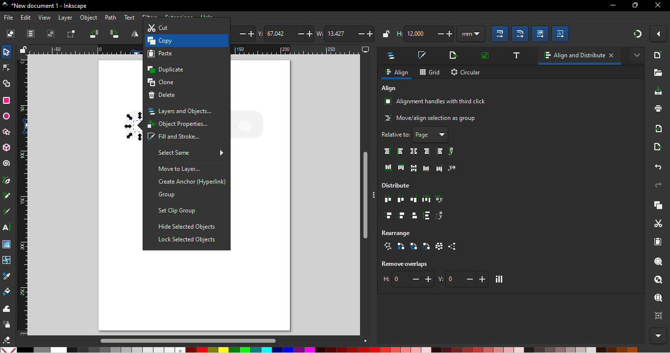
| After that, I copied the added circle and pasted it in front of the pervious circle. Using the shortcut Ctrl + Shift + A, I accessed the alignment options and centered the circle. |
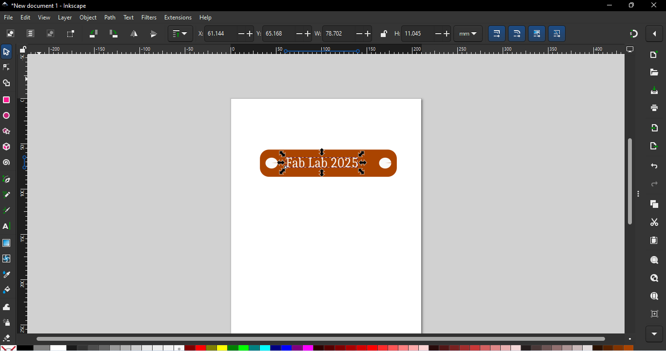
Next, I selected the text tool and wrote a name inside the rectangle. |
 |
 |
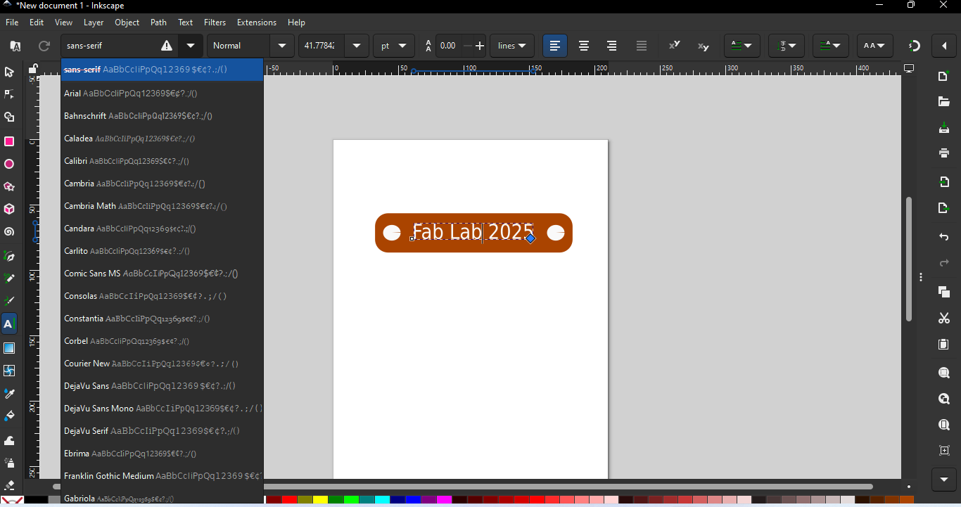
| After writing the name, I changed the font style of the text. |
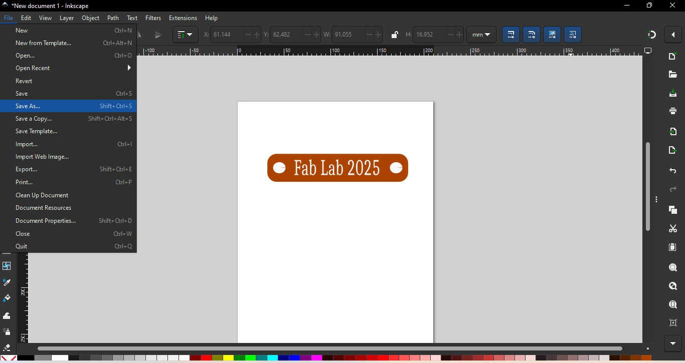
Then, to save the design, I opened the File menu and clicked on the "Save As" option. |
 |
|
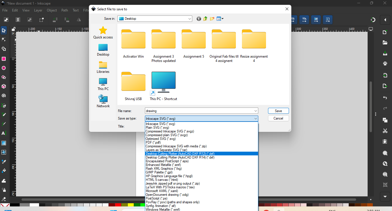
| After selecting the "Save As" option, I chose the DXF format for the file and saved it to the device |
Xn Convert For Resize Images
I used XnConvert to resize the images because it is open-source, user-friendly, and highly efficient for batch image processing. It supports a wide range of image formats and offers various editing features like resizing, cropping, and format conversion. Its simple interface and fast processing make it an excellent choice for handling multiple images quickly and effectively.
Resizeing Process
 |
|
| First visit Xn Convert offical website - "https://xnconvert.en.softonic.com" Then download it and install on your device. |
 |
|
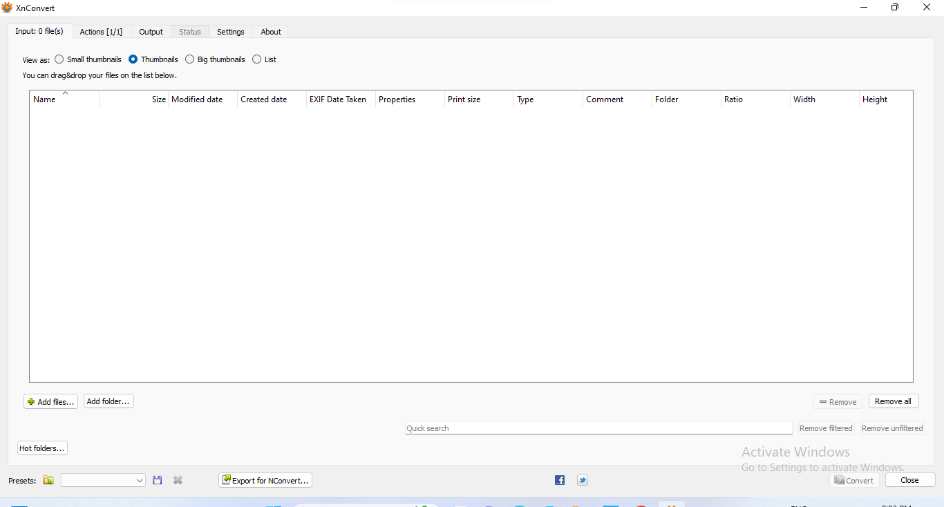
| Open Xn convert software |
 |
|
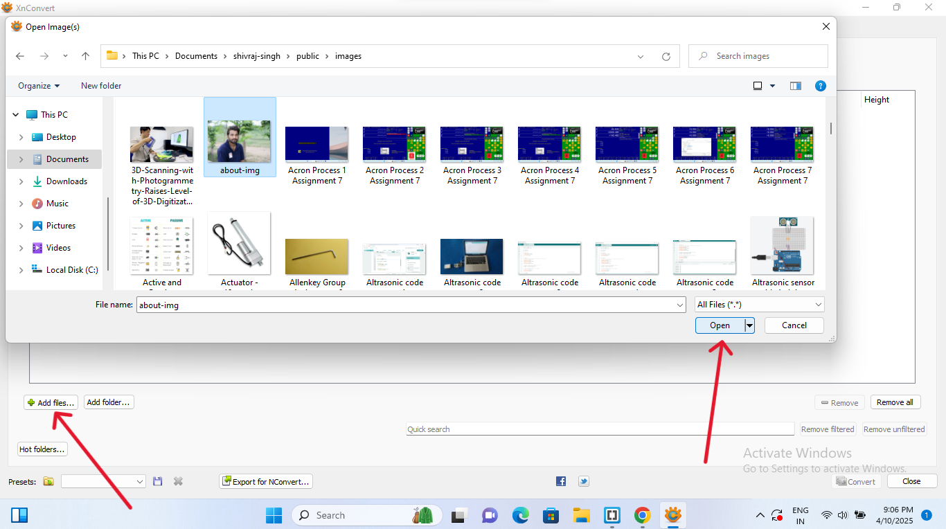
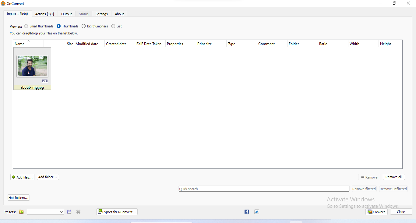
| Go to "add file" and select images & Folders from the device and press"Open" |
 |
|
| Now image is uploaded on Xn Convert |
 |
|
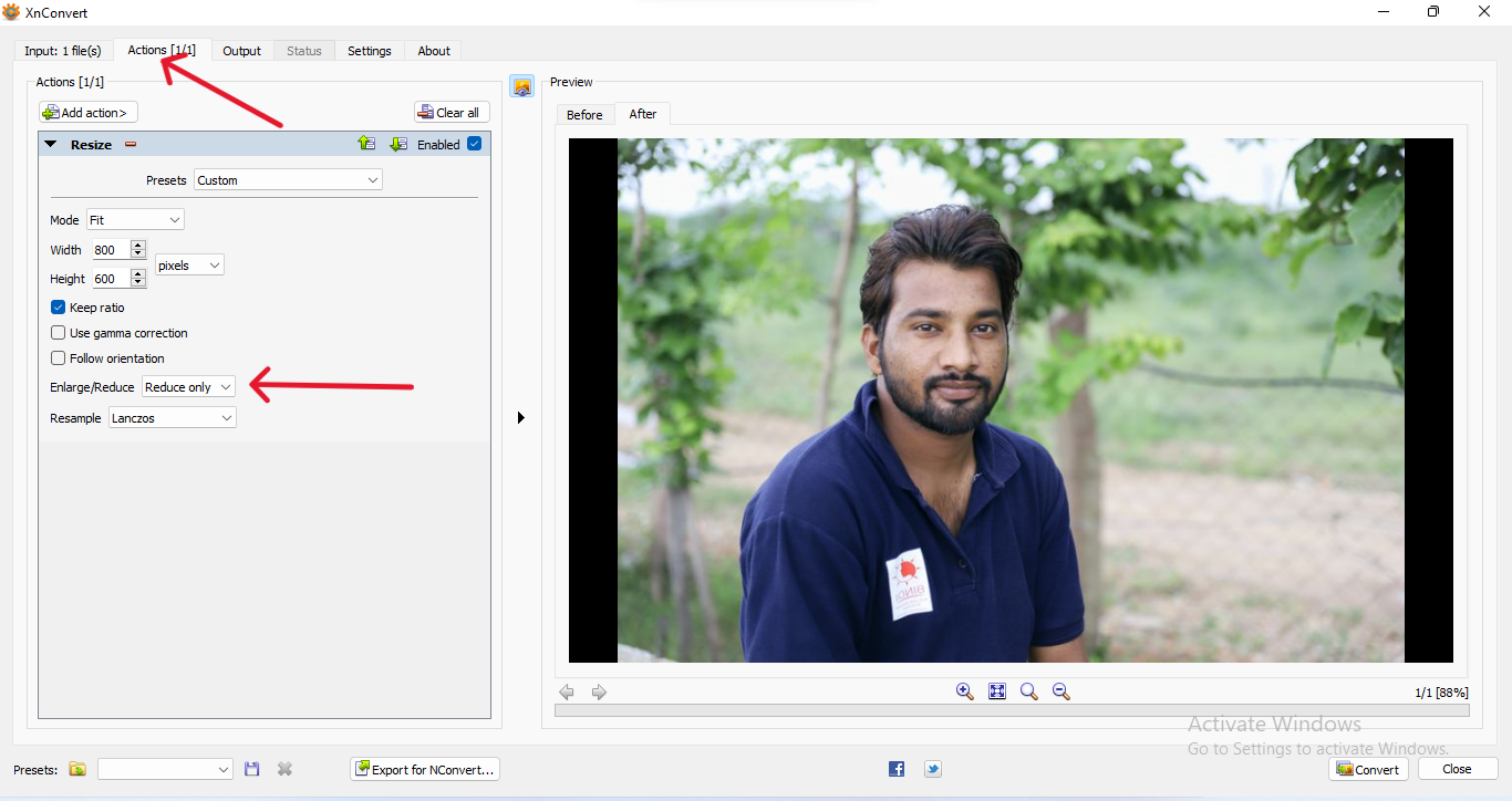
| Now click to "Add Action" and the measurement like - width,Height etc. and select "Reduse only" in background/Reduce option |
 |
|
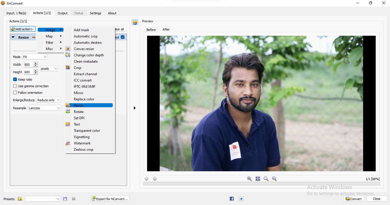
| Now again go to "add Action" and click on "Image" option and select "Resize" |
 |
|
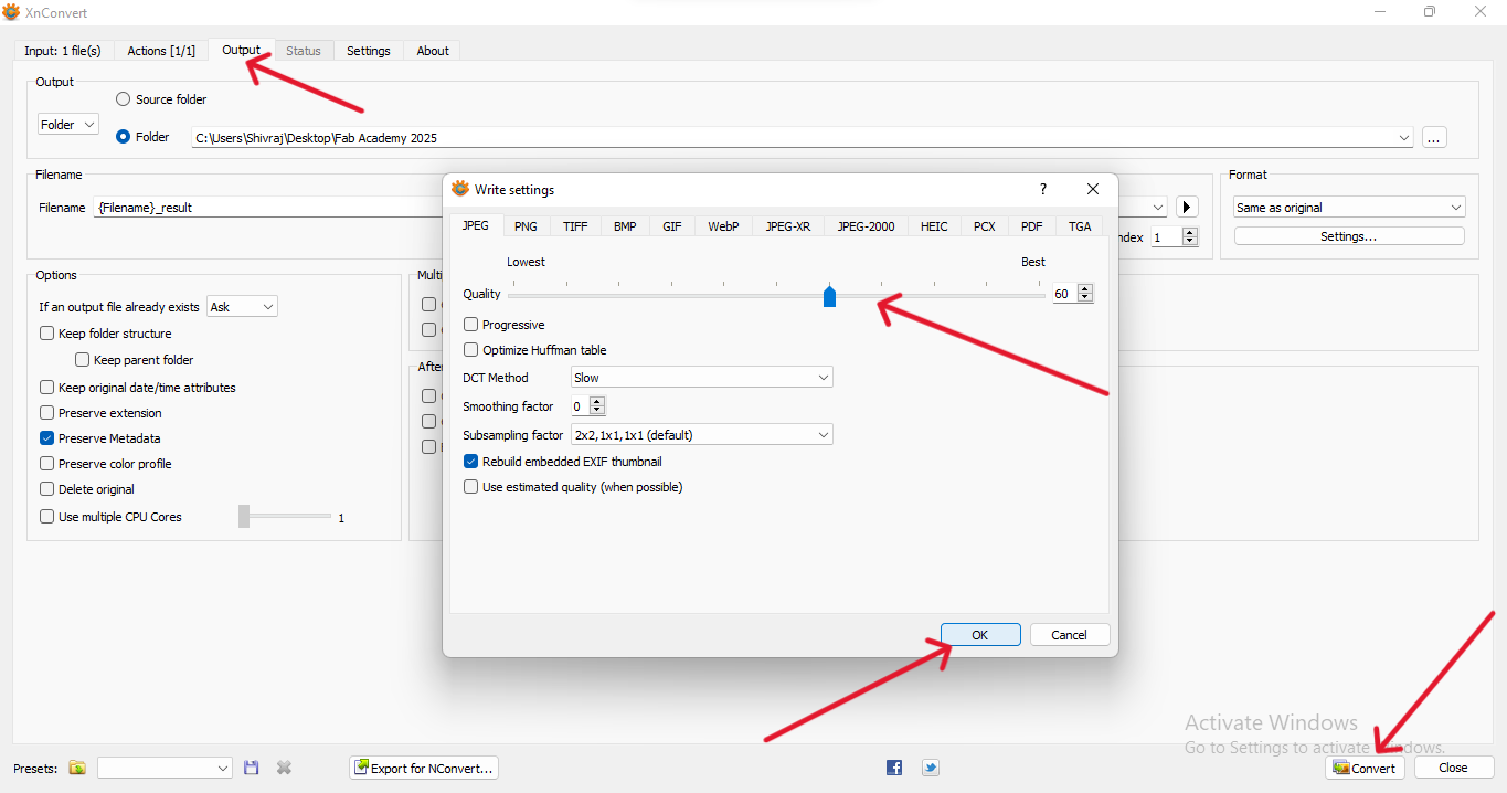
| Then go to Output - settings and adjust the quality of the image and press "Ok" then click on "Convert" |
 |
|
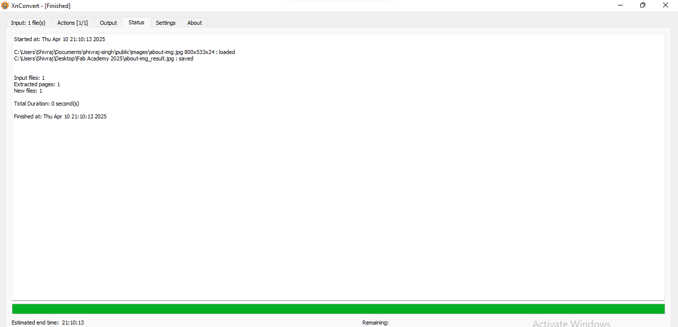
| Finally photo is resized and saved on the device. |
3D Design
For 3D design, I used SolidWorks because it specializes in parametric design, which is ideal for creating precise, detailed, and highly customizable 3D models. The parametric approach lets me easily modify designs by adjusting dimensions, automatically updating the entire model accordingly. It’s perfect for designing both simple and complex parts, assembling them into comprehensive systems, and simulating how they will function in real-world conditions. SolidWorks also offers powerful tools for stress analysis, motion simulation, and fluid dynamics, enabling me to test the performance of my designs before physical production. Additionally, its compatibility with other engineering software and the extensive library of materials and components streamline the design process. This makes SolidWorks an essential tool for creating everything from prototypes to full-scale industrial designs with a high degree of accuracy and efficiency. .png) |
.png) |
| STEP 1: First, I open SolidWorks, then click on the "Sketch" option to create a sketch. I started sktch with circle |
STEP 2: After that, I clicked on the "Smart Dimension" option in the selected sketch and started dimensioning the circle. |
.png) |
.png) |
| STEP 3: Next, I created a smaller circle inside the larger one for the hole and set its dimension. I drew a line next to the smaller circle to cut the outer part. |
STEP 4: I needed 4 circles and 4 outer cuts for my design. To do this, I clicked on the "liner sketch pattern" option and chose the second setting. Then, I entered the number 4 for circles which automatically generated 4 small circles |
.png) |
.png) |
| STEP 5: With the same process of STEP 4, I entered the number 4 for outer cut which automatically generated 4 outer cut in the design. |
STEP 6: Next, I used the Smart Dimension option to set and fix the positions of the circles and outer cuts. |
.png) |
.png) |
| STEP 7: After that, I clicked on the "Features" tab to switch the design to 3D, selected the "Extruded Boss/Base" option, and converted the design into 3D. |
STEP 8: Now, I needed a hole in the center of the design, so I clicked on "Add Sketch," drew a circle, and set its dimensions. |
.png) |
.png) |
| STEP 9: After creating the circle, I needed to make a hole in centre of the design. To do this, I selected the "Through All" option from the Features tab, which created a hole in centre of the design. |
STEP 10: After that, the design was fully completed and ready. All the necessary features, such as the circles, outer cuts, and the hole, were properly set, and the design was successfully converted into 3D. |
.png) |
| STEP 11: Measurement specifications for the final design |
Download Original File's
1. 2D design in "dxf" formet here
2. 2D design in ".svg" formet here
3D Design in SLDPRT formet here