Group assignment: Input Devices
Input Devices week, we learned:
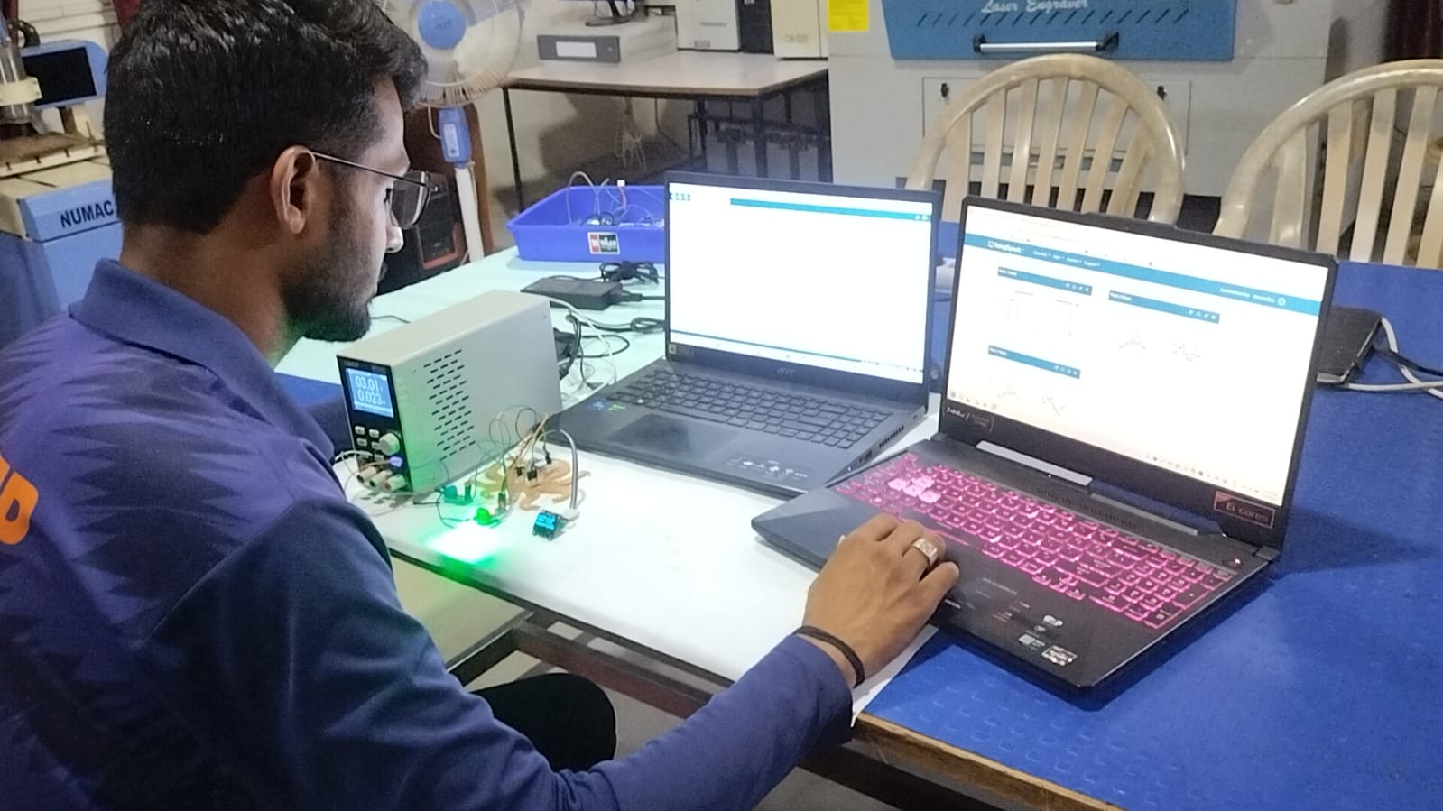
Introduction:- Using an oscilloscope and an XIAO ESP32-C3 microcontroller, digital and analog signals are investigated and analyzed. An LED is used to monitor digital signals in the experiment, and an LDR (light-dependent resistor) sensor is used to produce analog signals. These signals are shown by the oscilloscope to aid with comprehension.
LED Daigram
Hardware Components
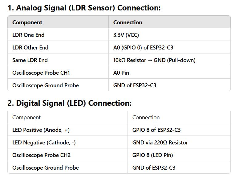
Circuit Connections
Code for programming
LED Controlled by LDR Sensor (Digital)
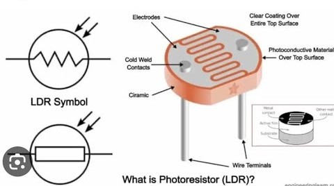
We connected the LDR to pin 2 and an LED to pin 8. When the light level drops (i.e., it's dark), the LED turns on. When it's bright, the LED stays off.
#define LDR_PIN 0

void setup() {
  Serial.begin(115200);
}

void loop() {
  int ldrValue = analogRead(LDR_PIN);
  Serial.println(ldrValue);
  delay(500);
}
LED Controlled by LDR Sensor (Analog)
In this version, we used analog pin A1 to read LDR values. When the sensor detects darkness (value below 500), the LED on pin 8 turns on.
#define LDR_PIN 0
#define LED_PIN 8

void setup() {
  pinMode(LED_PIN, OUTPUT);
  Serial.begin(115200);
}

void loop() {
  int ldrValue = analogRead(LDR_PIN);
  Serial.println(ldrValue);

  if (ldrValue < 500) {
    digitalWrite(LED_PIN, HIGH);
  } else {
    digitalWrite(LED_PIN, LOW);
  }

  delay(500);
}
Single of the sensor in oscilloscopeg
| Digital Signal With oscilloscope | Analog signal With oscilloscope |
Oscilloscope Observations
Digital Signal (LED Blinking):
- LED On State: The signal reached a high level of approximately 3.3V when the LED was on.
- LED Off State: The signal dropped to 0V when the LED was off.
- Oscilloscope Output: The oscilloscope displayed a square wave, where the signal alternated between high (3.3V) and low (0V) levels. This change occurred as the LED toggled between on and off states, based on input from the LDR sensor.
Analog Signal (LDR Sensor):
- Bright Light Condition: The voltage reading increased, approaching 3.3V as the LDR detected a significant amount of light.
- Dark Condition: The voltage decreased to nearly 0V when the LDR was exposed to minimal or no light.
- Oscilloscope Output: The waveform shown on the oscilloscope displayed smooth, continuous changes as the light intensity varied. Unlike the digital signal, this signal fluctuated gradually, depending on the ambient light level.
Conclusion
The oscilloscope's CH1 successfully displayed the LDR's analog signal, which fluctuated continuously based on light intensity. The LED's digital signal appeared as a square wave, alternating between HIGH (3.3V) and LOW (0V).
By evaluating the circuit and software implementation, the oscilloscope helped confirm the behavior of the real-time signals.