.gif)
Assignments
Group Assignments
- Do your lab's safety training test runout, alignment, fixturing, speeds, feeds, materials, and toolpaths for your machine
Individual Assignment
- make (design+mill+assemble) something big (~meter-scale) extra credit: don't use fasteners or glue
extra credit: include curved surfaces
GROUP ASSIGNMENT
More specific detailed from the worked done with Ernesto Castro in Fab Lab Universidad de Lima here
Fab Lab Ulima s a f e t y t r a i n i n g

3000 series Multicam Router CNC.
The machine we have at Fab lab Ulima is the 3000 series Multicam Router CNC for an area of 2040mmx1200mm. I hve never used this machine. The instructor and the machine worker give me the first steps and security steps to start. First I was gave a lab coat, safety earmuffs, gloves, glasses and I had to wear safety shoes with steel tip, and I use my construction boots that has them.
To start the machine I had to identify its parts. Where to turn on, the air suction, where are the mills and where is the command control.
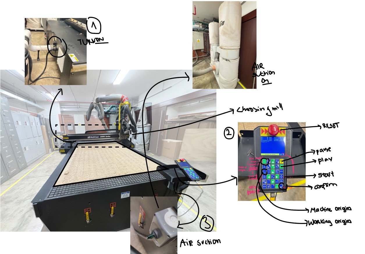
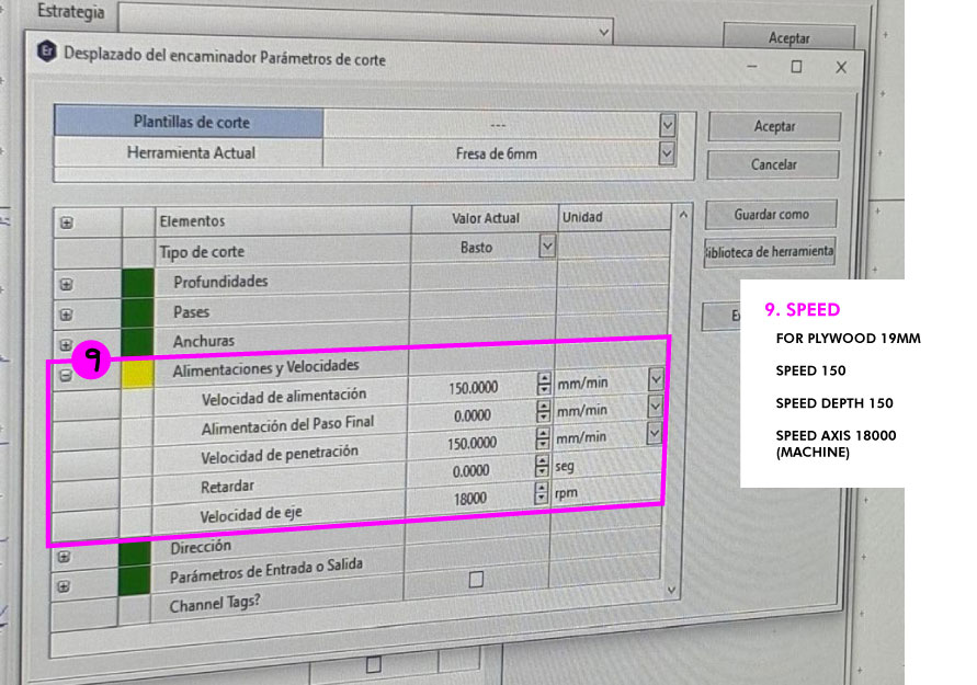
The machine works with EnROute Software Where to select the mill, passes and cuts for the machine.

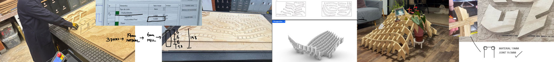
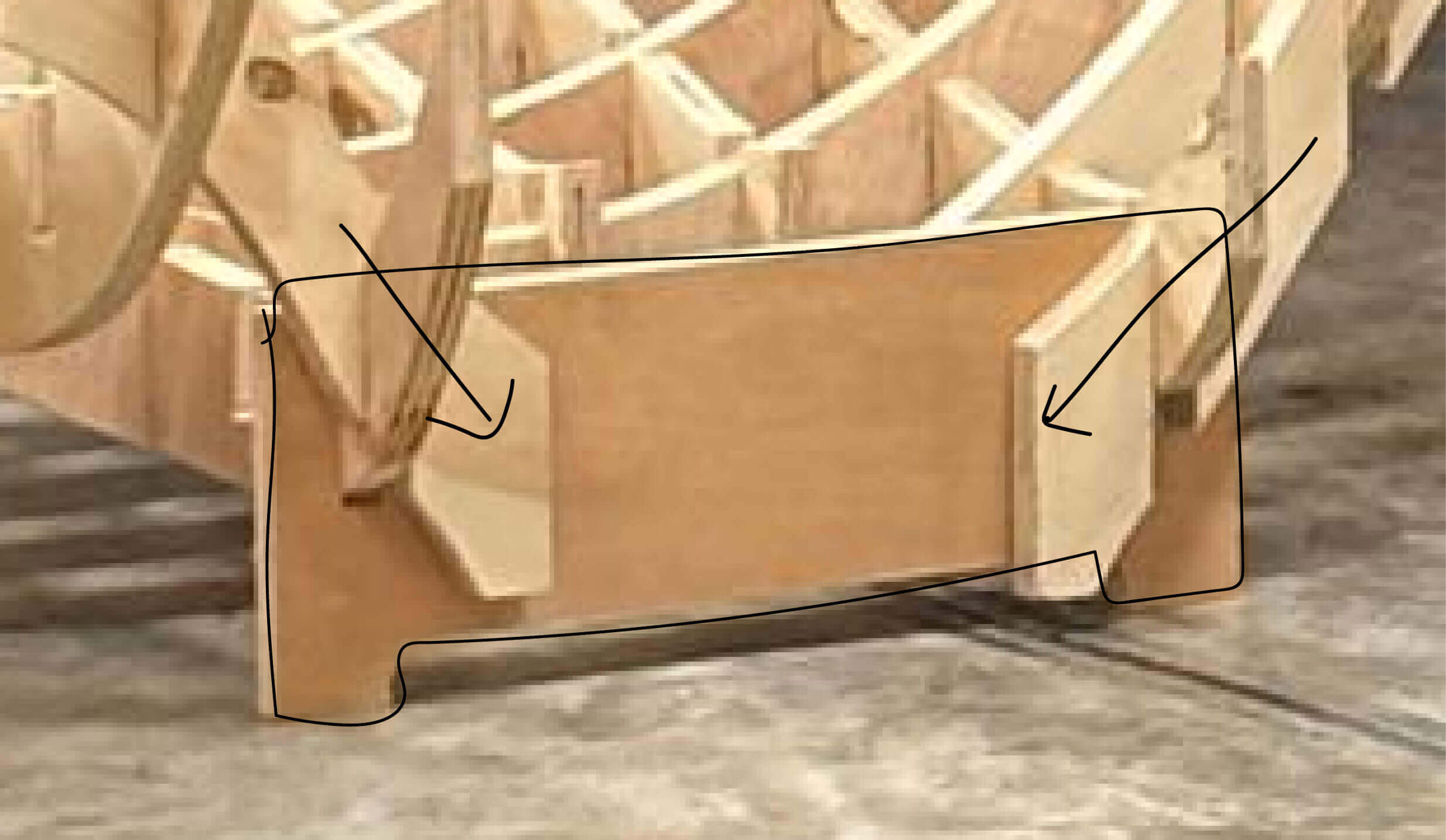
Tests t o l e r a n c e s and dog-bones tangents
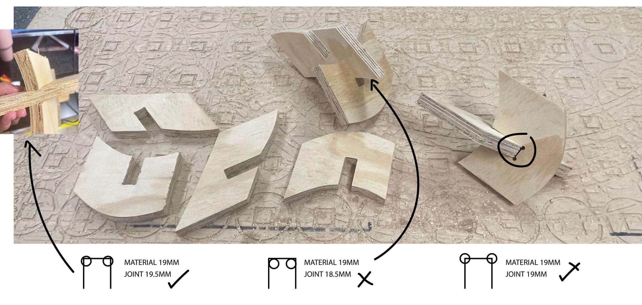
My part of the group testing was to test tolerances. I did some joitns for my individual proyct, also texting how it cuts curves. I tried to make some dog bones different by the tangent of the 6.2mm circle for the mill of 6mm. The best one was the 19.5mm for plywood of 19mm. It was safe to joint and not forced. So I choose to make my individual project in this material.
S P O I L E R a l e r t
Plywood of 19mm is TOO HEAVY. Everything connected, however with two pieces it starts to be so heavy and the joints are so precise that it involves applying force to some parts to fit them together. It also involves twisting the entire structure to secure it at the bottom and then at the top.
INDIVIDUAL ASSIGNMENT
For the "make something big" assignment I wanted to do furniture. As an architect I have always liked when furniture is a piece of statement in a space. And that is why I thought about the coffe table in my living room. How can I incorporate the love for nature of both my mom and I with a piece that focus the living room?. It was the perfect idea! And also to experiment with parametric design and joints to maybe have different versions of the idea.
nature coffee t a b l e
F i r s t I D e a
sketches
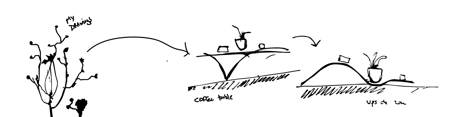
Following the drawings in my cyanotypes I wanted to make a coffe table that came from nature curves of a tree and focus on the plants pots. Also I didnt want the typical 4 points of support in the ground. And I wanted the typical table to be like levitating.
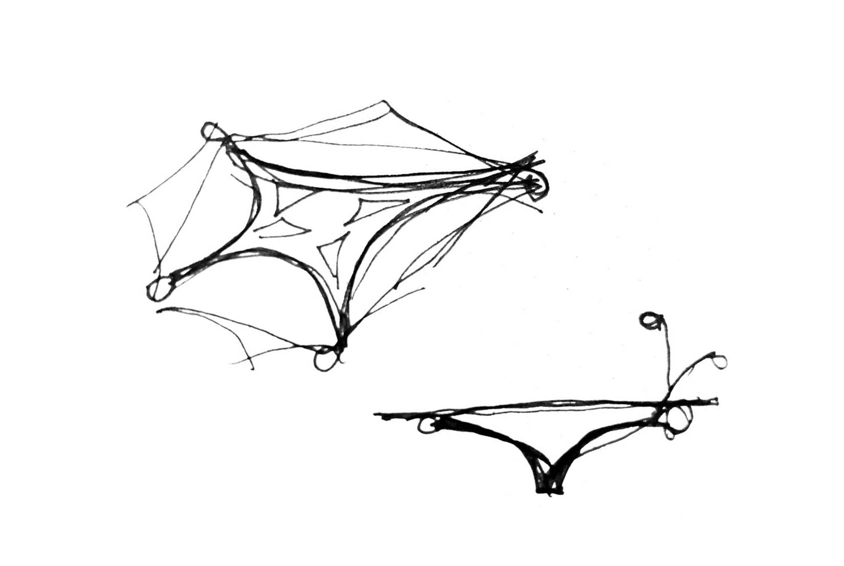
Initial sketch of the table in plan and elevation.
Parametric design
I made some first curves in Rhinoceros as I wanted the limits of the table to look like. I draw this lines first in parallel view in front, top, rigt, left and back view. So I could control each view of the table.
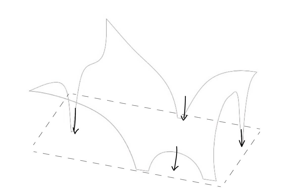
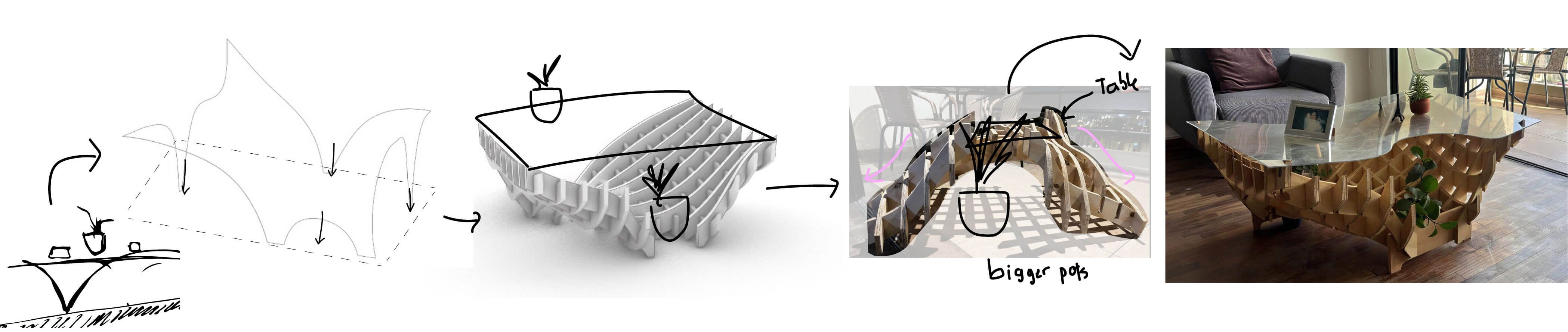
I did not wanted the supports of the table to be in each corner as it could be in every table. I first did the elvation curves I imagine for each side and the loft the curves in rhino to see the natural curve of each elevation while joining in one polysurface.
The volume left by the loft the curves in rhino.
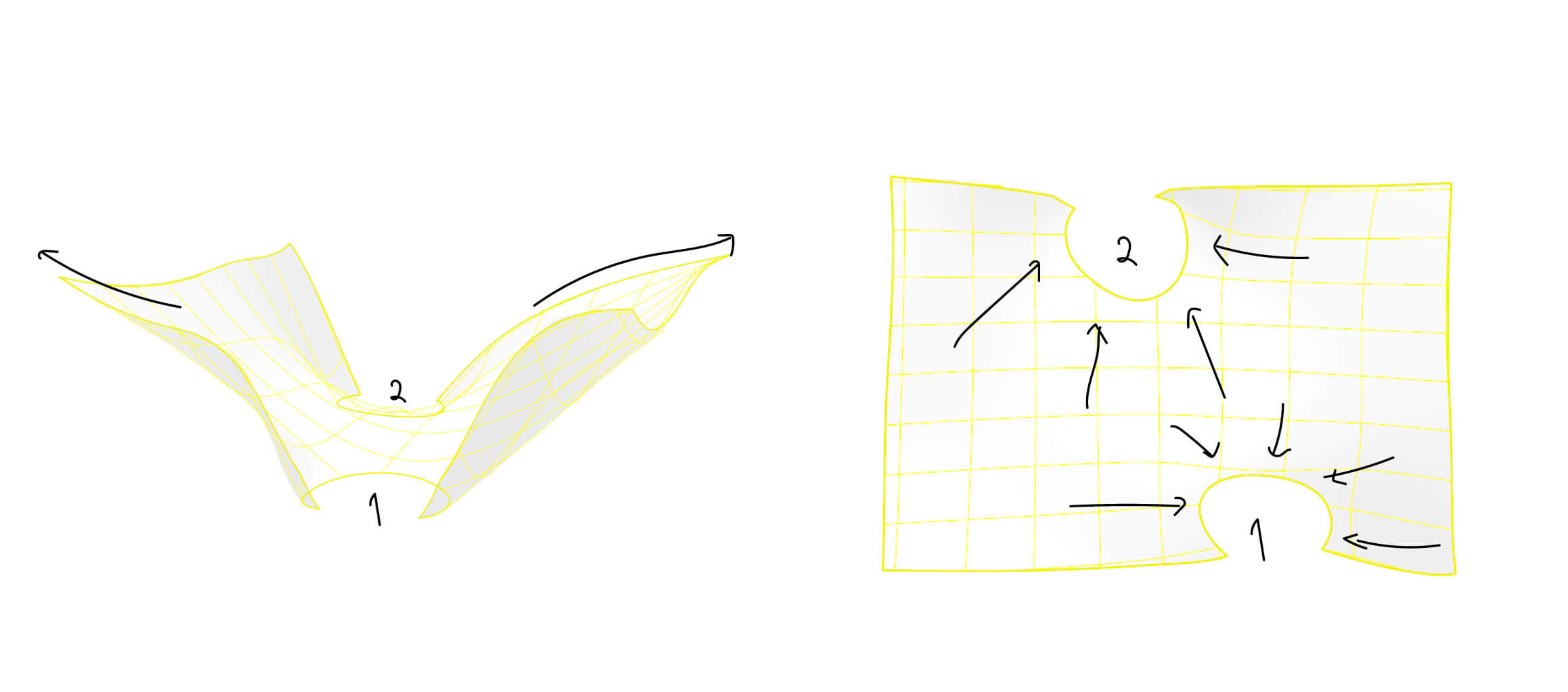
I liked how the loft made a natural 2 supports for the whole table. The challenge was to center the weight in just this 2 supports. So to think about the the structure I choose a waffle structure in grasshopper because I can manage this weigh easier. I made it with bowerbird plugin I download from here. I used grasshopper to make the structure and not itself in Rhino to have the option of changing the joints space and material thickness.
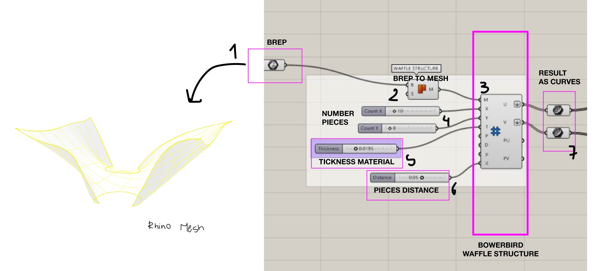
Bowerbird waffle structure process
Why Waffle structure?
To avoid extra joints and make each piece itself to be the joint. Also, to play with the dimensions of the acrylic or glass table and the placement of the flowerpots, since if there are also flowerpots at the base, the upper base of the acrylic could open up to them, leaving a gap so they naturally extend over the table.
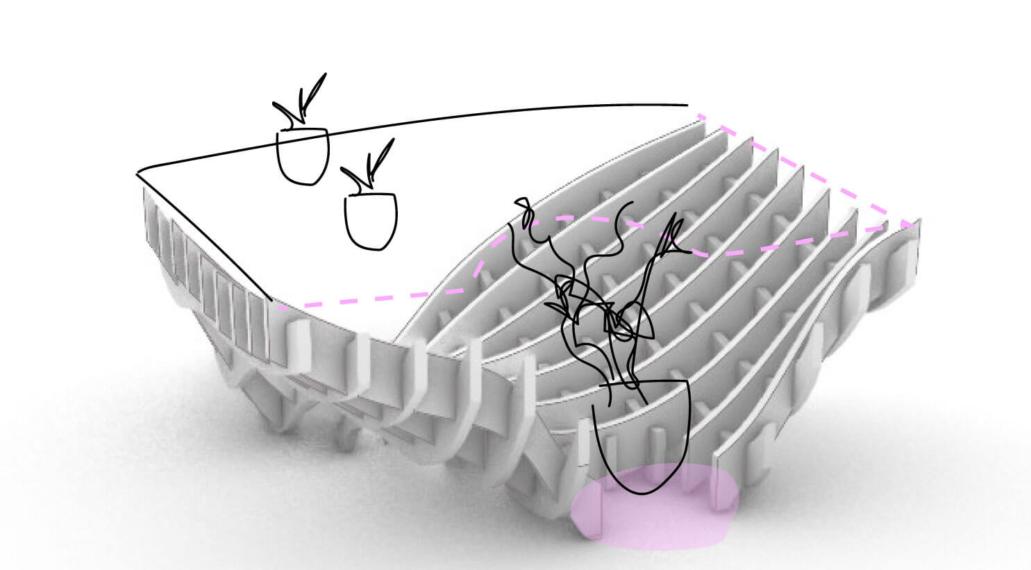
Result idea after the bowerbird organization of the pieces and joints.
To organise the pieces and find the correct order to set everything up I did the nesting in grasshopper in an area of 2.40 x 1.20 m that is the area of the plywood. I used OPEN NEST plugin in Grasshopper to help me organice the alredy pieces I had. For this I worked with the result curves and projected them in order to then organice in a sheet size of the material I mentioned. After that with each center project text in each piece.
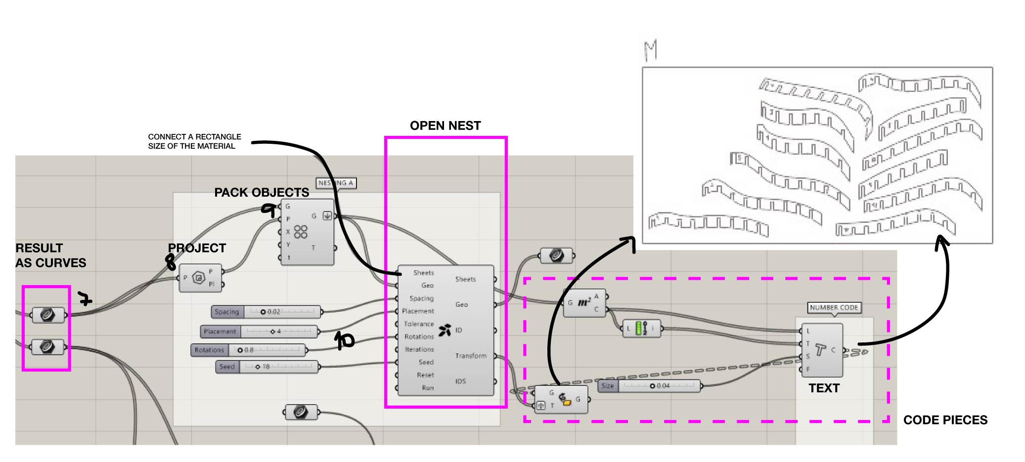
Nesting process
How to make the dog bones
To make the dogbones in the nesting I tried importing it in Fusion, however I couldn't make it there I think because of the lots of curves of the forms. However I found a way to make the dog bones in rhino with a phyton script I download from a rhino forum here. I also found a rhino plugin that makes the same but i cound't make it work. It is listed here.
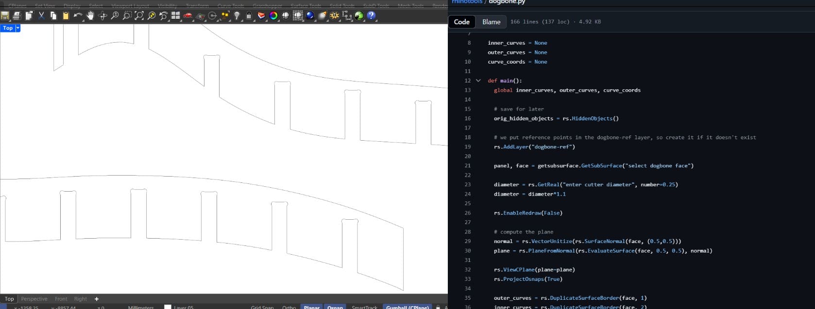
Dog bone script in rhino
From recommendation of my instructors I gave a diameter of 6.2mm for a 6mm mill since it has to have a minimun tolerance. Also de joints for 19mm plywood are made with 19.5mm as in the group test it fit perfectly with not much pressure.
f a b r i c a t i o n P r o c e s s
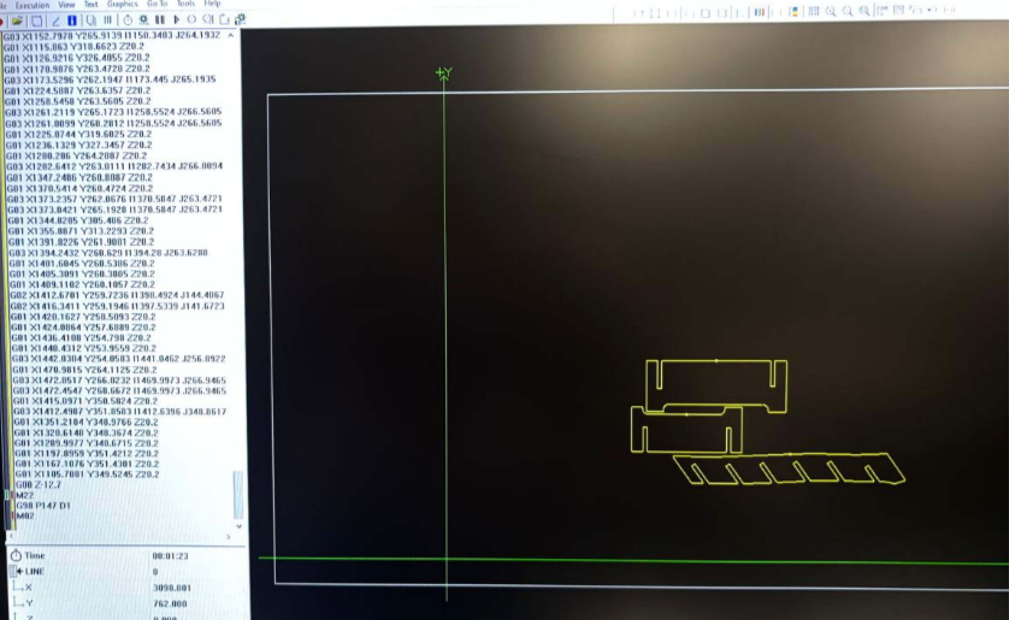
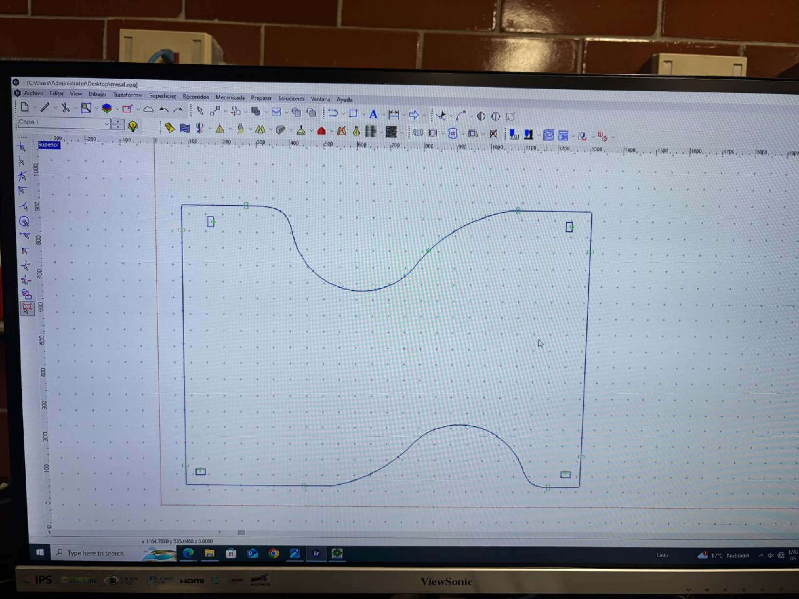
Routing the g code for fabrication
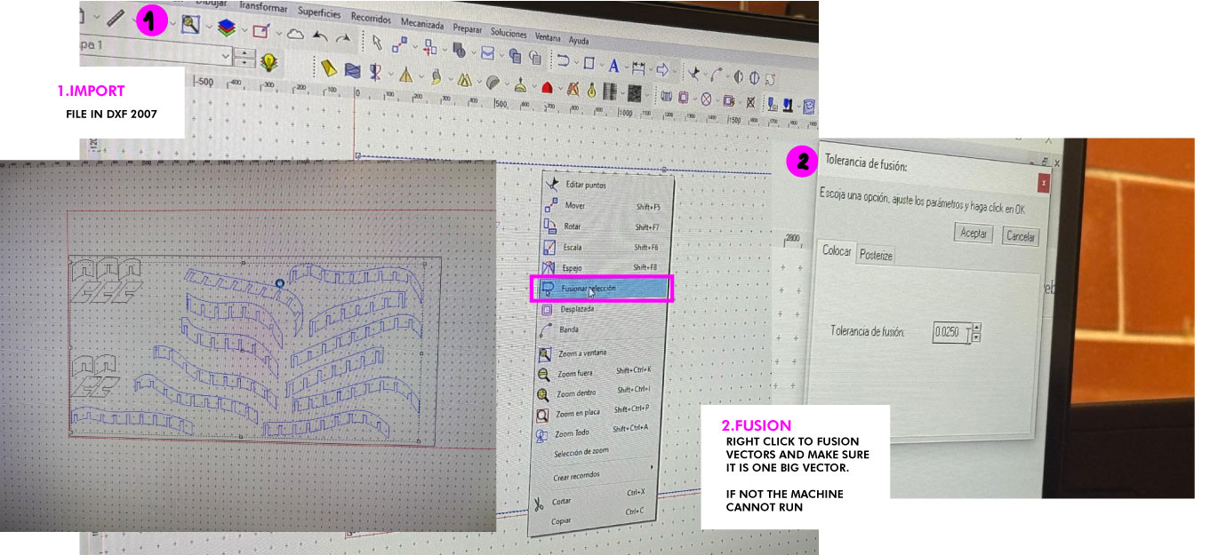
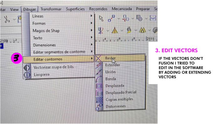
The manufacturing process began with the generation of the G-code in the CNC software, ensuring that all lines were consistent and there were no gaps.
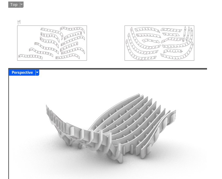
NESTING result ready for fabrication.
The nesting result in grasshopper organized the pieces in the size of the material and machine. This file was exported in .dxf to EnROute Software:
place components
connect components
name and connect components
name and connect components
name and connect components
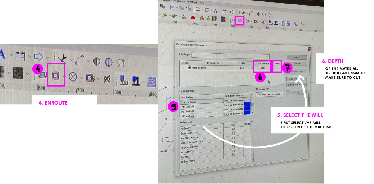
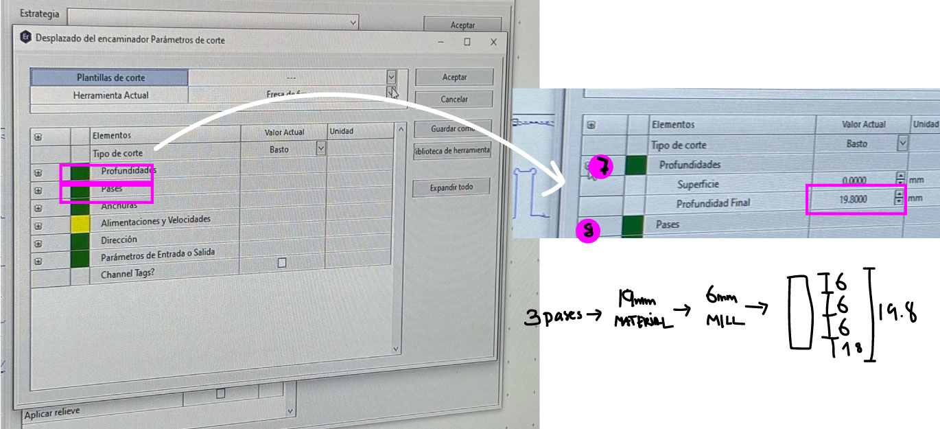
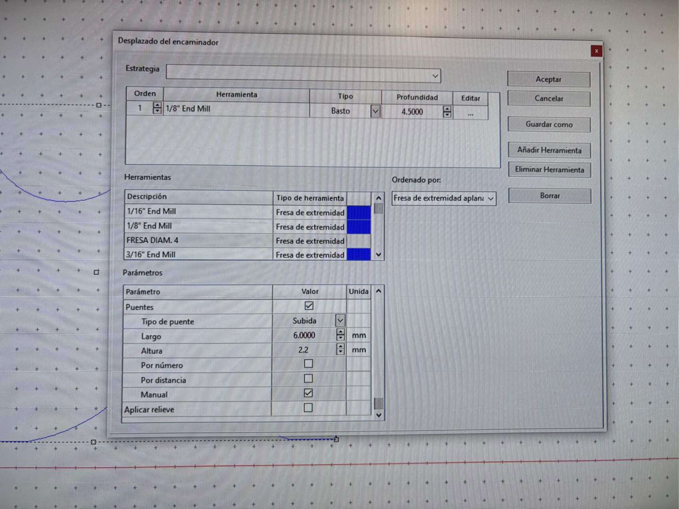
Setting EnRoute.
Cutting the pieces in the CNC machine
First, I had to change the mill and set the origin in XY and Z.
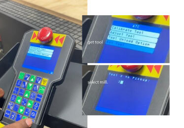
Select the mill
Changing mill
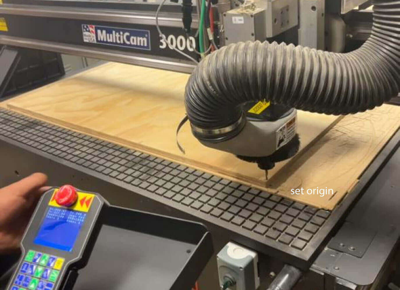
Set the origin XY
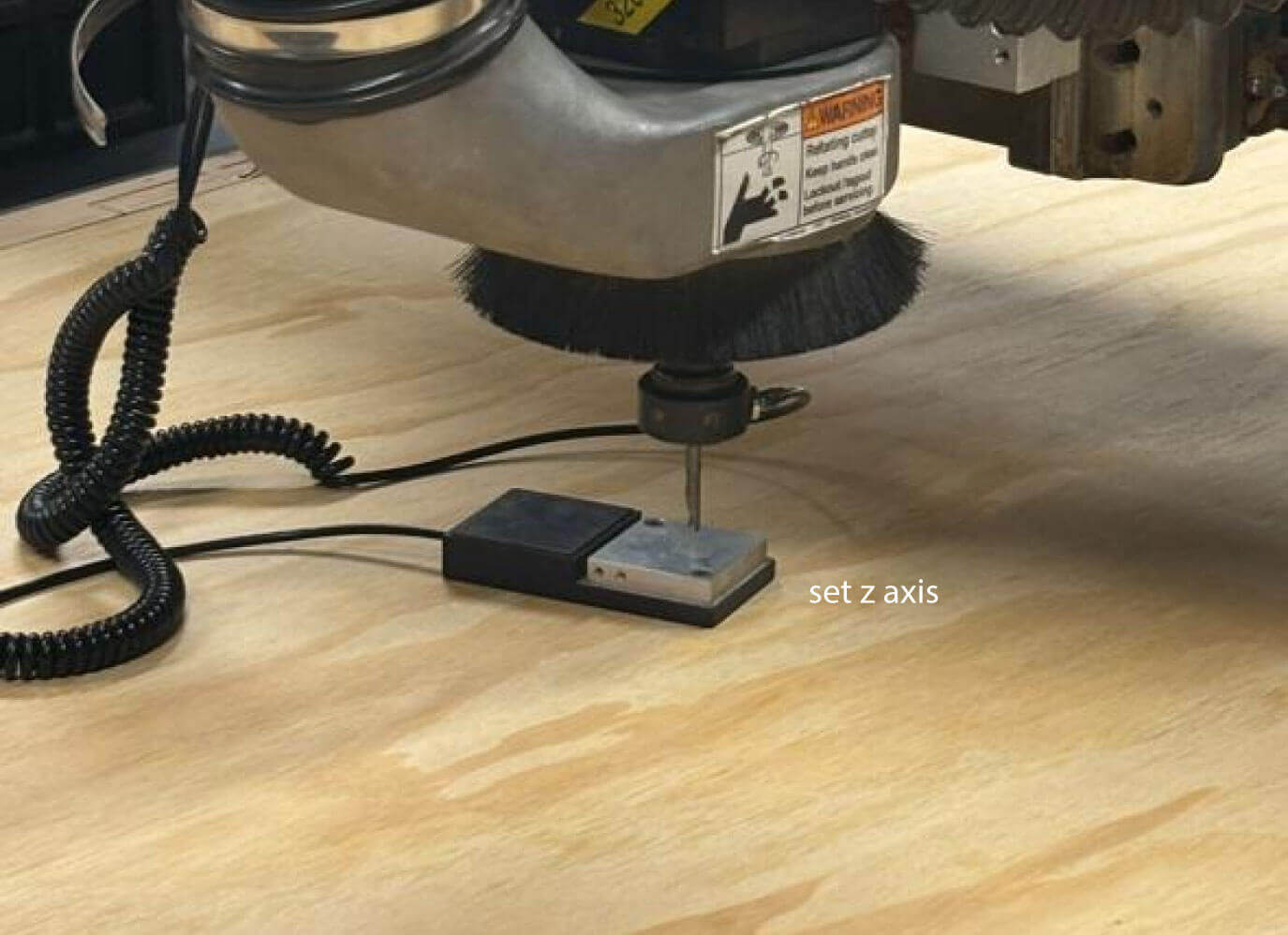
Set the Z axis
Then I send the gcode to the machine and waited around an hour.
G code in cutting process
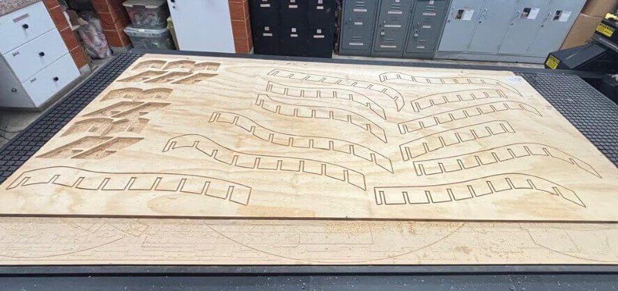
Pieces cut result
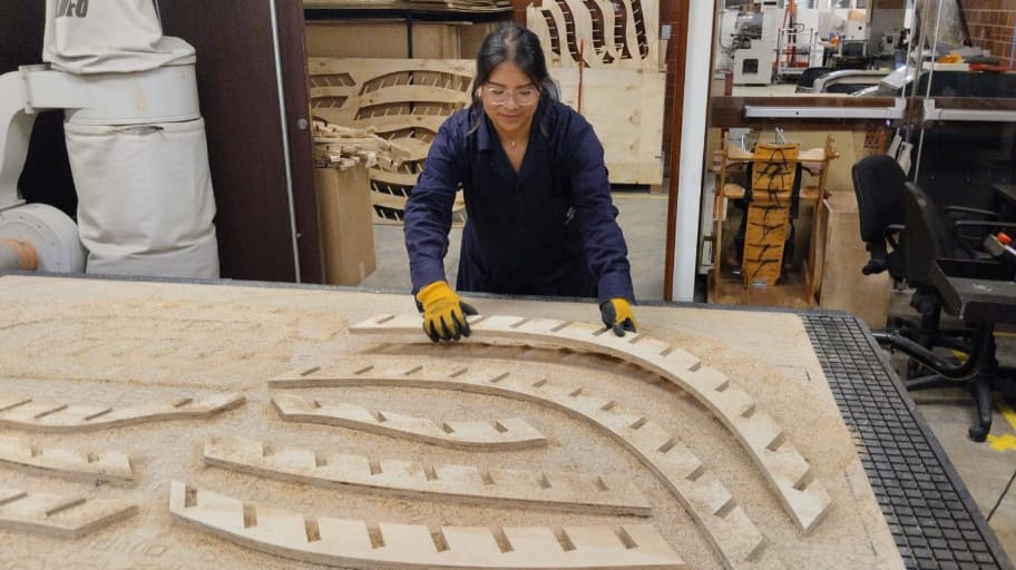
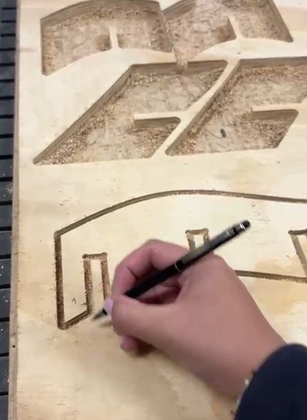
Taking out the pieces
I had to be very careful taking out the pieces and marking with letters and numers which piece each of it are. I messed some pieces and had to cut them again. ⬇️⬇️⬇️
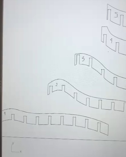
Number code in Rhino
assembly process
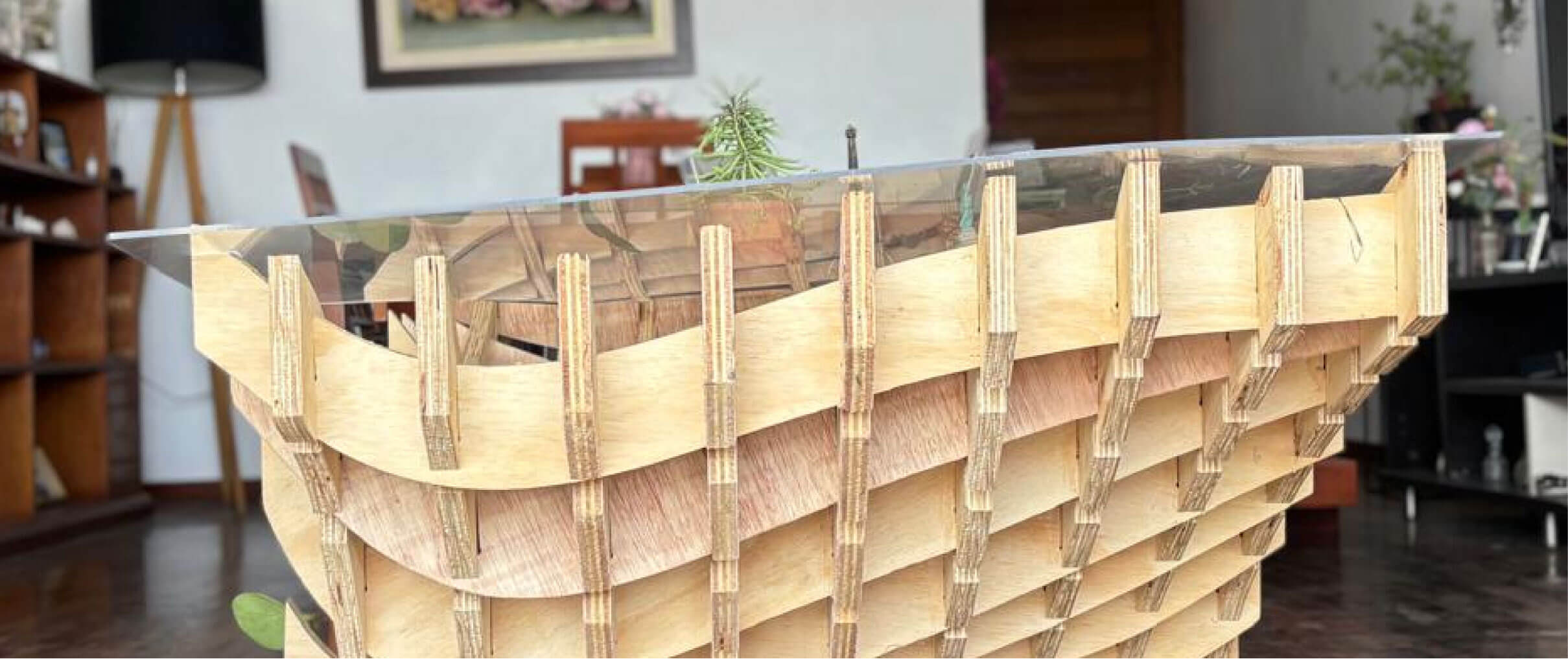
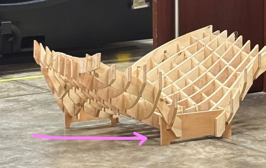
T e s t 1: t h e S T R U C T u r e
The first assembly attempt was at my house, on the terrace, as you can see in the video. When coding the pieces, I tried to follow the Rhino model and the codes, but I couldn't fit all the joints on my own. The table finally came together, but it was very weak and kept falling over due to gravity🥲.
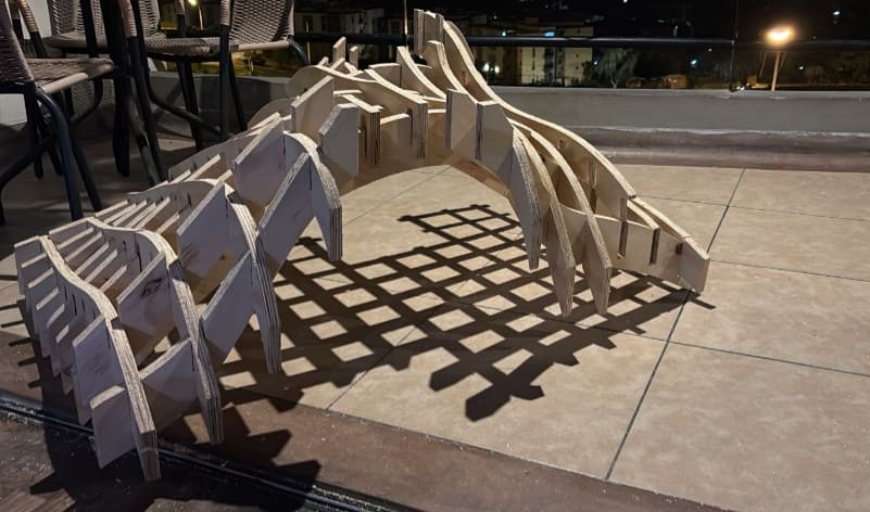
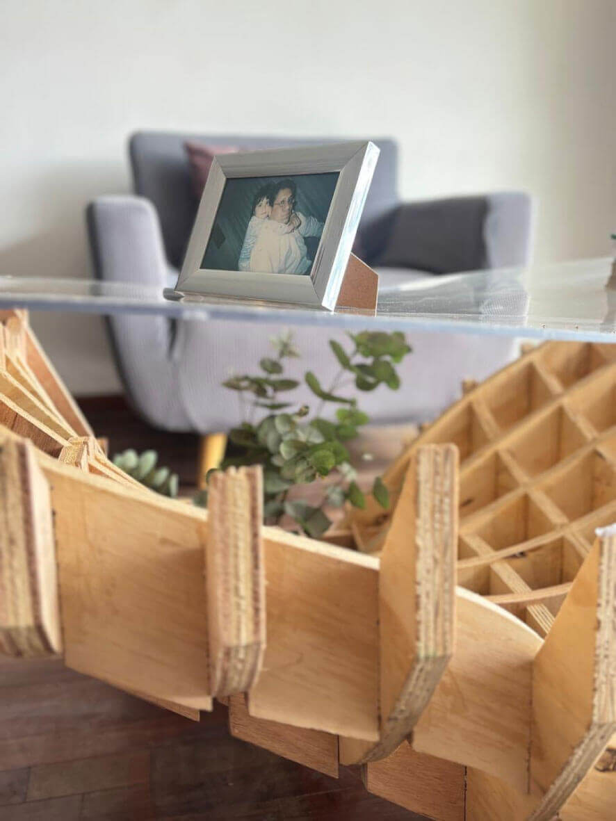
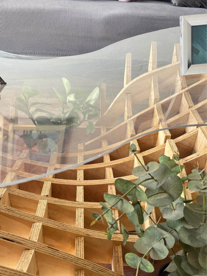
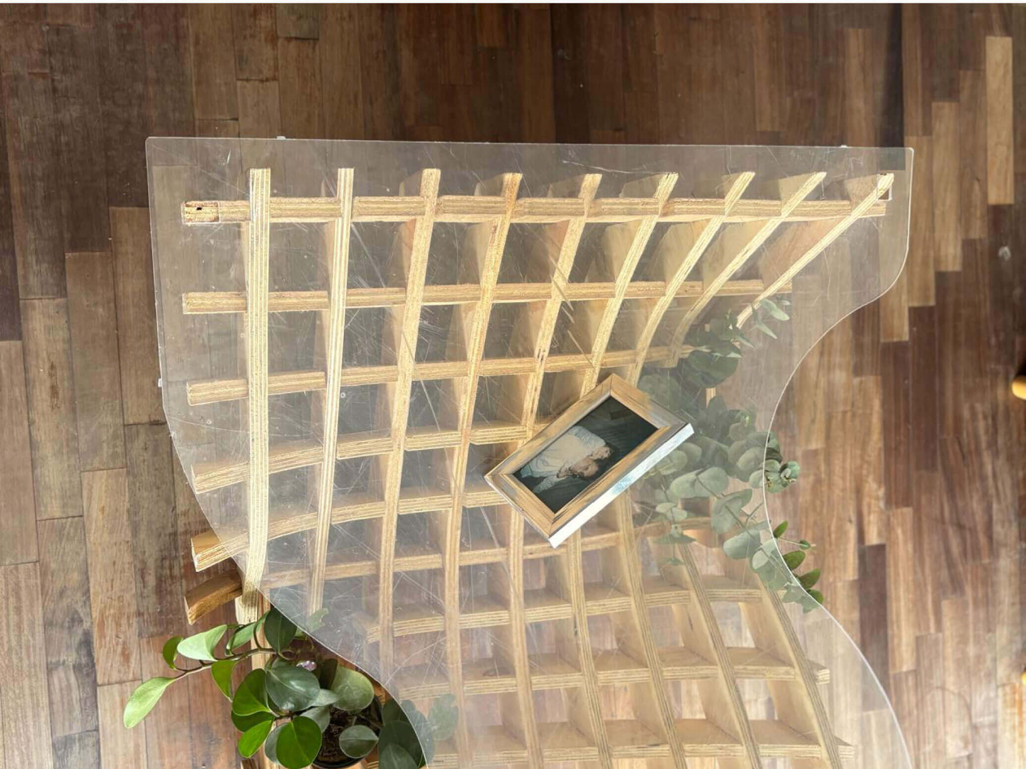
structure upside down
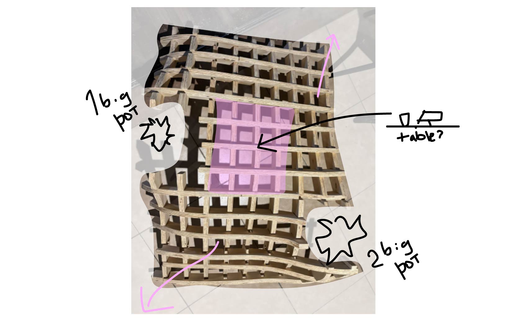
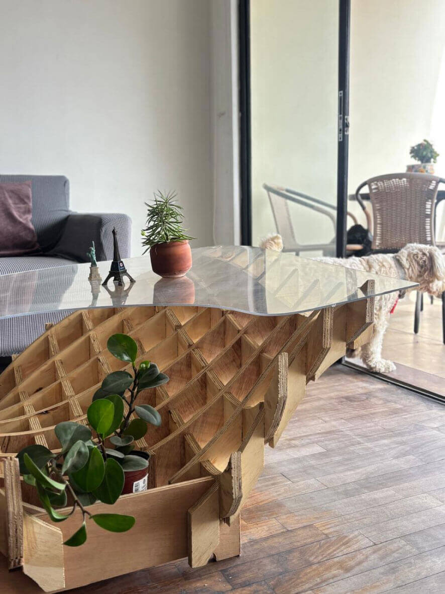
top view and plants positioning
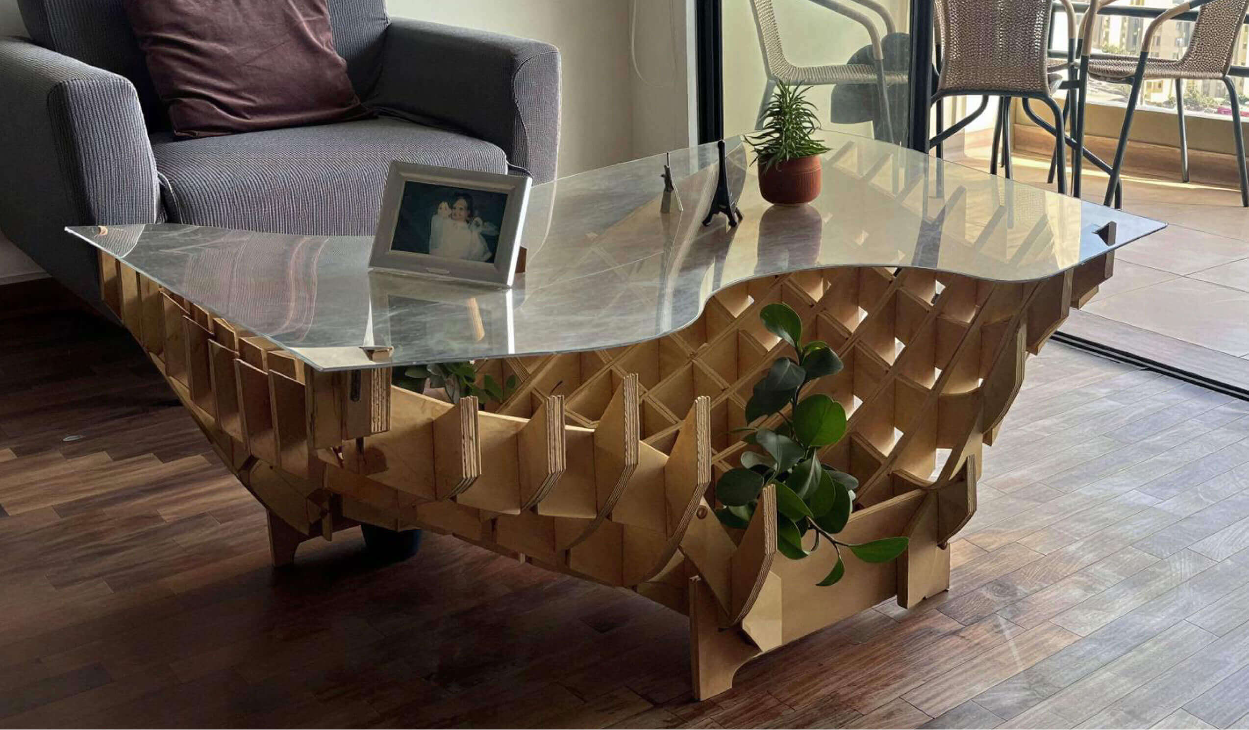
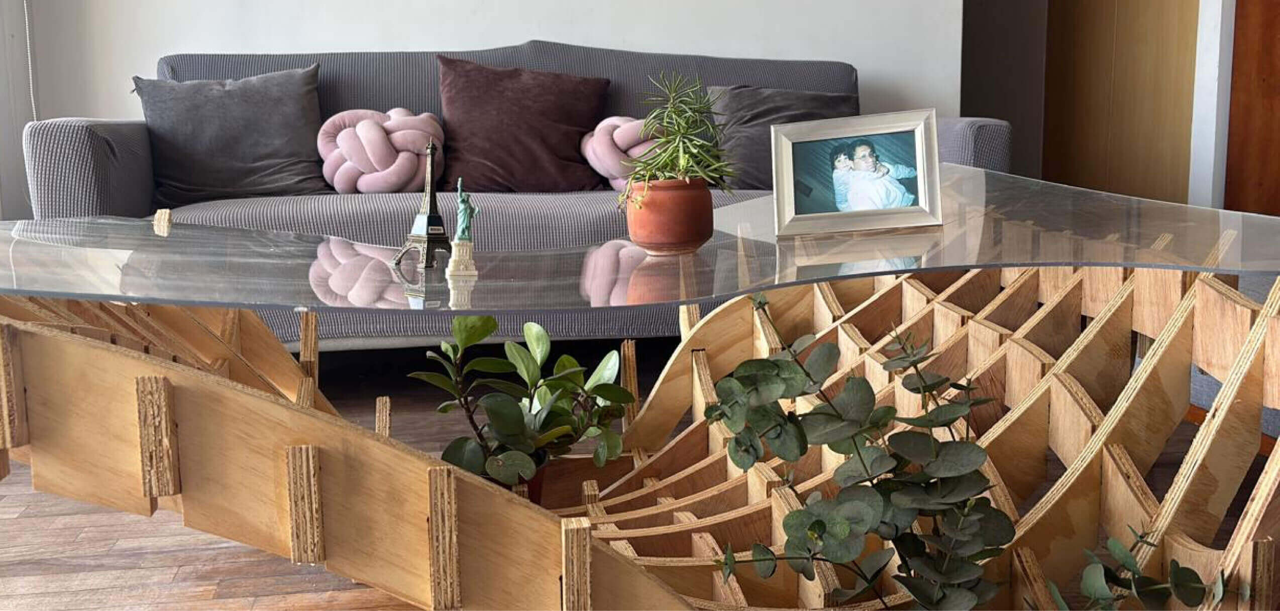
Still make it to work as a table in my living room.
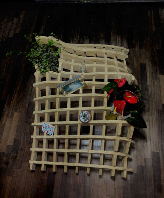
Table in my living room
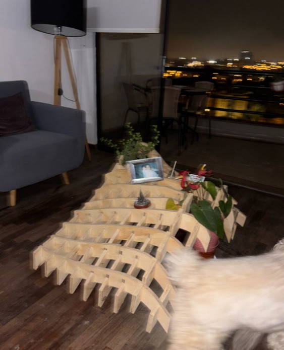
Table in my living room
Test 1 : Structure result
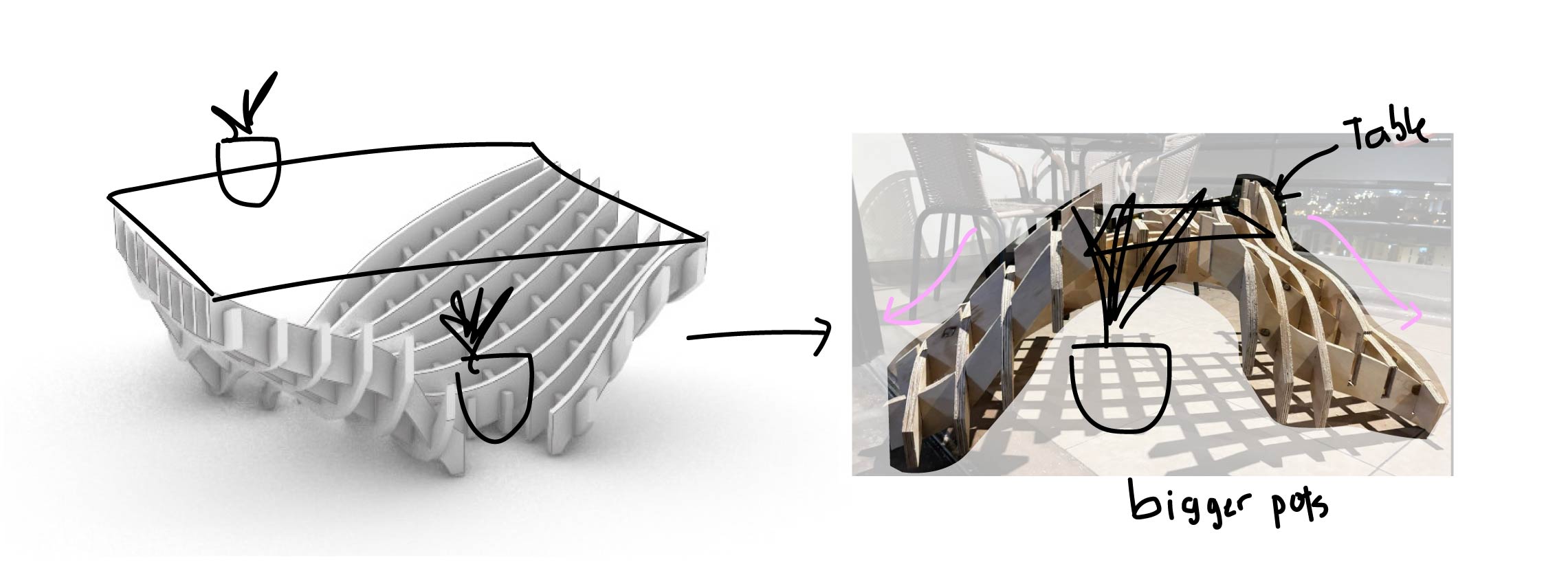
Original form and change while making
From the idea to the result it is upside down. The initial idea was that only the two edges would support the acrylic as a conventional table but an organic base. However, the supports where not doing their job and could not stabilize the table. The weight in one side make it imposible to stand.
What's next?
I still need to find a way to make it work the original way. I want to mix acrylic in large scale to see how it cuts with the Mlticam CNC. And how I can make it feel like one of my drawings.
Some suggestions to solve the problem of gravity and weight of the material:
- I should have not made the joint too deep.
- I can make a base support and elevate all the project in order to make a more stable support.
- The acrilic can help with the balance of the table if I made some layers in the weakest points. This can also help me determine which areas the flowerpots will go in.
T e s t 2: S U p p o r t s a n d A c r y l i c T A B l e
New pieces for support
Taking out the pieces
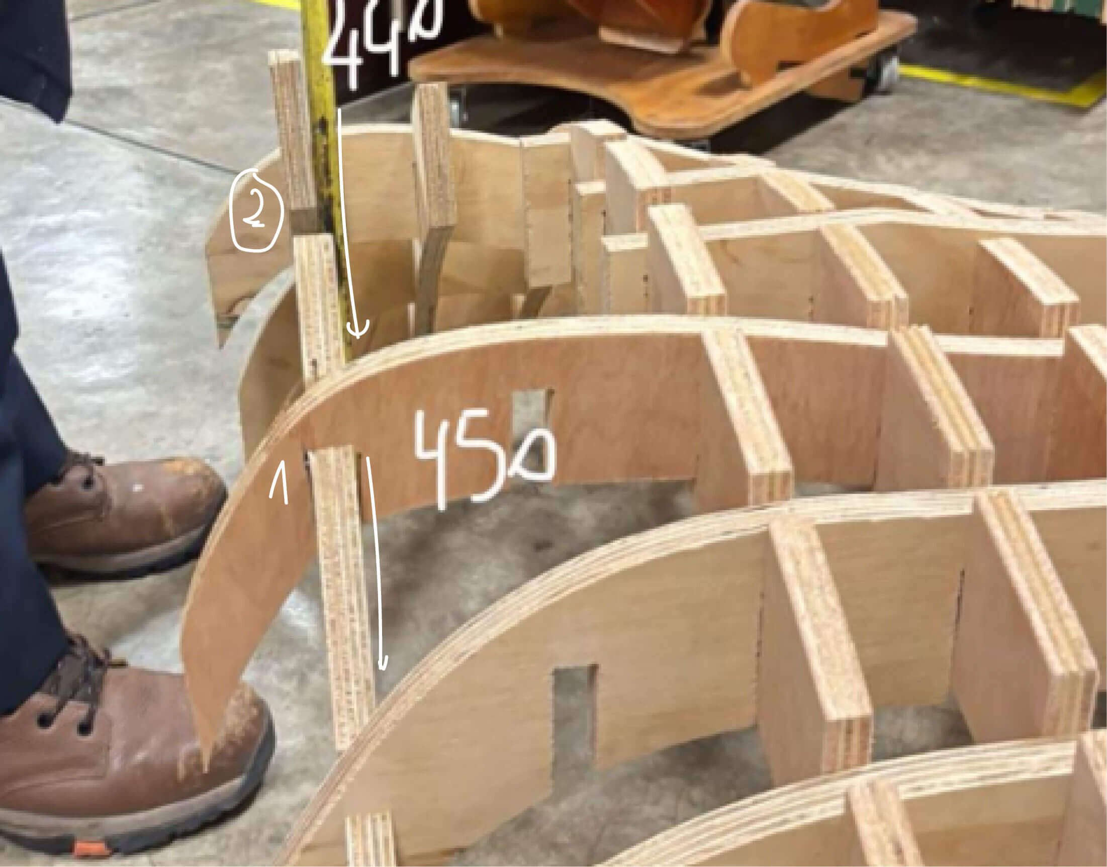
To design the support, I turned the table upside down and carefully measured each end from the floor (which would be the base of the table) so that all sides reached the same height. This allowed me to identify that all eight supports were misaligned. 😲
Gcode for the 2 supports and a missing piece
The support design make it stable enough to have each side the same height. It also defined the space for the plants pots.
Support works fine!
Acrylic CNC milling
Once the table was stable in the correct orientation. The supports made the table base stable, so the four corners were at the same height. Therefore, the acrylic to be fitted had to have holes at the same height as the four pieces that would hold it.
Acrylic design
For the acrylic the settings change for height and depth.
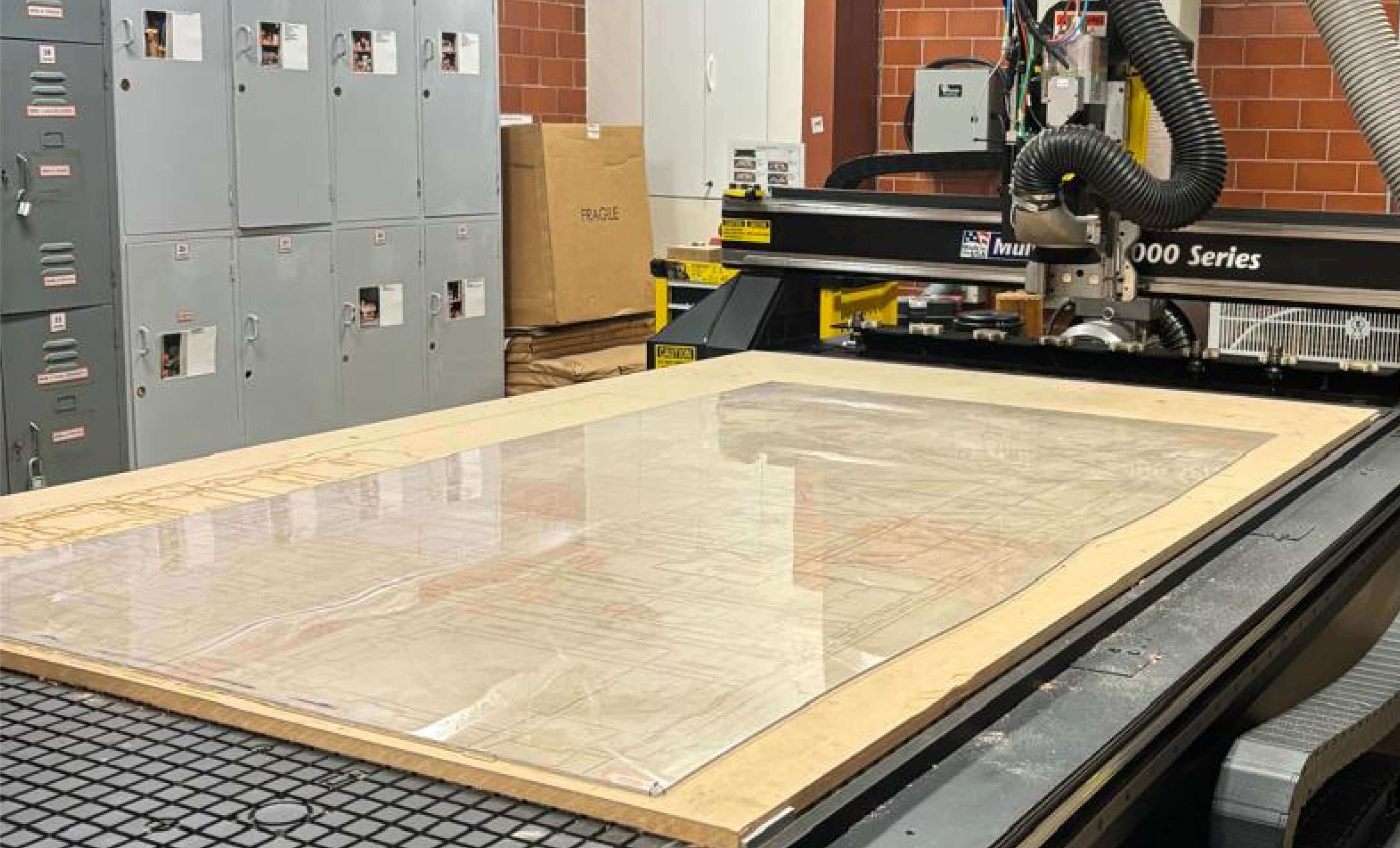
The acrylic placed in the CNC machine.
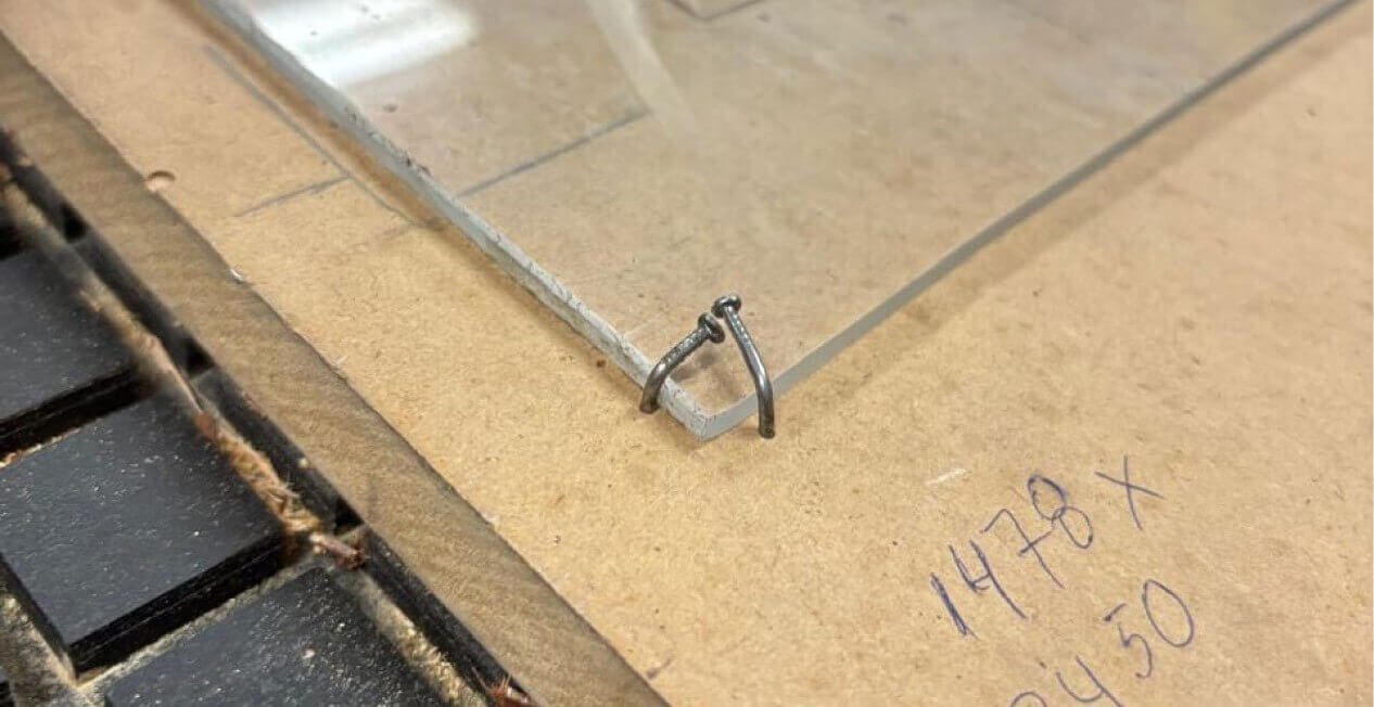
On the instructors' recommendation, I secured the acrylic by bending some nails at each corner so that it wouldn't move during cutting.
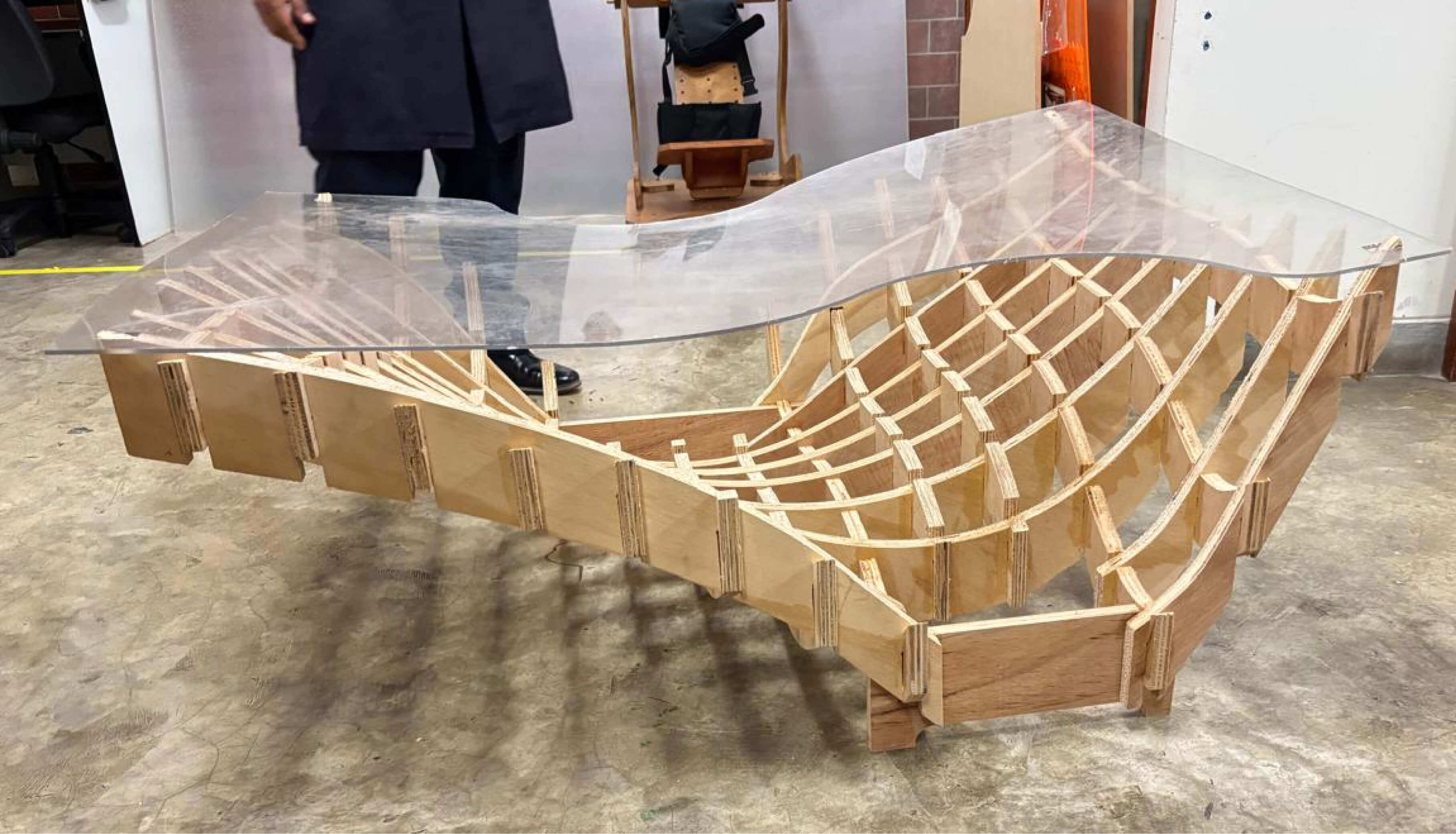
The acrylic fit perfectly and tightened the corners, giving it greater support.
f i n a l S H O T S