Assignments
- Design and document the system integration for your final project
f i n a l P R O j e c t In Th e M A K i n g
A ✨ L I G H T ✨ & ✨ C O L O R ✨ C O M B I N A T I O N ✨ S C U L P T U R E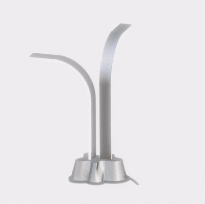
A modular light sculpture that changes color as you assembly it and by sound. Bringing an art experience with color combination by light.
i d e a & d e s i g n
Idea evolved in week 3
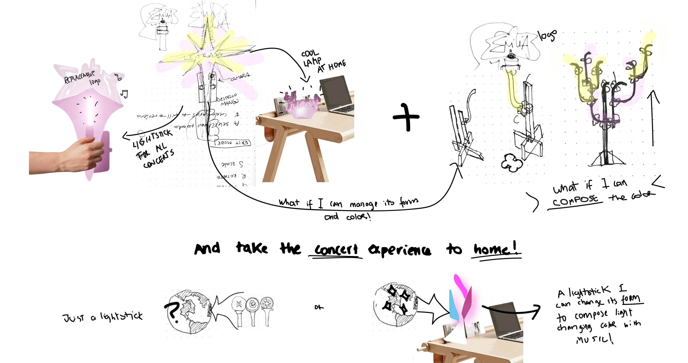
The first idea was to make a "universal lightstick for concerts" but I was stucked in the concept of the typical lightstick and I was far from the idea of evolving my art art with sculpture and technology that is the main reason why I decided to join since is the journey I want to follow in my proffesional path.

idea sketches from my cyanotypes vectors
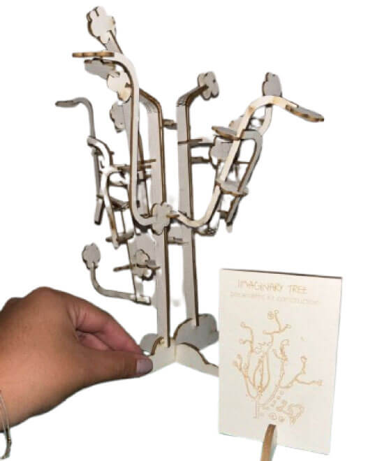
Then, after week 3 everything made sense. I made the parametric kit construction from one of the characters I draw about cities in my personal art project called: My Cyan Cities. So, I tought about combining both concepts and make a light sculpture from this modular construction kit that reacts to music (and therefore to environmental sound) and to take thelight experience of concerts (that is one of my favorite things ever) to my home!
s y s t e m
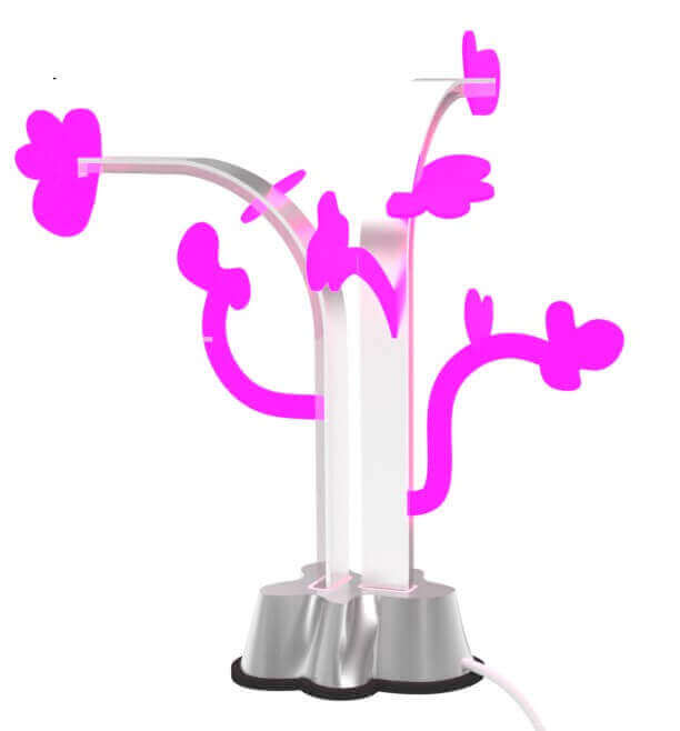
I organized the system for my final project as a sculpture that reacts to light and sound. As input, I'll need a microphone sound sensor, and as output, the RGB LEDs and RGB strips that will be the branches and petals of the tree sculpture. The idea is for the petals and branches to be independent, so I can assemble the tree and change it each time since it's modular.
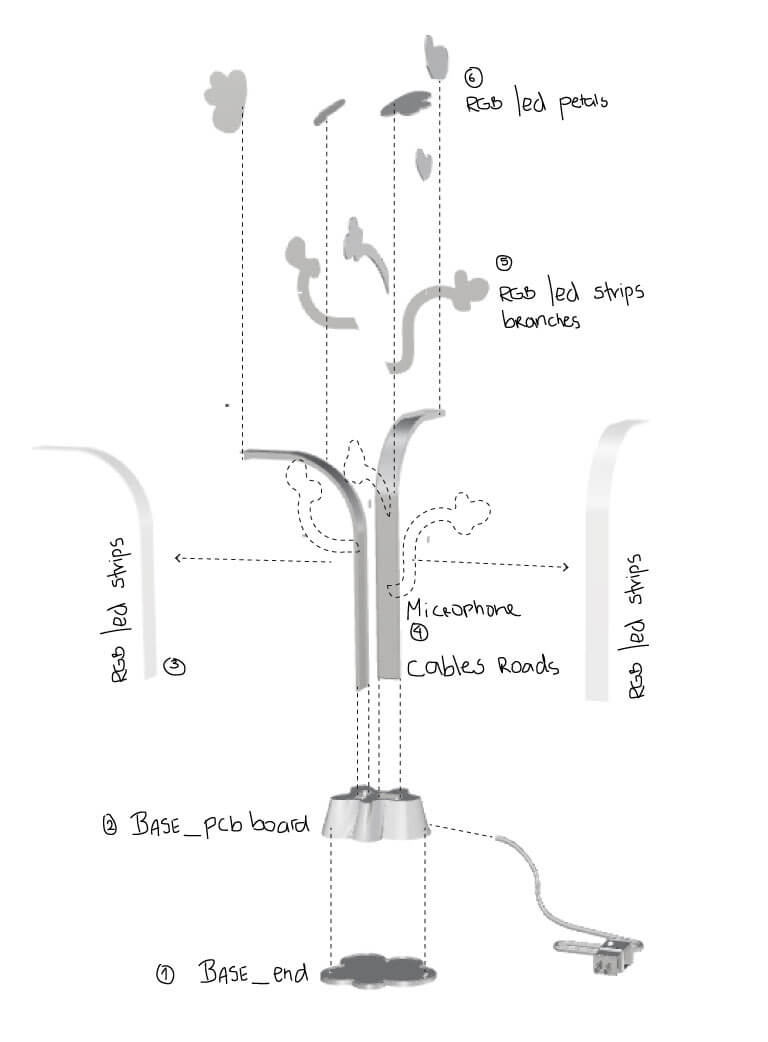
I divided the system into 6 parts:
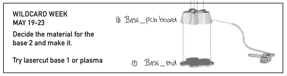
- The base: The first part of the base is divided into two, but both processes will be printing and laser cutting or plasma cutting. I need a rigid base that can hold weight and keep all the pieces in place.
- PCB board location:This part of the base needs to be wide and tall enough to fit the first pieces and accommodate the PCB square and the start of all the connections. I've given it approximately 8 cm of height for all these connections.
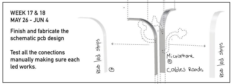
- Cable roads and microphone location: The first pieces that fit into the system are the tree stems. These must be as heavy as the base because they will be constantly replaced. This is where I will route all the cables that will connect the petals and subsequent branches. Likewise, the microphone must be placed on one of these pieces, as it must be at the center of the project to best receive sound.
- RGB led strips:These same stems will have fixed LED strips which illuminate the entire base of the sculpture.
- RGB led strips branches:Here begins the modular pieces, which are interchangeable. I'll have three branches that will be small LED strips that react when they touch a petal.
- RGB led petals:Finally, the petals are the pieces that activate the color change of the project, and the microphone changes the rhythm of turning on and off and its intensity.
p i e c e s & f a b r i ca t i o n
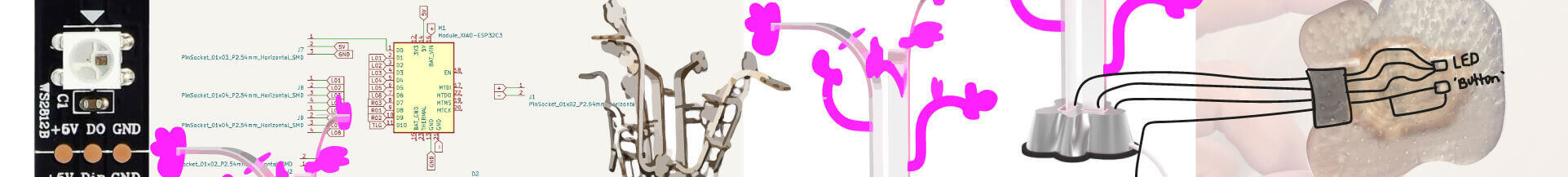
I N T E R N A L S Y S T E M
For the internal operation of the project. Based on the XIAO ESP32-C3, the sound sensor microphone is used as input and the RGB LEDs are used as output.
| q | Purpose | |
|---|---|---|
| energy source | 1 | Find the correct energy source for all the conections. It may be a battery. |
| XIAO ESP32-C3 | 1 | I alredy tried with this microcontroller all the assignments. |
| RGB Leds | 6 | For the modular and changable petals. They will work regardless the rest of pieces. |
| RGB Led strips | 5 | For the base of that modular petals. Before them the base should illuminate with sound. |
| Pin sockets and headers | 18 | As I will have changable pieces I need conection for every led rgb conection. The sockets are strong enough to keek the variable conections. |
| Microphone sound sensor | 1 | All the lights will react to sound, so from this depends the color changing and intensity of the sculpture. |
| Switch | 1 | To turn on and off the sculpture. |
I have alredy make some tests with the rgb leds and the form of the petals. However I was finding difficult to have lots of modular pieces to change the color because each rgb led need 3 pins of the microcontroller. And the XIAO just has 10. So after searching a lot I found that the rgb leds only need 1 pin apart from vcc and gnd. So I will cut some independent leds from the led strips and make them petals.
S C H E M E I D E A f o r t h e R G B l e d s
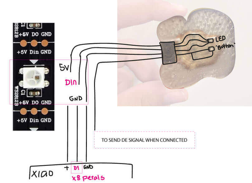
I still need to find a way to send the signal when the petal is connected so the system knows when to change color. I have been thinking with my instructors about recreating the circuit of a button. Because it sends a signal when pressed, so I need to connect the same route to make the microcontroller think it has receibed a button change state when in reality is just a new piece connected.
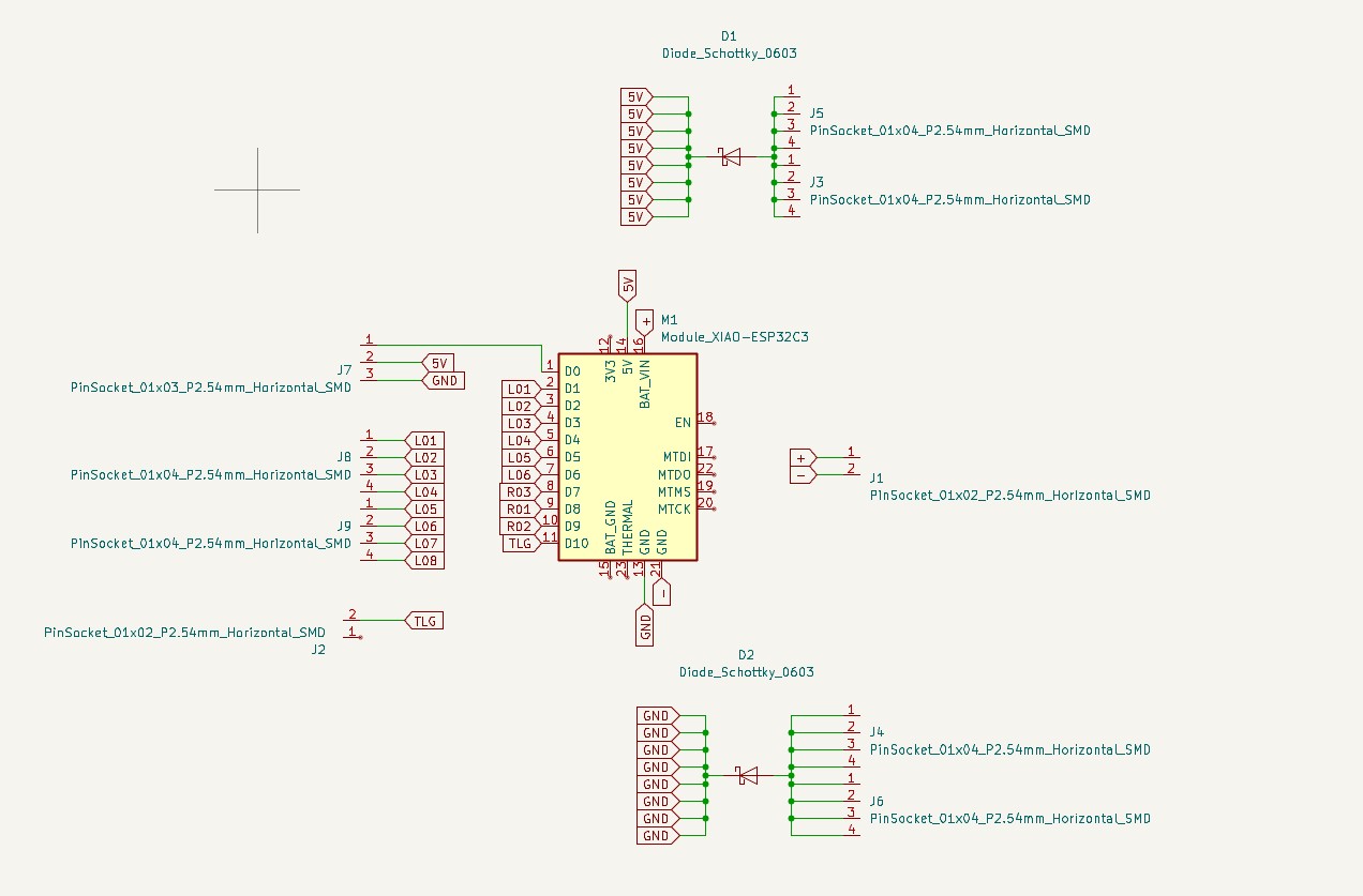
I alredy have the schematic design for the system. However I still have to figure it out the conections for the "connected signal" and all the components I will have to had separately from the pcb board such as the switch and the battery and each pin socket for each petal.
E X T E R N A L S Y S T E M
I also organized the external pieces and fabrication processes I need to do.
| q | Material | fabrication process | |
|---|---|---|---|
| base 1 | 1 | transparent acrylic or something heavy | Lasercut / plasma |
| base for the XIAO ESP32-C3 | 1 | white PLA or something with a metallic finish | 3d printing or metal process. |
| Principal branches | 1 | metallic finish but transparent case to see all the organized cables crossing | Transparent 3d printing. |
| RGB branches | 1 | transparent acrylic | lasercut |
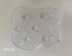
| RGB petals | 6 | transparent resin to have the light difuse by the layers of printing. | resin 3d printing |
F A B R I C A T I O N
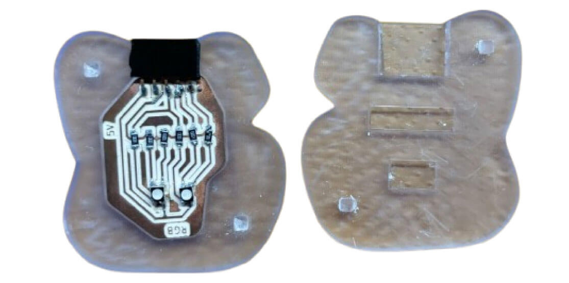
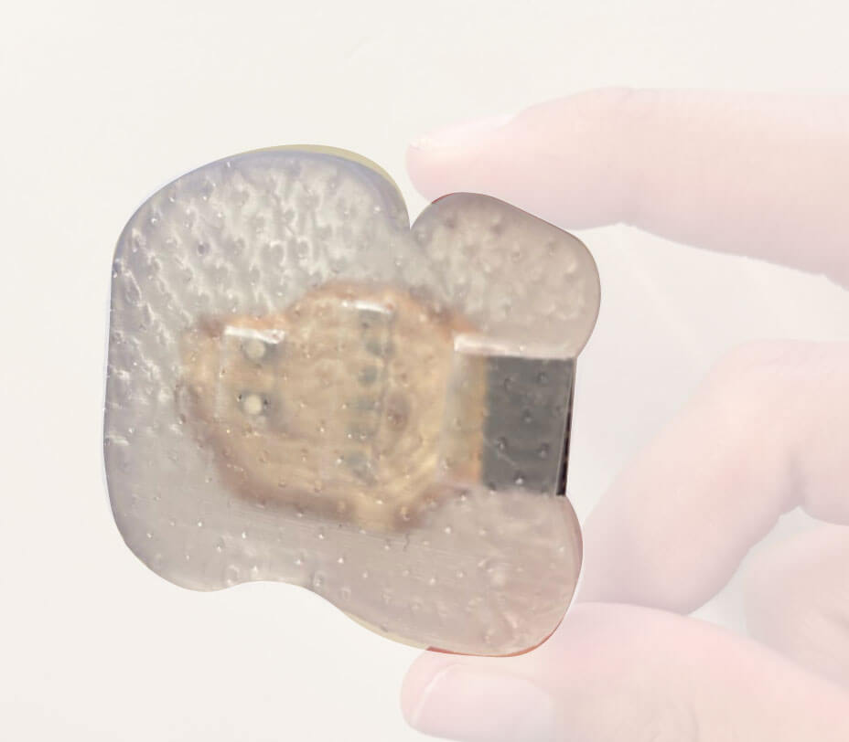
I alredy have the material, measures and pcb boards system for the color change petals. In week 8 I tried with different materials a case for the pcb boards in a form of petal. I like the clear resin finish.
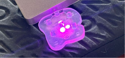
And now I have just made a more complete prototype fot the petlas with the correct footprint to fit the pcb board and with everything filled but with an space fot the leds to reflect the light.
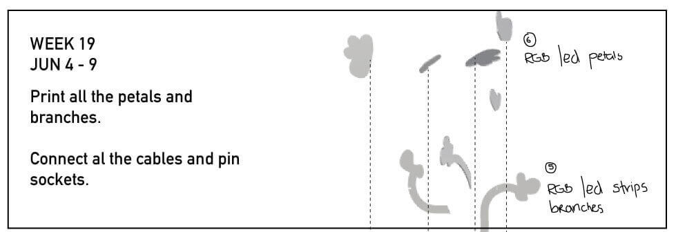
s c h e d u l e
I organized the time by pieces. First I need to finish the base to make sure where is going to fit the pcb board.
Then I need to fabricate all the branches and for this I have to confirm the connections manually and figure the pin sockets locations in the internal design.
I left the petals for the end because I have alredy had a test of this in Week 10 output devices where the case and led worked fine. So I will replicate this case in transparent resin for all the petals.