
Assignments
Group Assignment
- Compare as many tool options as possible.
Individual Assignment
- Write an application that interfaces a user with an input &/or output device that you made
GROUP ASSIGNMENT
More specific detailed from the worked done with Ernesto Castro in Fab Lab Universidad de Lima here
M I T a p p I n v e n t o r
We both tried AppInventor since we did not had any experience in making an application and everyone said it was easy to use. However we found it difficult to understand the blocks part. The interface for seign was really easy to find out.
First steps to understand the app: Ofelia
- Turn on the bluetooth connection ☑
Bluetooth conection app from template
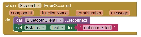
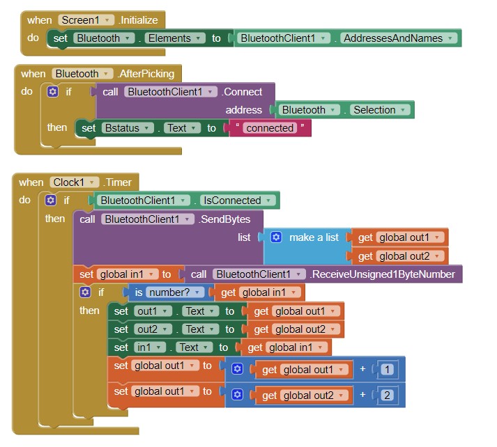
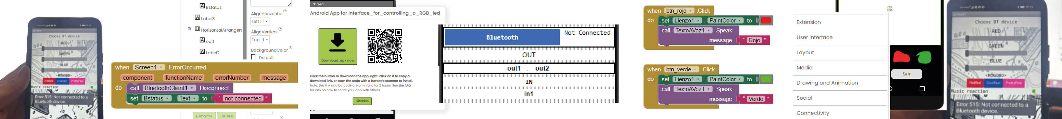
I download a template for Bluetooth connection from the APP INVENTOR repository. I did this because I did not understand how to start in the blocks section. I change the design of the interface and then in the blocks understood to first state the status connection of the bluetooth. And then to programm the different stages when connected and when not.
- Find a template and change its funtions ☑
Sketch app from template
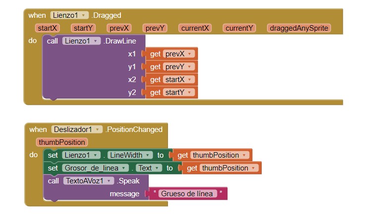
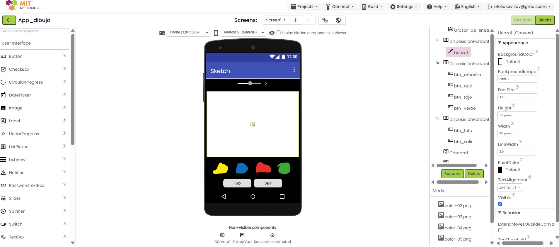
In this template, I added my color palette images, paint splatters I drew in Illustrator and added as PNGs. The block design was simpler and more straightforward to understand.
Bluetooth conection app from template
I download a template for Bluetooth connection from the APP INVENTOR repository. I did this because I did not understand how to start in the blocks section. I change the design of the interface and then in the blocks understood to first state the status connection of the bluetooth. And then to programm the different stages when connected and when not.
Sketch app from template
In this template, I added my color palette images, paint splatters I drew in Illustrator and added as PNGs. The block design was simpler and more straightforward to understand.
F i r e f l y
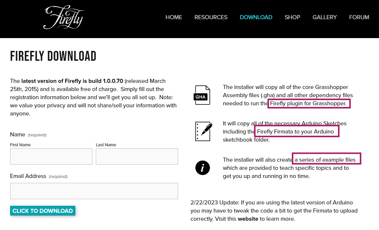
For the group assignment we had to compare another tool. Since we both try MIT APP Inventor first I try Firefly because I research it can be use with grasshopper, a software I am familiar with. I download it from here and followed this tutorial to start with.
Bluetooth conection app from template
From the download files there is a guide to start in Grasshopper:
-
Launch Grasshopper in Rhino and Click on File>Special Folders> Components Folder
- Open the Firefy Installation folder that was just downloaded (in the zip folder) and copy all the contents of the Firefly Build folder (Firefly.gha, Firefly_X.gha, Firefly_Bridge.dll, libTUIO.dll, and C_sawapan_media.dll) into the Components Folder that was opened from within Rhino.
- Restart Rhino and Grasshopper
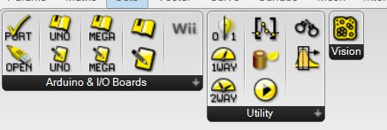
Then in Grasshopper you will see this new commands:
From the download files there is a guide to start in Arduino with Grasshopper:
-
Plug Arduino boards into your USB port; confirm that your Arduino's green power LED in on.
- Select your specific Arduino Board and Serial Port (Tools > Board; Tools > Serial Port) *Take note of your Serial Port COM #
- Verify (play button) and Upload (upload button) this program to your Arduino, close the Arduino program
- then open ... Rhino/Grasshopper/Firefly
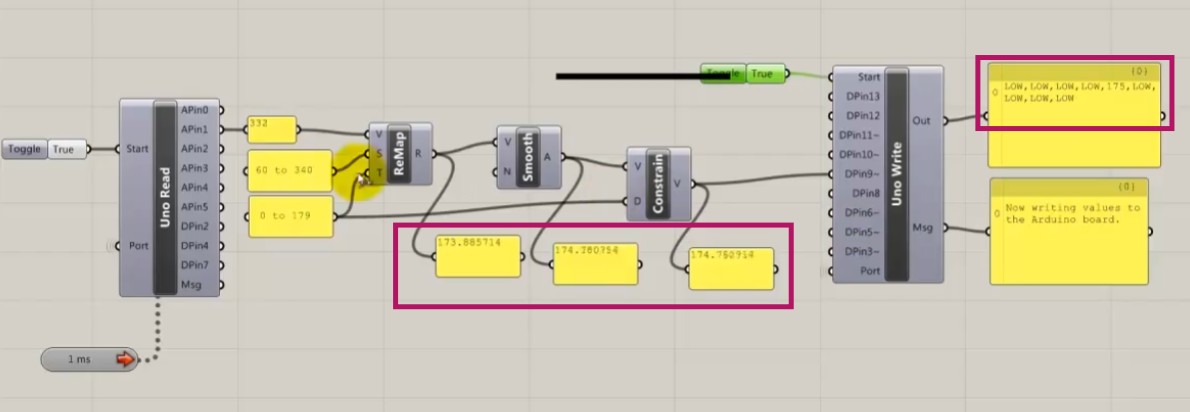
From the same download files I opened this example to control a led by a switch
:
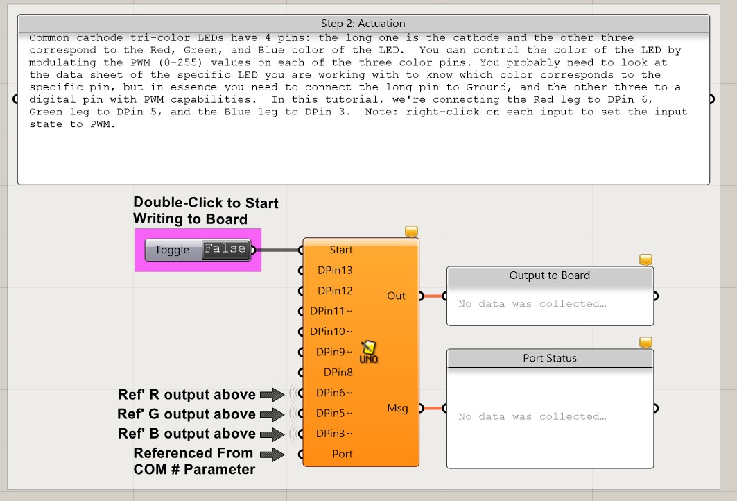
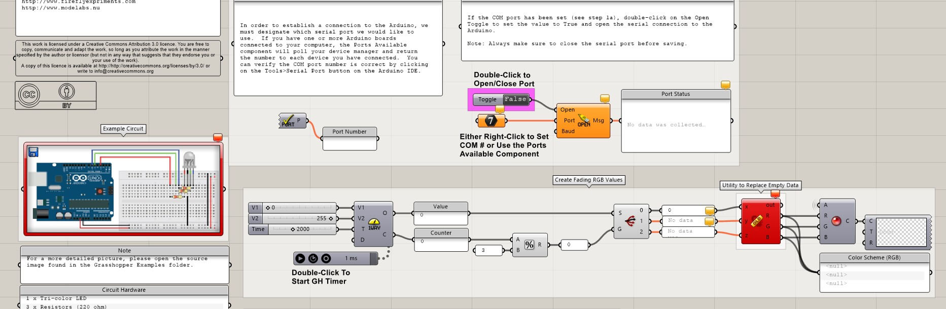 And realized first in grasshopper needs to connect by the port numer and then with the ARDUINO UNO command I start the communication and determined the pins of the output.
 Here is the complete example I research from this tutorial and I hope to try it too:
CONCLUSION:
I found it really complex with APP Invetor trying without a template in the blocks stage. In the design stage I found it really easy to decipher as it looks like editing software. Buetooth conection of course has its own complexity for the programmation. Doing the sketch app was really easy as the components just work by themselves and I do not have to figure out what to connect as in the Bluetooth app.
While with Firefly I do understand the process because its with grasshopper however the part to communicate with the arduino I am still figuring out and I do get how to communicate but not how to make an interface as with APP inventor.
INDIVIDUAL ASSIGNMENT
Final design of the rgb control led app made by me.
I stay in App Inventor as it was really difficult to figure it out. And I really liked the design stage where I wanted to try more components as sliders. I made an app to control the color in the RGB LED pcb I made in Week 10.
p r o c e s s : D E S I G N

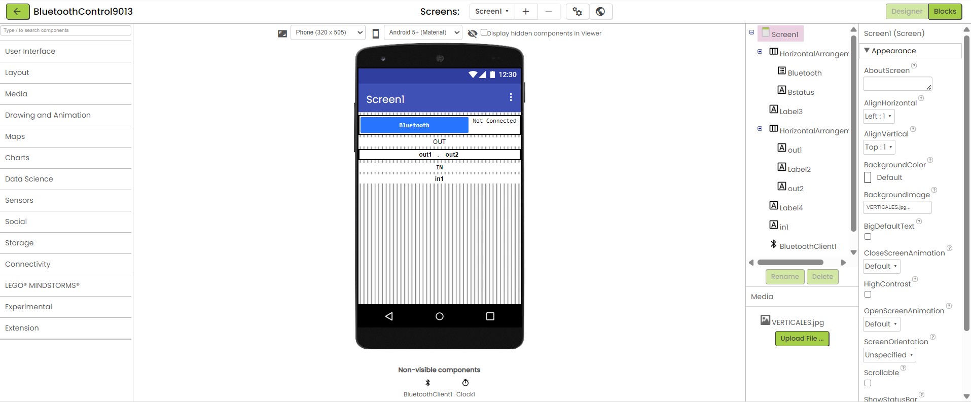
APP Inventor design stage
First I sign up to MIT App Inventor from https://appinventor.mit.edu/ and searched for a rgb led template to understand how blocks worked. However the template I used just turned the leds on and off for red, blue and green.
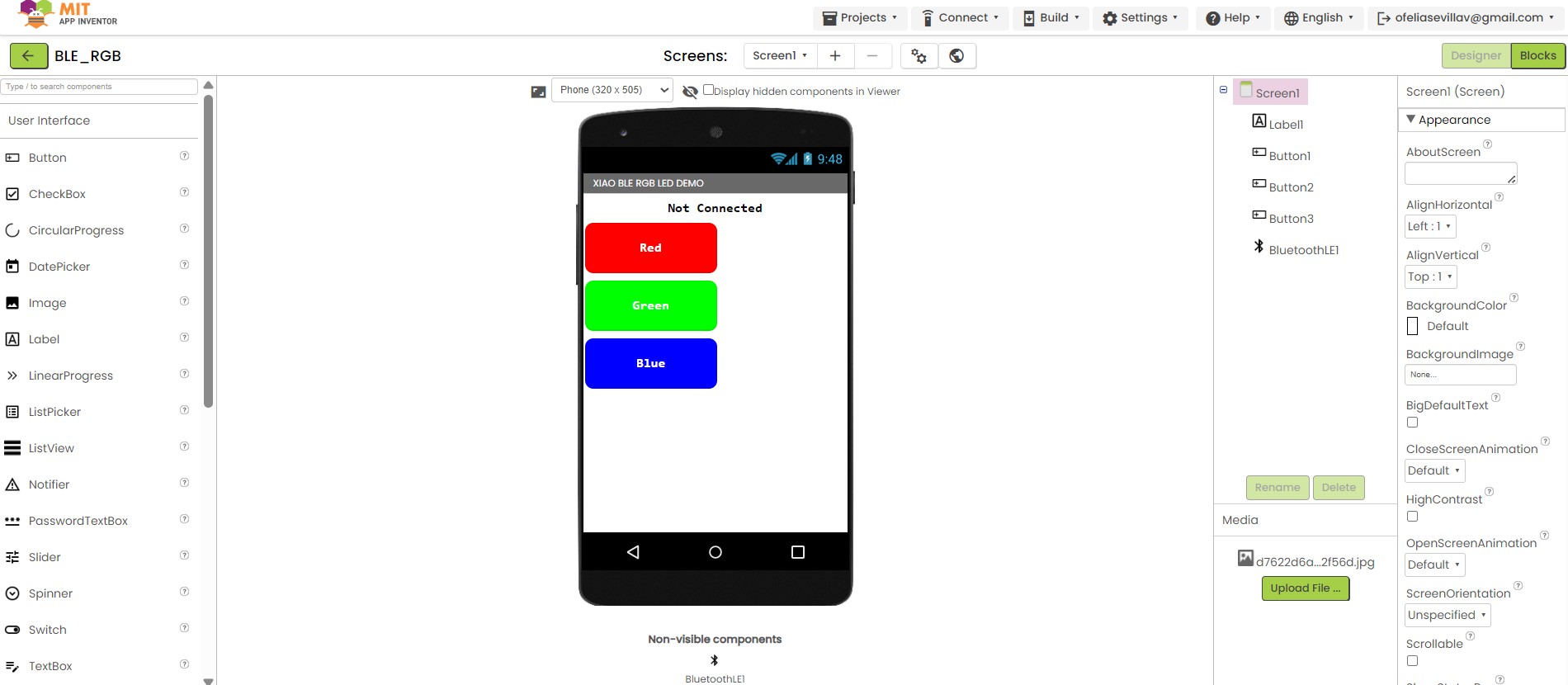
rgb led template
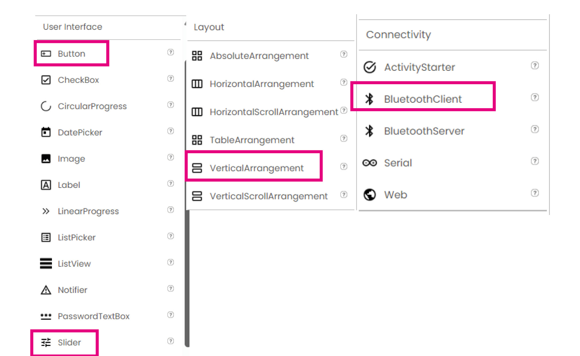
To understand how to edit the components Ichecked in the left there are some options to add buttons, sliders, etc. And a way to organize them in horizontal and vertical. Also here was really important to connect BluetoothClient to start the bluetooth connection.
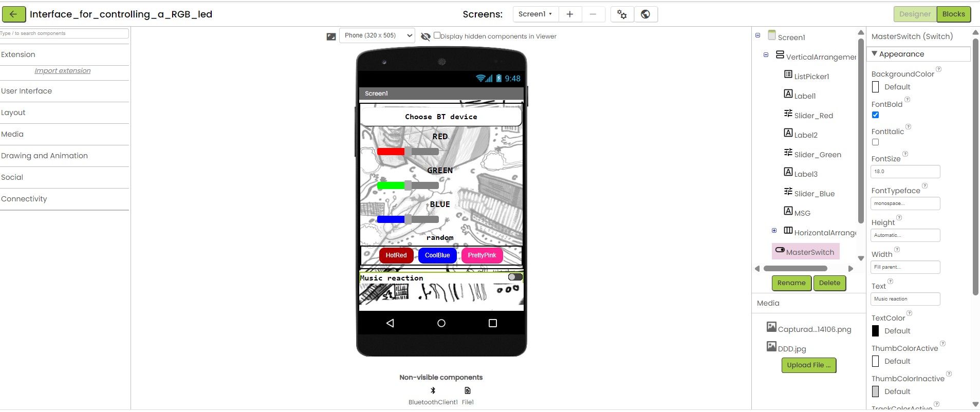
After inserting all the components I wanted I needed to customize them as I wanted the app to look like. I also tried to visualize it as a tablet screen to see how it will fit.
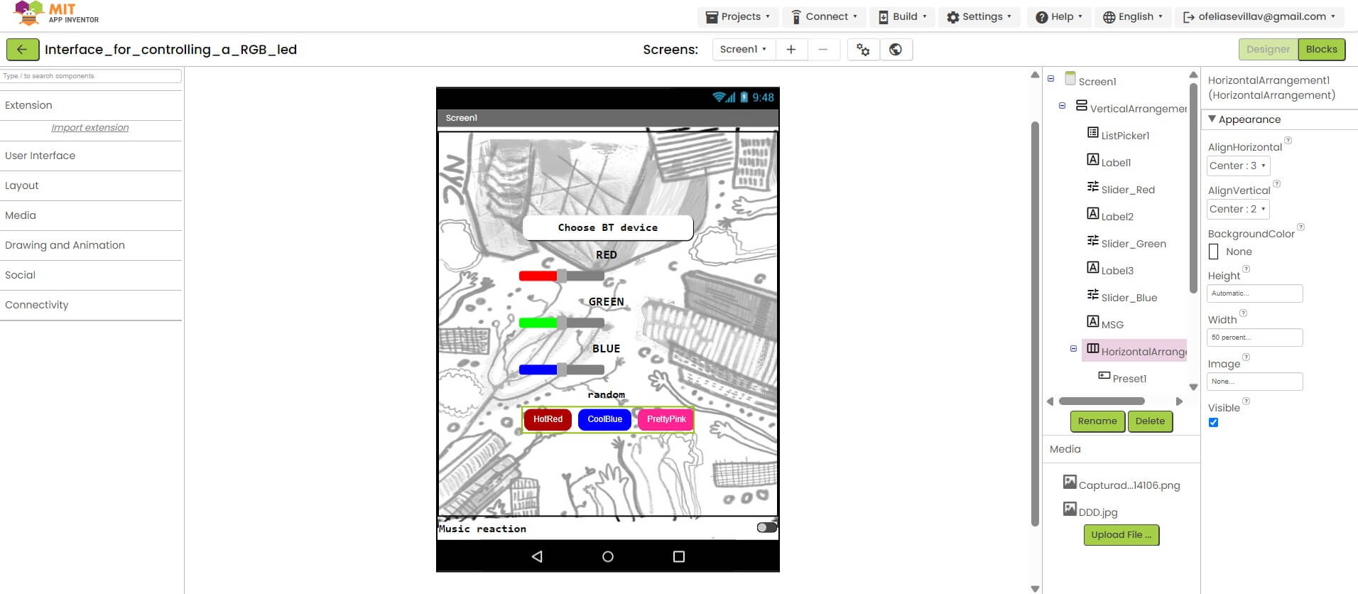
rgb led template
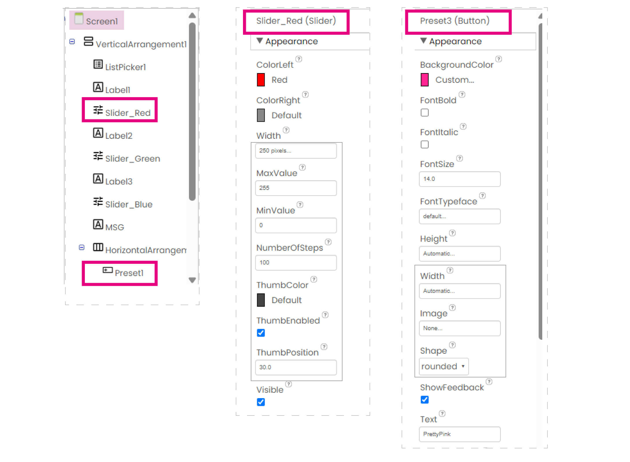
In the left while clicking each component there displays new editing options such as width and height of the buttons, shape, color background, font, size and more. I try to put some of my drawings as a background image and everything round shape in the center and it turned out looking good!
p r o c e s s : B L O C K S
changing to blocks stage
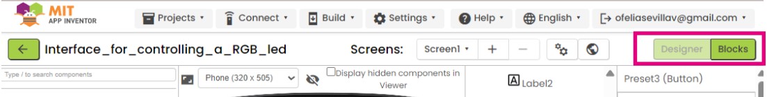
After having the design done to make each component work there is a new window called "blocks" where you programm everything as blocks. In the right up corner there is a button to change stages.
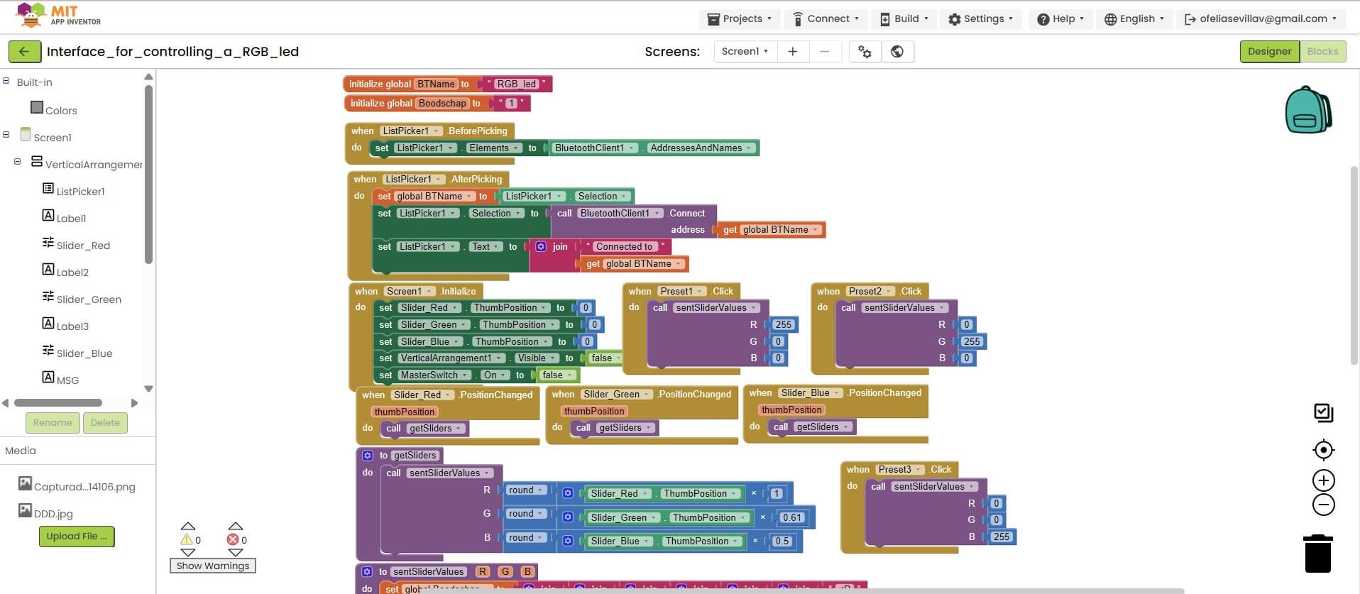
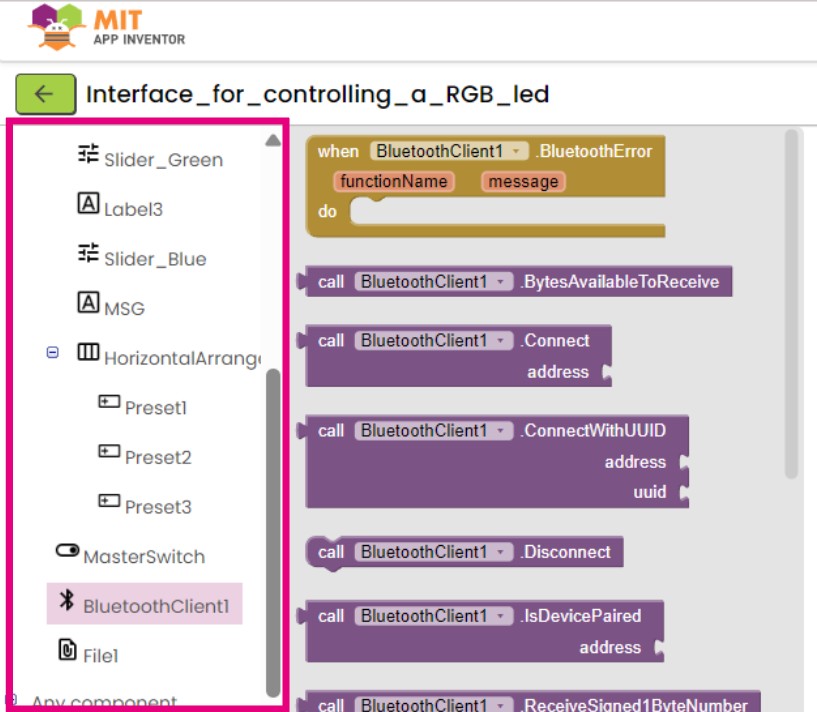
To start programming in the left side there will appear each component. By clicking one in the right will appear some possible options to programm. First I started the bluetooth connection and what really help in this software was the fact that each block has specified what to connect and when like puzzle pieces.
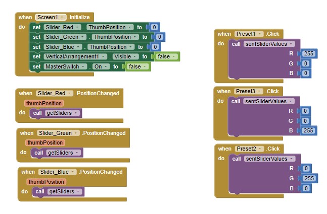
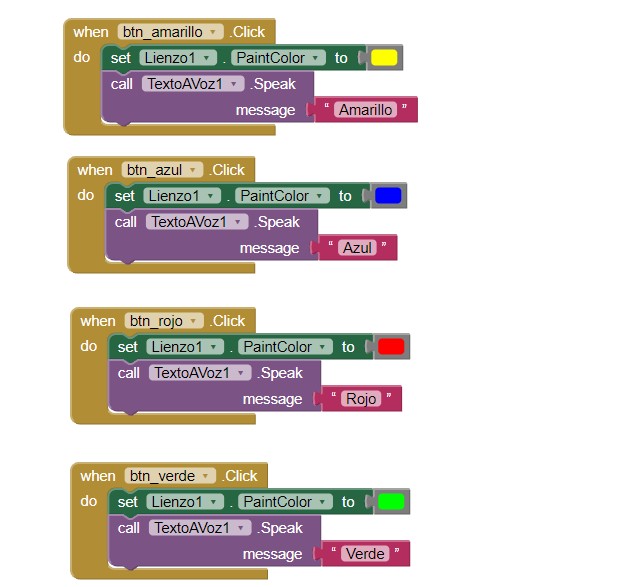
Finally I had to search a lot about how to make the sliders change color and how to stablish the rgb preset color for the 3 buttons. Basically I had to first initiate the sliders and then call each for an action.
T E S T S
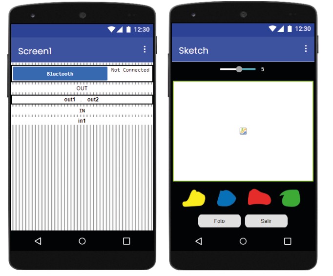
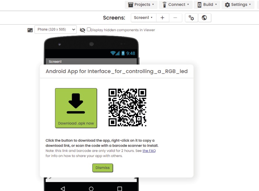
To test the app is better to have an Android. In IOS the app did not worked. I made the link to download the app directly in the device, as I could not find the app to try this. I download from the qr.
APP Inventor design stage
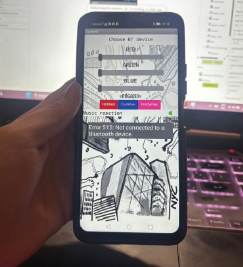
App in Android
What's next?
Test the app in the pcb board and change colors.Try to make and undesrtand the blocks stage with grasshopper and firefly.
CONCLUSION:
I found it really complex with APP Invetor trying without a template in the blocks stage. In the design stage I found it really easy to decipher as it looks like editing software. Buetooth conection of course has its own complexity for the programmation. Doing the sketch app was really easy as the components just work by themselves and I do not have to figure out what to connect as in the Bluetooth app.
While with Firefly I do understand the process because its with grasshopper however the part to communicate with the arduino I am still figuring out and I do get how to communicate but not how to make an interface as with APP inventor.
INDIVIDUAL ASSIGNMENT
Final design of the rgb control led app made by me.
I stay in App Inventor as it was really difficult to figure it out. And I really liked the design stage where I wanted to try more components as sliders. I made an app to control the color in the RGB LED pcb I made in Week 10.
p r o c e s s : D E S I G N
APP Inventor design stage
First I sign up to MIT App Inventor from https://appinventor.mit.edu/ and searched for a rgb led template to understand how blocks worked. However the template I used just turned the leds on and off for red, blue and green.
rgb led template
To understand how to edit the components Ichecked in the left there are some options to add buttons, sliders, etc. And a way to organize them in horizontal and vertical. Also here was really important to connect BluetoothClient to start the bluetooth connection.
After inserting all the components I wanted I needed to customize them as I wanted the app to look like. I also tried to visualize it as a tablet screen to see how it will fit.
rgb led template
In the left while clicking each component there displays new editing options such as width and height of the buttons, shape, color background, font, size and more. I try to put some of my drawings as a background image and everything round shape in the center and it turned out looking good!
p r o c e s s : B L O C K S
changing to blocks stage
After having the design done to make each component work there is a new window called "blocks" where you programm everything as blocks. In the right up corner there is a button to change stages.
To start programming in the left side there will appear each component. By clicking one in the right will appear some possible options to programm. First I started the bluetooth connection and what really help in this software was the fact that each block has specified what to connect and when like puzzle pieces.
Finally I had to search a lot about how to make the sliders change color and how to stablish the rgb preset color for the 3 buttons. Basically I had to first initiate the sliders and then call each for an action.
T E S T S
To test the app is better to have an Android. In IOS the app did not worked. I made the link to download the app directly in the device, as I could not find the app to try this. I download from the qr.
APP Inventor design stage