| uthayavelraj@gmail.com
Week 2

Computer-Aided Design

This week focuses on learning and applying Computer-Aided Design (CAD) tools to create 2D and 3D models for digital fabrication. The goal is to explore different design workflows, parametric modeling, and rendering techniques to visualize and simulate projects before fabrication.

1.2D Design

2D Design,refers to the creation of visual elements and compositions within two dimensions, typically on a flat surface. It is a fundamental aspect of graphic design, digital art, and various visual communication disciplines.


1.1.Key Elements of 2D Design:

Source: medium.com
  • Lines: The basic building blocks for creating shapes and forms.

  • Shapes: Two-dimensional enclosed areas defined by lines.

  • Colour: The use of hues, saturation, and brightness to evoke emotions and convey information.

  • Values: The range of lightness to darkness in an image, providing contrast and depth.

  • Texture: The visual or tactile appearance of surfaces within the design.


1.2.Raster vs. Vector 2D Design:


  • Raster Graphic Design: Relies on pixels, suitable for detailed images and photographs but may lose quality when resized.

  • Vector Graphic Design: Uses mathematical paths and points, allowing for scalability without loss of quality, ideal for logos and illustrations.

Outcomes

Understand the difference between raster, vector, and 3D modeling
Experiment with 2D design tools (Photoshop, Inkscape, CorelDraw)
Learn 3D modeling software (Fusion 360 and SolidWorks)
Render and document designs effectively
Reducing the size of images and photos

1.3. Applications of 2D Design:

  • Graphic Design: Creating visual content for branding, advertising, and digital media.
  • Web Design: Crafting the visual layout and elements of websites.
  • Print Design: Designing materials for print, such as brochures, posters, and business cards.
  • Digital Art: Illustrations, animations, and concept art in the digital realm.

1.4. Importance in Various Industries:

  • Marketing and Advertising: Captivating visuals are crucial for effective communication and brand recognition.
  • Entertainment: Used in animation, game design, and film for storytelling and visual appeal.
  • Education: Visual aids and graphics enhance learning materials and presentations.

1.5. Digital Tools for 2D Design I have used:

  • Adobe Photoshop is a powerful and widely used raster graphics editing software developed by Adobe Inc. It has become the industry standard for digital image manipulation, photo editing, and graphic design.

  • Coreldraw is primarily used for graphic design, illustration, and layout creation. It's a vector graphics editor and illustration software that can be used for a wide range of design tasks, including creating logos, posters, websites, and more.

  • Inkscape is a free and open-source vector graphics editor

1.6. Creating a 2D Design on Corel Draw

In Corel Draw I have Created my own design with marking lines and create a Flower shape by using various comands.
Image 1 Image 2 Image 3 Image 4 Image 5 Image 6 Image 7 Image 8 Image 9


Final output :


2. CAD softwares

I used Solidworks and Fusion 360 because :

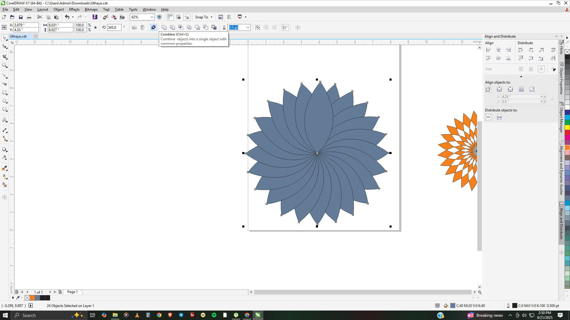
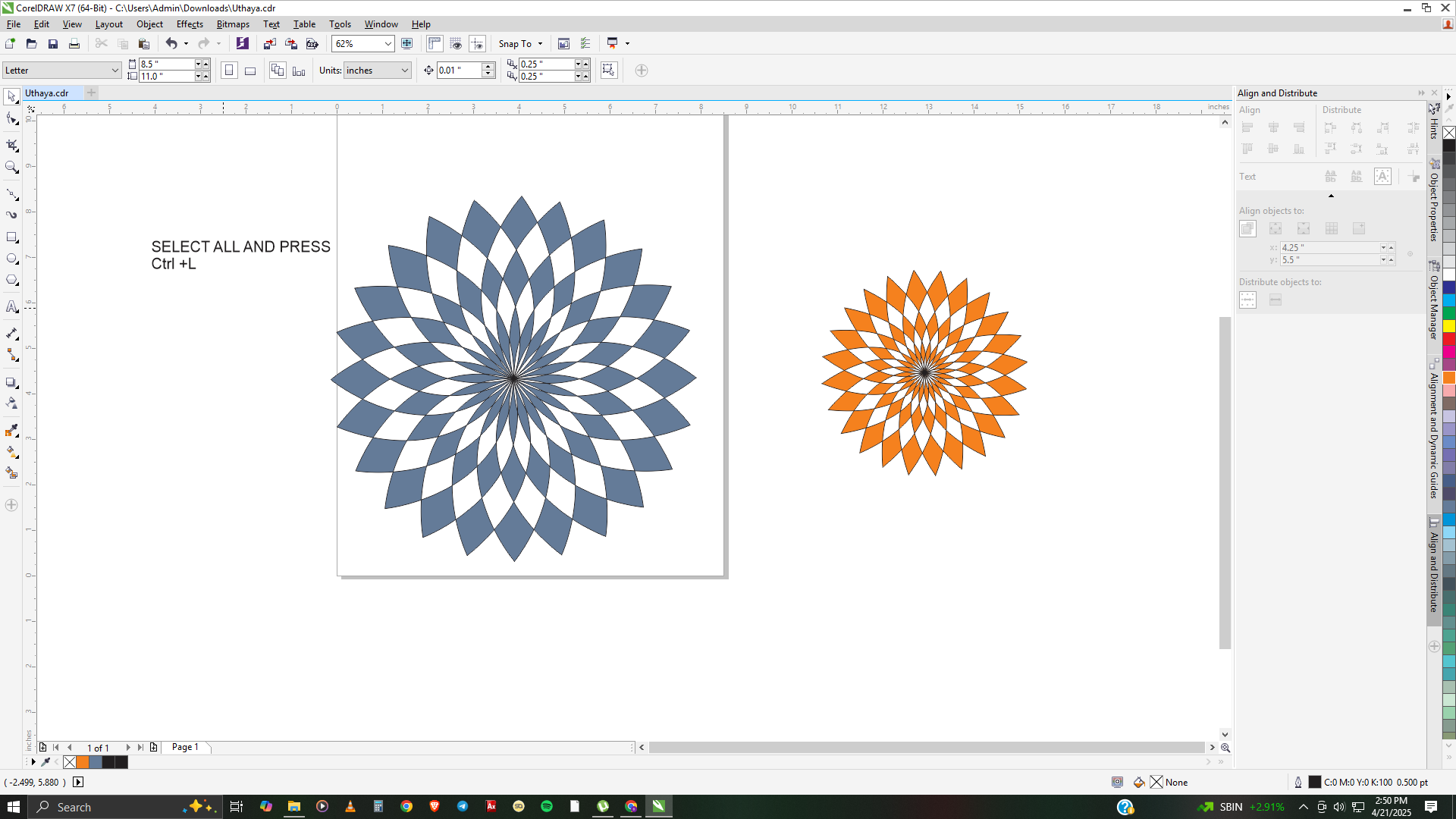
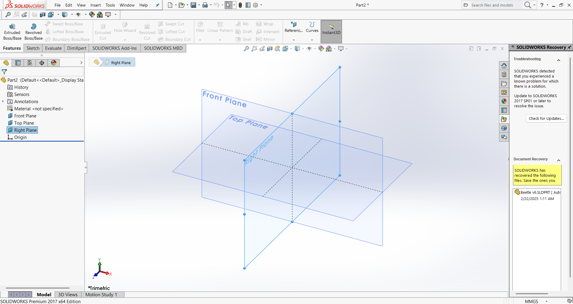
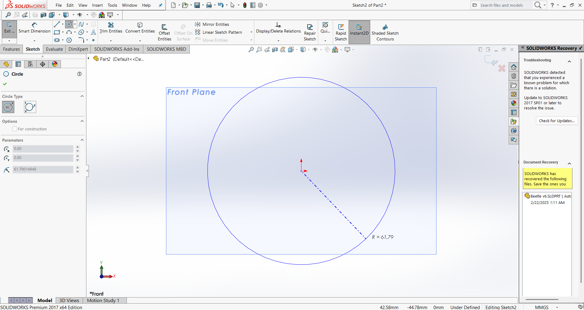
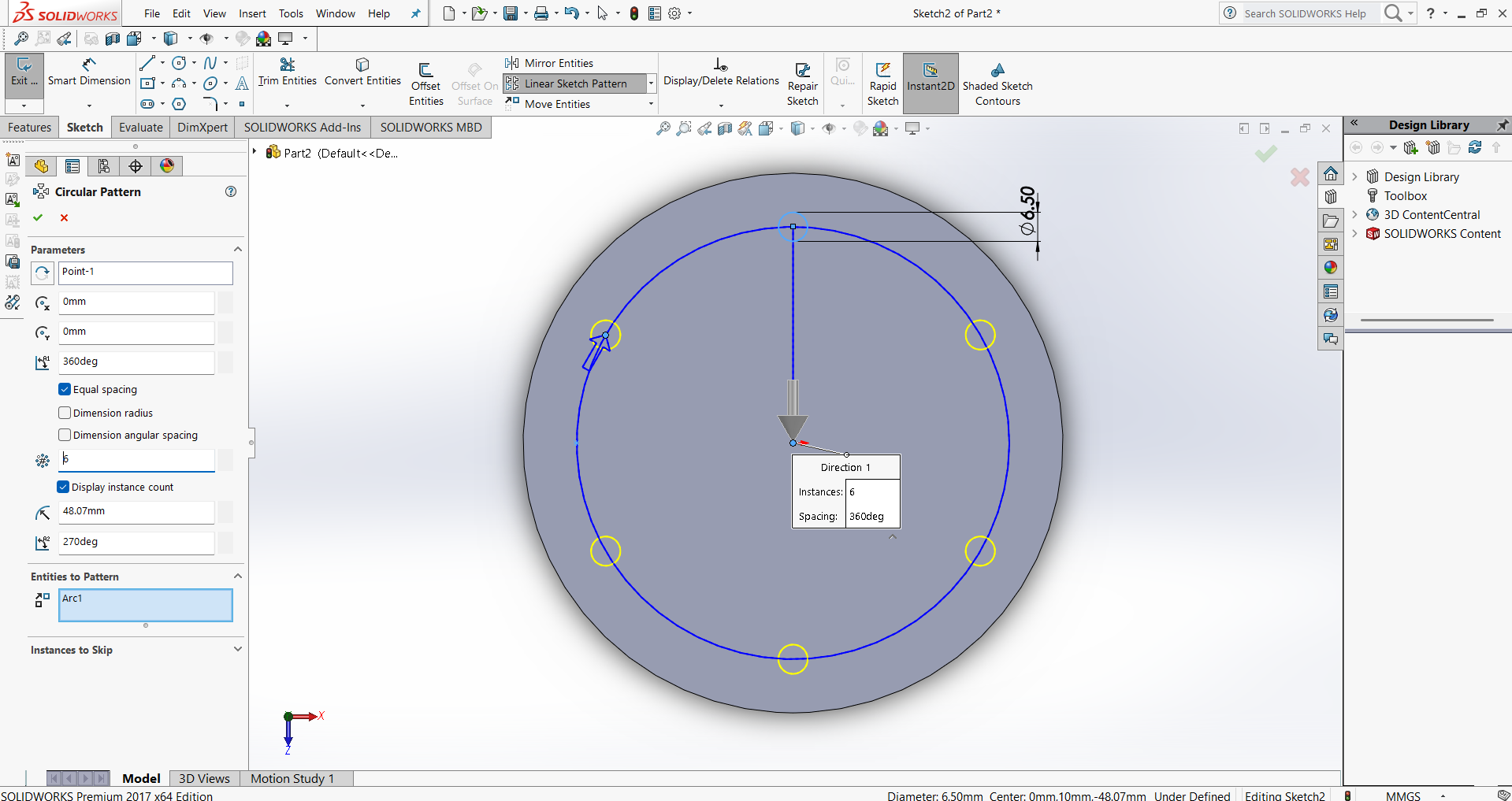
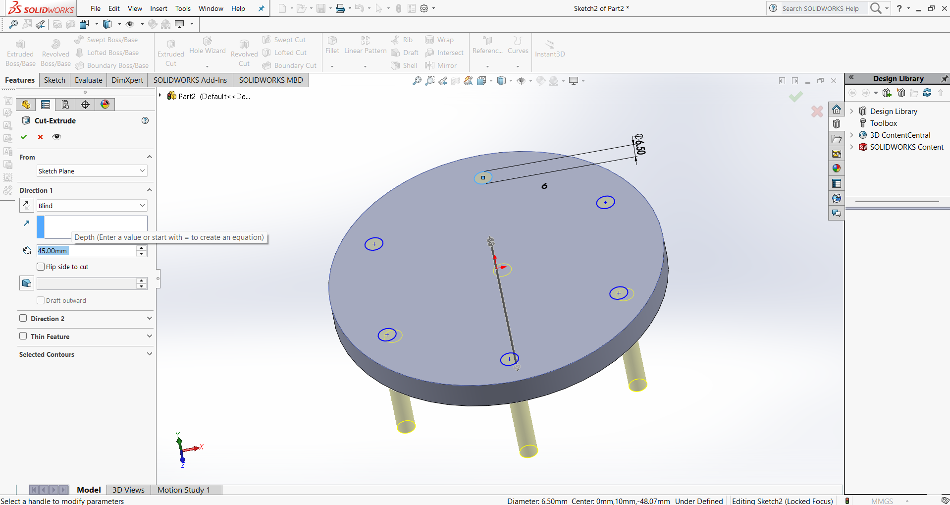
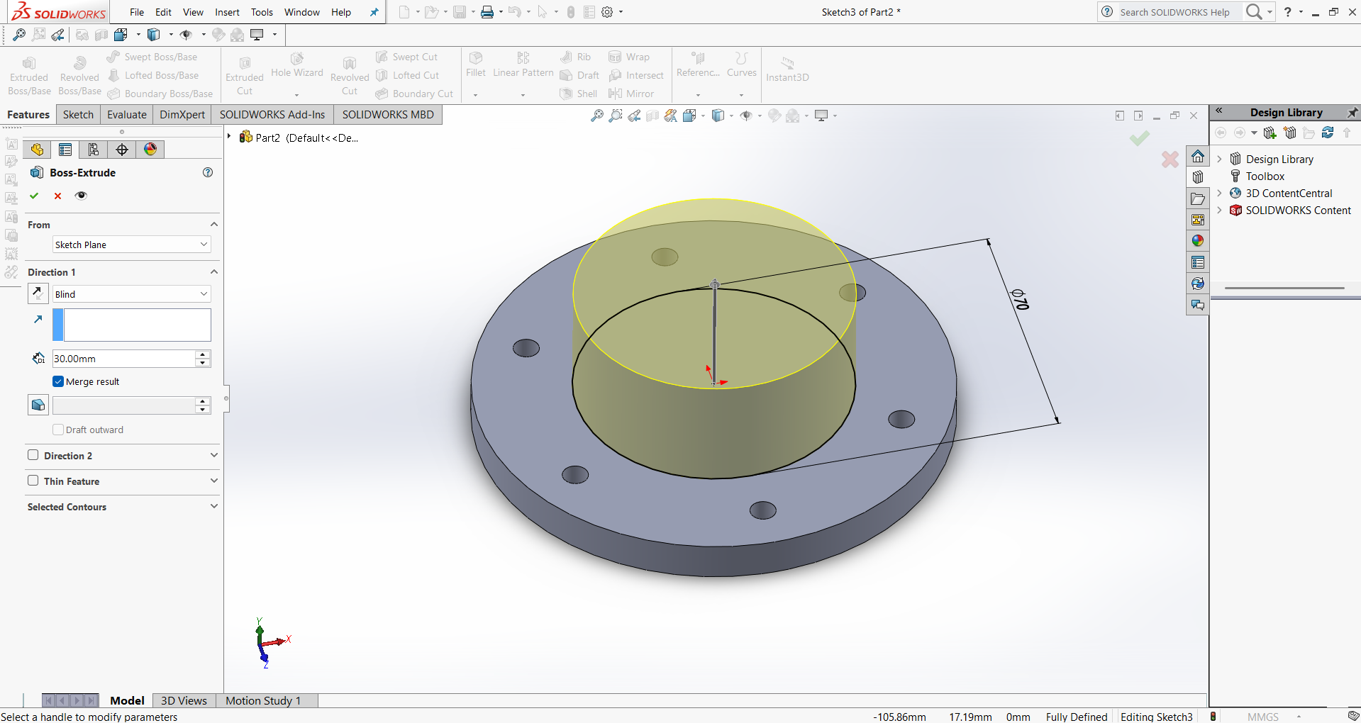
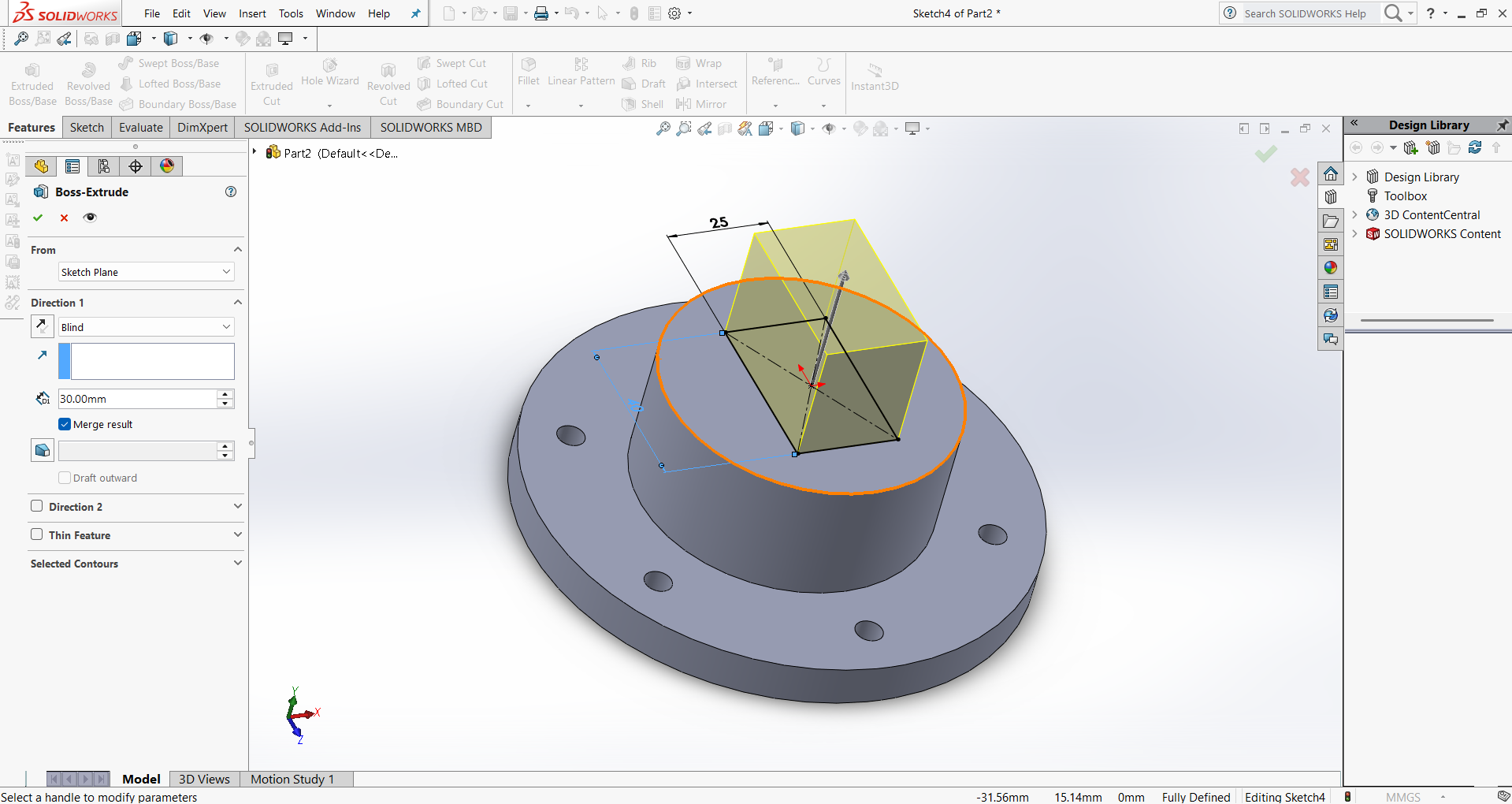
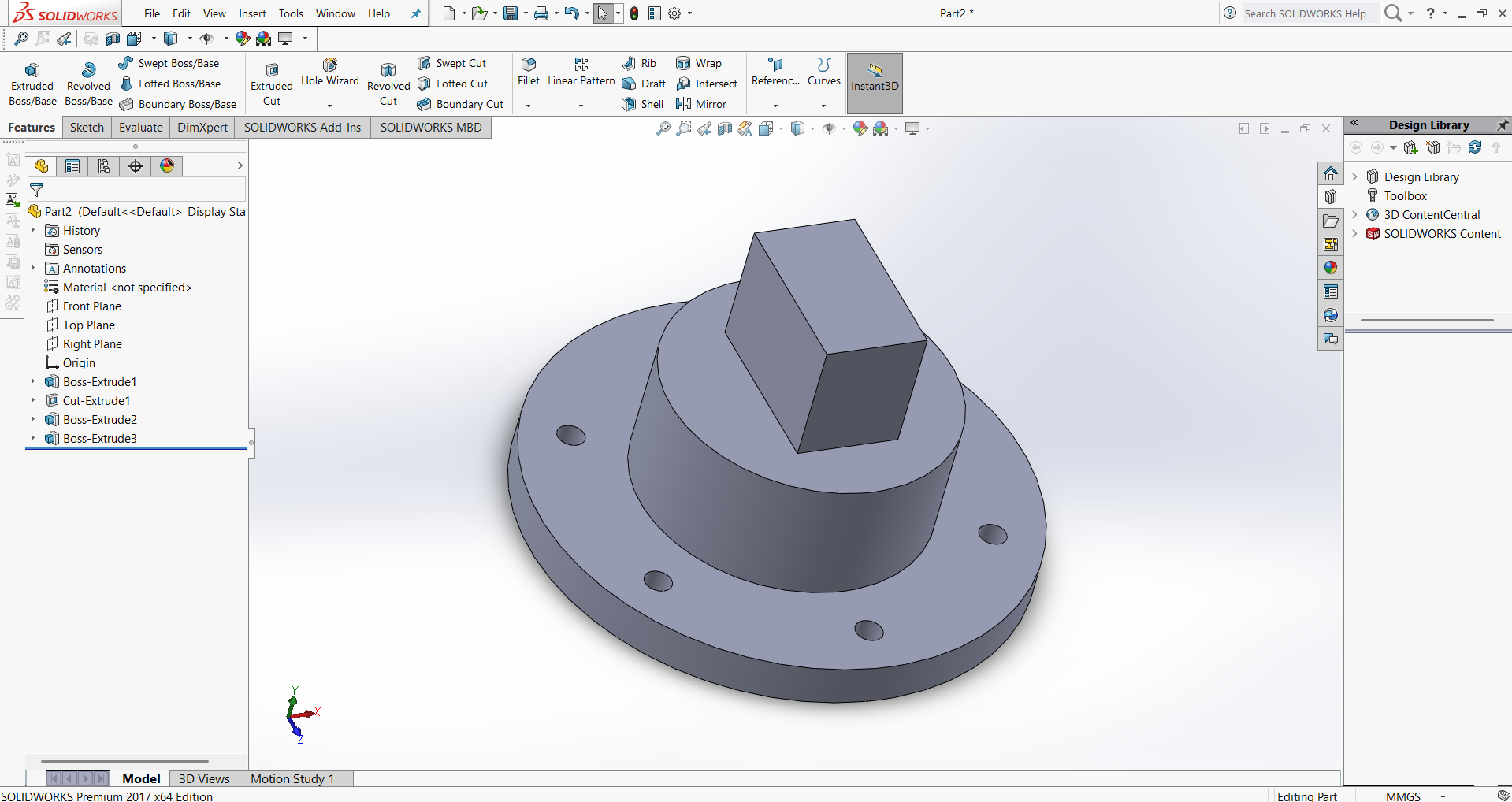
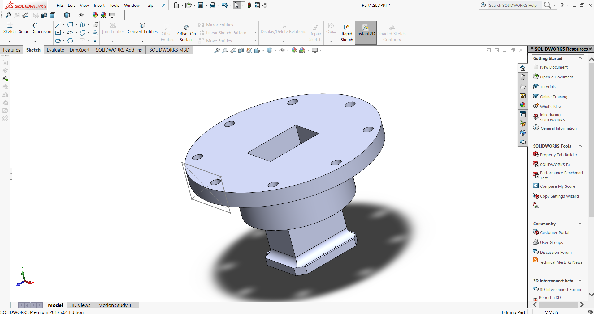
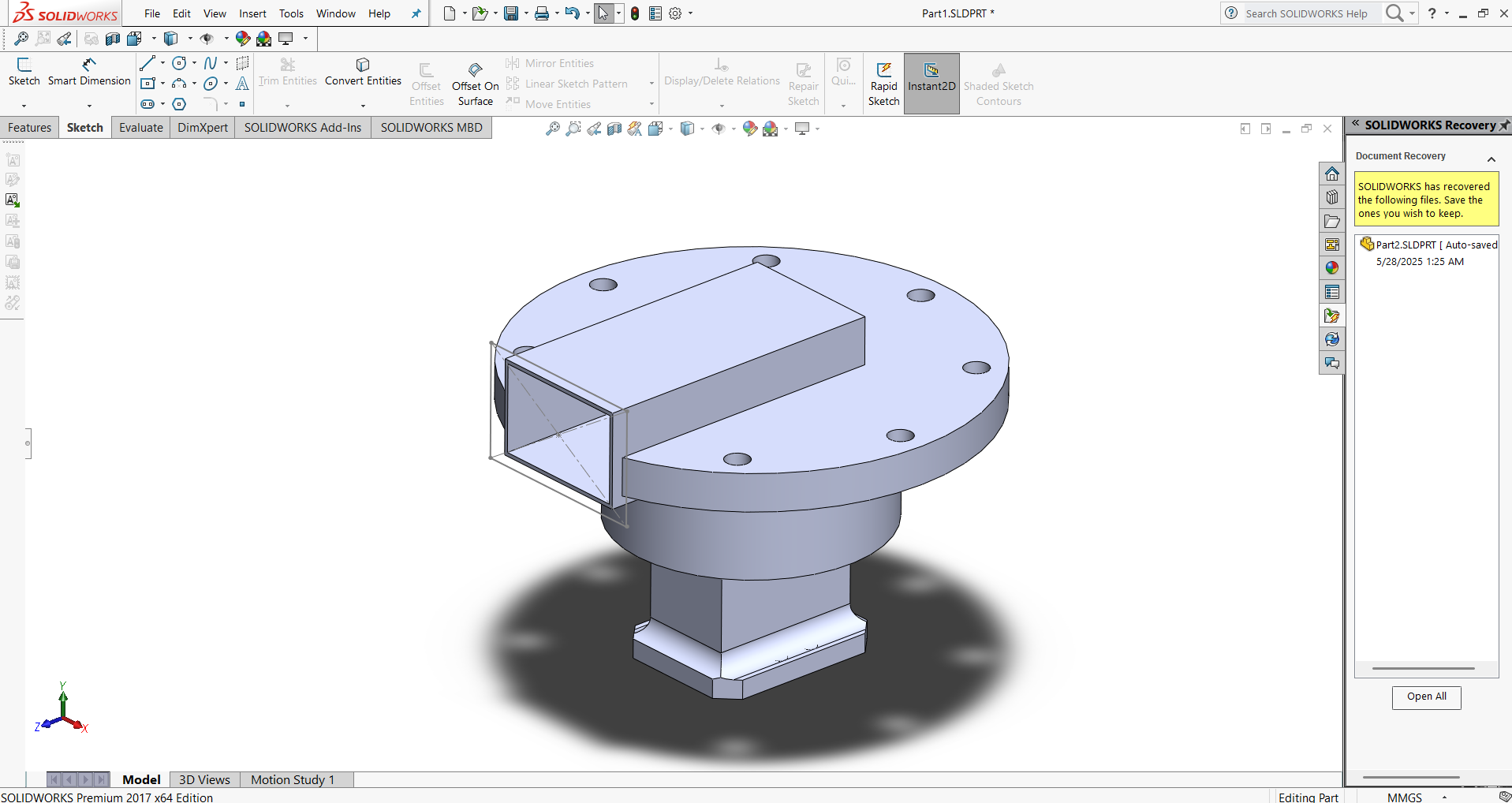
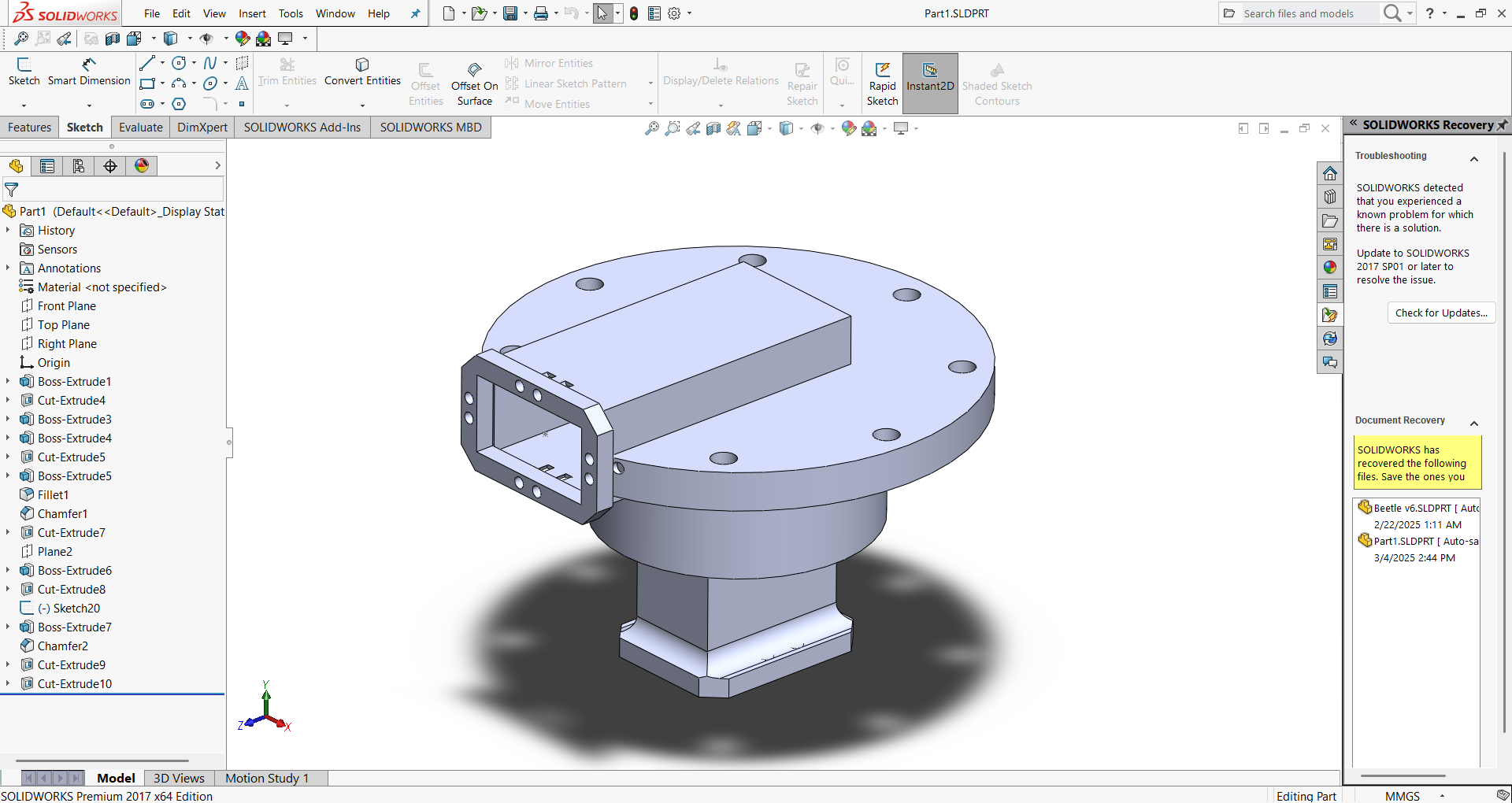
SolidWorks is used in the industrial equipment industry to design and develop machinery, tools, and other equipment. The software helps in creating 3D models of the equipment, simulating its performance, testing for safety and durability, and optimizing its design for efficiency and productivity.

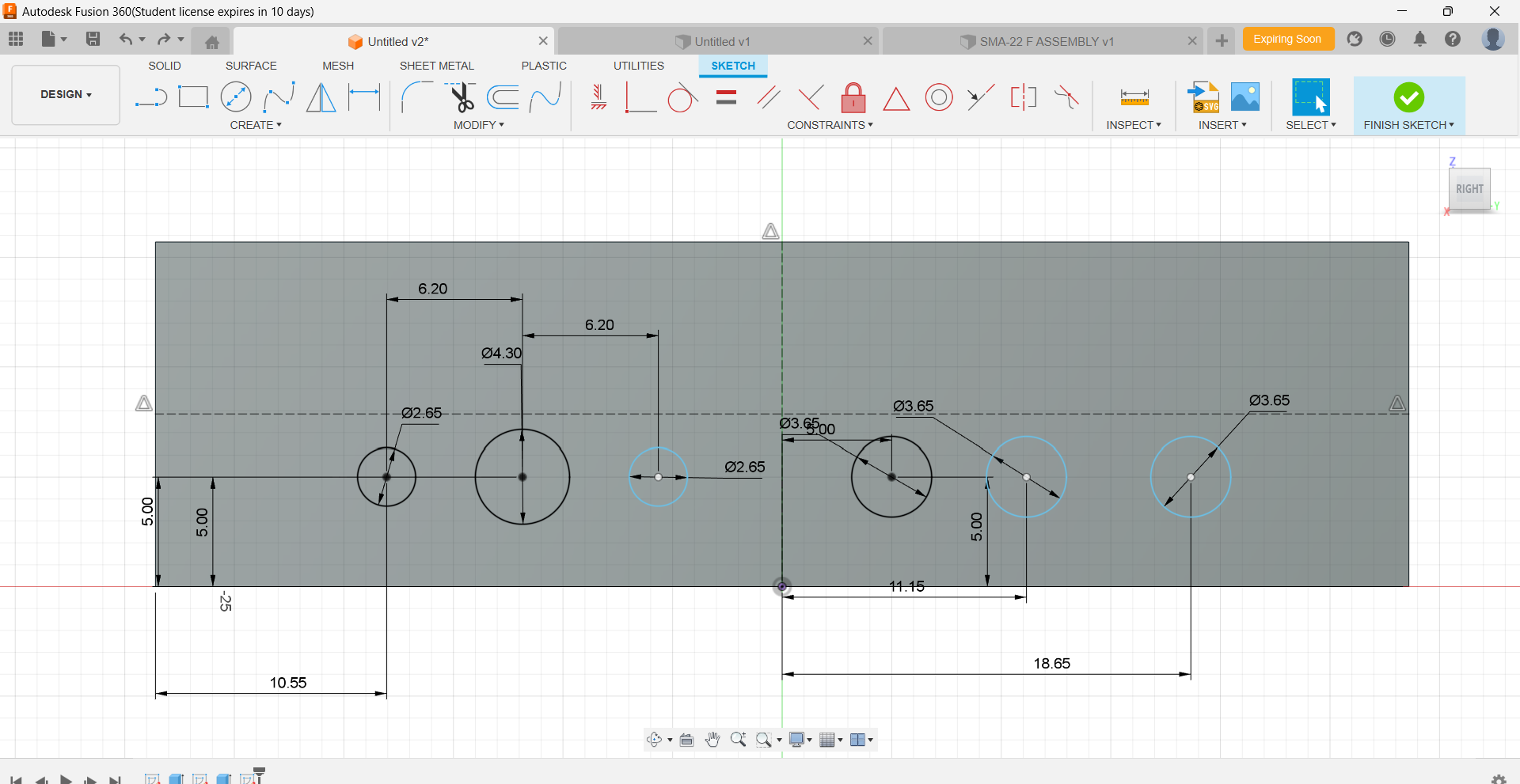
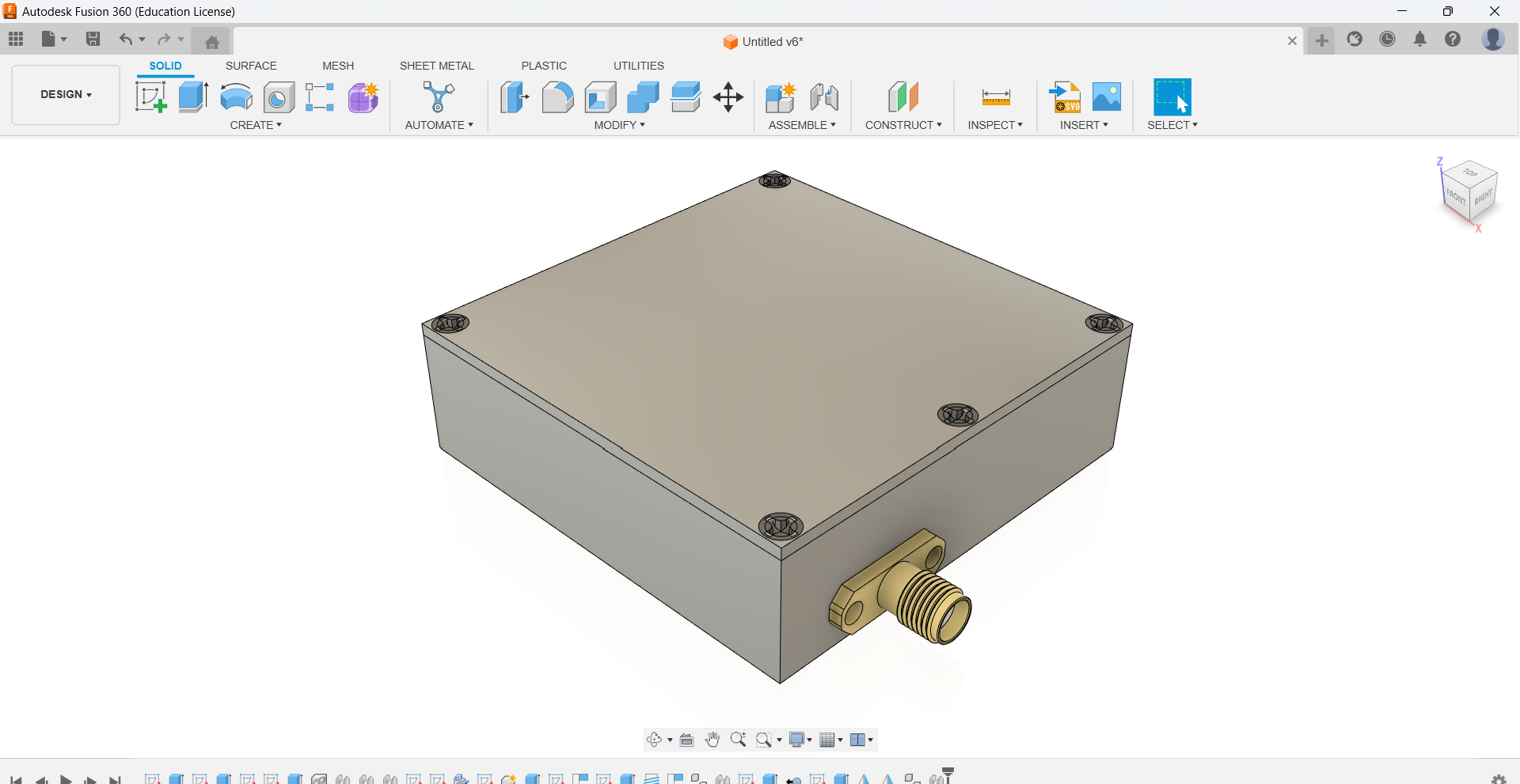
Autodesk Fusion 360 is a cloud-based software application that helps users design, engineer, and manufacture products. It has features for 3D modeling, simulation, and collaboration. 

2.1. SOILDWORKS

SOLIDWORKS is a widely used 3D CAD (Computer-Aided Design) and CAE (Computer-Aided Engineering) software primarily used for designing and engineering products. It helps engineers and designers create precise 3D models and assemblies, supporting the entire product development process from initial design to manufacturing. SOLIDWORKS is known for its parametric design capabilities, allowing users to make changes and see how they affect other parts of the design.

2.2. Process & Steps

    Step 1: Prep & choose a plane
    • Start a new Part, units: mm.
    • In the FeatureManager, select Front Plane → Sketch. You should see the three orthogonal planes (Front/Top/Right).
    • Tool palette and gained an understanding of orthogonal views, which help in accurately visualizing and designing objects from different perspectives.
    2D Design

    Step 2: Sketch the base outline
    • On the Front Plane, use Sketch → Circleand draw a circle from the origin. Add Smart Dimension for the required size.

    2D Design

    Step 3: Add bolt-pattern references & holes (in sketch), then cut
    • Add a second (smaller) construction circle to act as a PCD for holes.

    2D Design

  • Draw one small circle for a hole on that PCD, then use Sketch → Circular Pattern(Equal spacing, 360°, Instances = 6 or 8 as needed) to pattern it around.


  • 2D Design

  • Exit Sketch → Features → Extruded Cut; select the hole circles and set Through All (or a depth > plate thickness) to make the through-holes in the flange.
  • 2D Design

    Step 4.Create the Base Flange + Hub as Solids
    • For the flange disc: with the large outer circle sketch visible, do Features > Extruded Boss/Base to the desired thickness.
    • For the raised hub: sketch a circle on the top face and Extruded Boss/Base it upward to form the center boss. (You end up with a flange + cylindrical hub.)


    2D Design

    Step 5. Build the Tapered Square Boss on the Hub
    • On the hub’s top face, use Sketch > Center Rectangle, add dimensions, then apply Features > Boss-Extrude.
    • To achieve the taper:
      • Enable Draft inside Boss-Extrude and set the required angle, or
      • Extrude a straight prism first, then apply Features > Draft to the four side faces.
    • The result forms a tapered “frustum-like” square boss, seamlessly integrated on top of the cylindrical hub.
    2D Design

    Step 6. Add the Top Pad and Edge Breaks
    • On the tapered boss, sketch a slightly larger square and use Boss-Extrude to create a shallow pad (~5 mm thick).
    • Break the sharp corners using Features > Chamfer (Distance × Distance; e.g., 10 mm on four edges). Fillets can also be applied on other edges if desired.


    2D Design

    Step 7. Finish the Flange Details & Additional Features
    • If more flange holes are needed, place one on the bolt circle and use Features > Circular Pattern to replicate the Cut-Extrude feature around the axis.
    • Additional features shown in the image:
      • Sketch a rectangle on the top face and Boss-Extrude
      • On the front face, sketch a smaller rectangle and Cut-Extrude it to create a hollow section. Then sketch small circles and Cut-Extrude to make the ring of screw holes.
      • Apply Fillet/Chamfer to edges as required for smooth transitions and aesthetics.


    2D Design

    Step 8. Finalize
    • Single Solid Body – Shows the flange assembly as a unified solid body with all bosses and cuts merged. Ensures the design is complete before final touches.


    • 2D Design

    • Final Output & Feature Tree – Displays the complete part with all features, fillets, and chamfers applied. Can also include appearances or shadows for a quick render preview.


    • 2D Design

      2D Design

    • The finalized part is now ready for manufacturing, simulation, or as a completed project submission.


    • 2D Design

    • Step 5: 3D Model


    • 2.3. Challenges & Solutions

      🔹 Challenge: Sketch Over-Defining or Under-Defining

      ✅ Solution:Use the “Display/Delete Relations” tool to identify and fix conflicting constraints. Always start with simple, fully defined sketches and add dimensions systematically.

      🔹 Challenge:Performance Lag in Large Assemblies

      ✅ Solution: Use “Large Assembly Mode,” suppress unnecessary components, and enable lightweight components. Consider using SpeedPak configurations to simplify geometry without losing references.

      🔹 Challenge: Feature Failures Due to Sketch Changes

      ✅ Solution: Use robust design practices like fully defining sketches, avoiding unnecessary external references, and employing design tables or configurations for controlled variations.

      🔹 Challenge:File Compatibility and Version Issues

      ✅ Solution: Always save in backward-compatible formats (e.g., STEP or IGES) when sharing with users on older versions. Use the “Pack and Go” feature to include all dependencies when transferring files.

      🔹 Challenge: Difficulty in Creating Complex Surfaces or Organic Shapes

      ✅ Solution:Leverage the “Surface” tools instead of solid features for complex forms. Use tools like “Boundary Surface,” “Loft,” and “Filled Surface” combined with guide curves for smoother, more controlled geometry.

2.4. FUSION 360

Process & Steps

  • Solid works gave me an experience on how to design and usage of tools. that helped me to understand Fusion 360.
  • Dimentions

  • 2D Design


  • 3D Design

  • 2D Design

    Challenges & Solutions

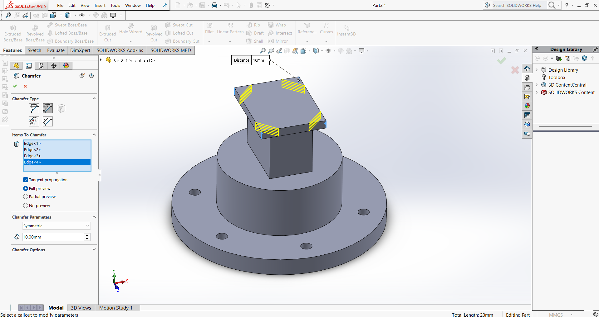
    1️⃣ Understanding the Tool Palette & Features

    🔹 Challenge: Initially, navigating through the tool palette and understanding the functions of different tools in Fusion 360 and SolidWorks was overwhelming.

    ✅ Solution: I followed tutorials, experimented with different tools, and referred to official documentation to understand their applications.

    2️⃣ Difficulty with Orthogonal Views

    🔹 Challenge: Switching between top, front, and side views in orthogonal mode felt confusing, and aligning sketches correctly was tricky.

    ✅ Solution: Practiced by drawing simple objects in multiple views and used the view cube and constraints to align sketches accurately.

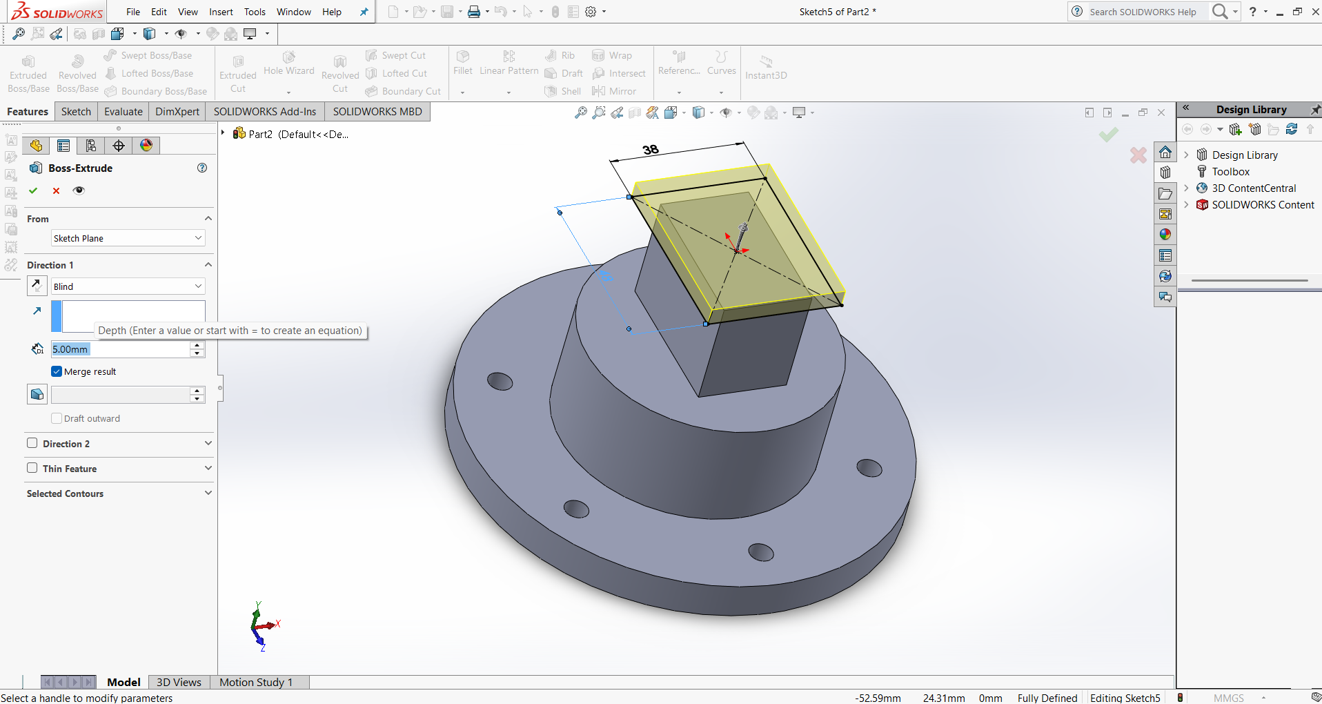
    3️⃣ Struggles with Parametric Design

    🔹 Challenge: Initially, I faced issues in defining constraints and dimensions for parametric modeling, which caused unexpected errors when modifying designs.

    ✅ Solution: I learned to apply constraints systematically, used dimension-driven design, and tested different values to see how the model responded.

    4️⃣ Performance Issues with Complex Models

    🔹 Challenge: When working with detailed 3D models, the software lagged, making it difficult to navigate and edit designs smoothly.

    ✅ Solution: Optimized my workflow by using lightweight preview modes, reducing unnecessary details, and enabling performance settings in the software.

    5️⃣ Exporting & Compatibility Issues

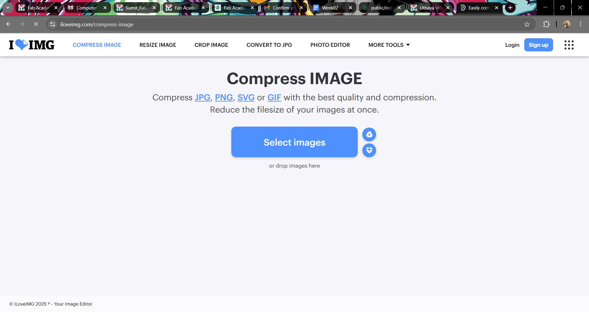
    🔹 Challenge: Exporting files in the right format (DXF, STL, SVG) for fabrication sometimes caused scaling issues.

    ✅ Solution: Double-checked units and scaling settings, tested exports in different software, and ensured proper format selection for the intended use.

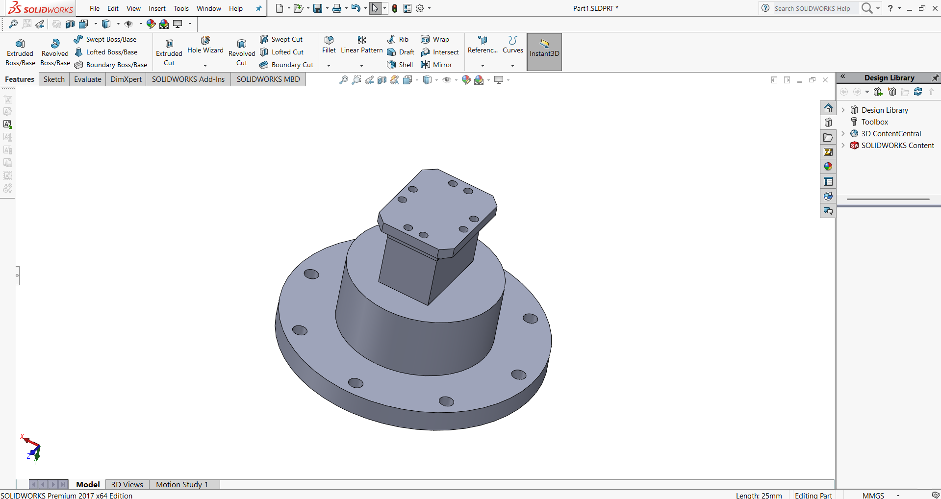
    Each of these challenges helped me develop a structured approach to CAD modeling. With continuous practice, patience, and troubleshooting, I gained confidence in using CAD tools for design and fabrication. 🚀

    How to compress the images

    • By using the I LOVE IMG website I compressed my images upto 50-20 Kb


    • 2D Design

    • After selecting the images which is collectively I filed in one folder, I set the image size and reduce it . Then I delete it from the web server by using the deleted button.

    How to compress the Video

    • By using the VEED website I compressed my videos respective sizes.


    • 2D Design

    • If the Video not compressed into expected size then repeat the process often then it will get reduce that size.

    The end of week 2

    Fab Academy is an intensive five-month program that teaches students to envision, design and prototype projects using digital fabrication tools and machines. It is a multi-disciplinary and hands-on learning experience that empowers students to learn-by-doing and inspires them to make stuff locally to become active participants in sustainable cities and communities.

    Get In Touch

    Rathinam nagar,Theni(Dt)-625531, Tamil Nadu, INDIA

    +91 8122997014

    uthayavelraj@gmail.com

    Visitors Counter freevisitorcounters's Website

    Copyright @2025 © Uthaya Velraj. All Rights Reserved.

    Source code hosted at GitLab

    Source code hosted at GitLab