Final Fabrication
Back
2025 FABLAB
Due to the 3D printer issues I stuck to finish my final project and then as per my instructor suggestion I made up on mind to demonstrate my model in cardboard.
So I planned to use the Pepakura software to do the cardboard modeling
Pepakura
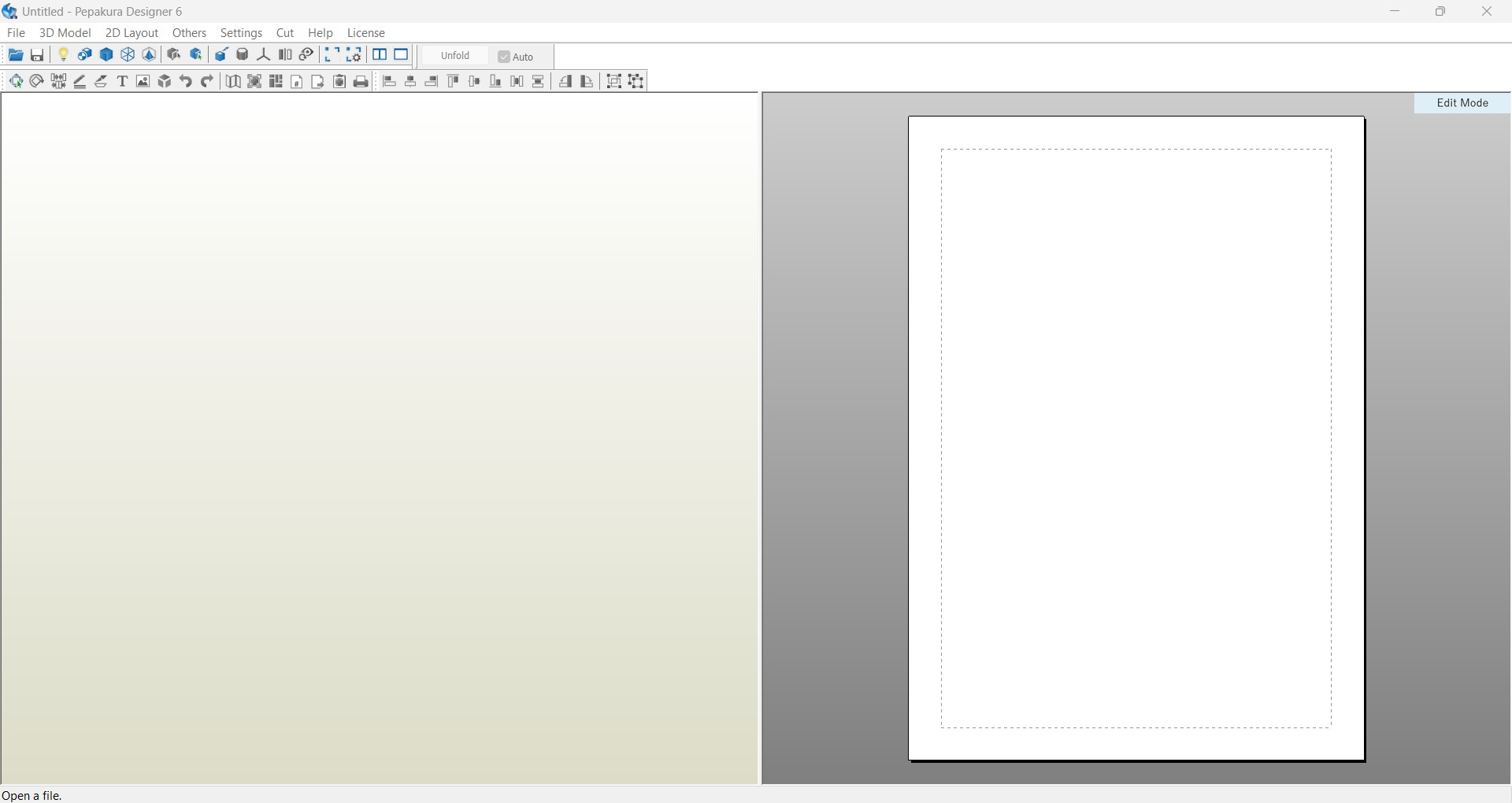
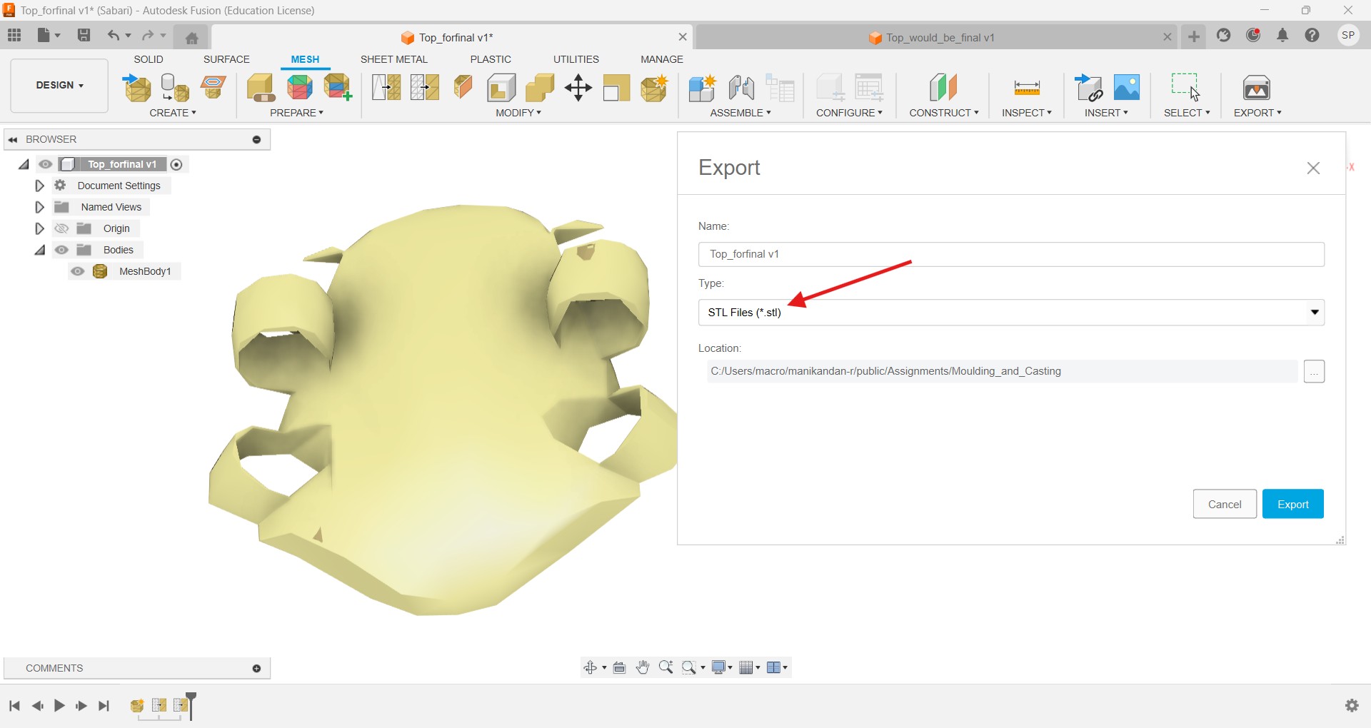
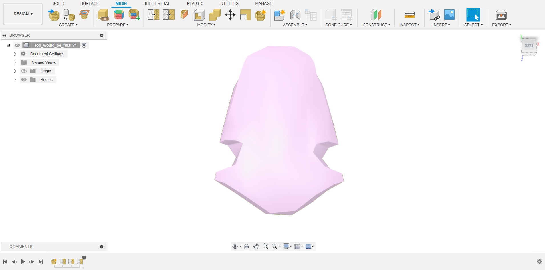
I take my drone parts out into STL format and upload it to the Pepakura software but it seems like its mesh is too high to do the activity.
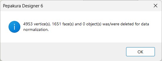
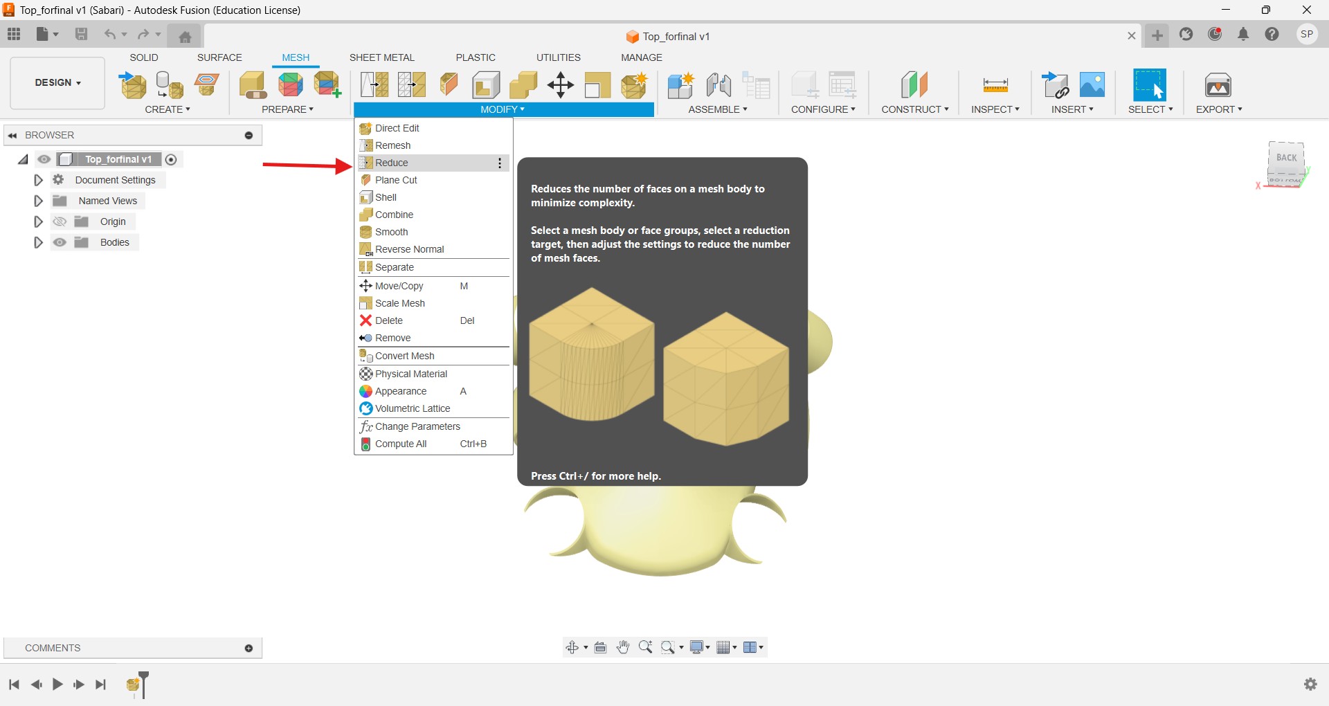
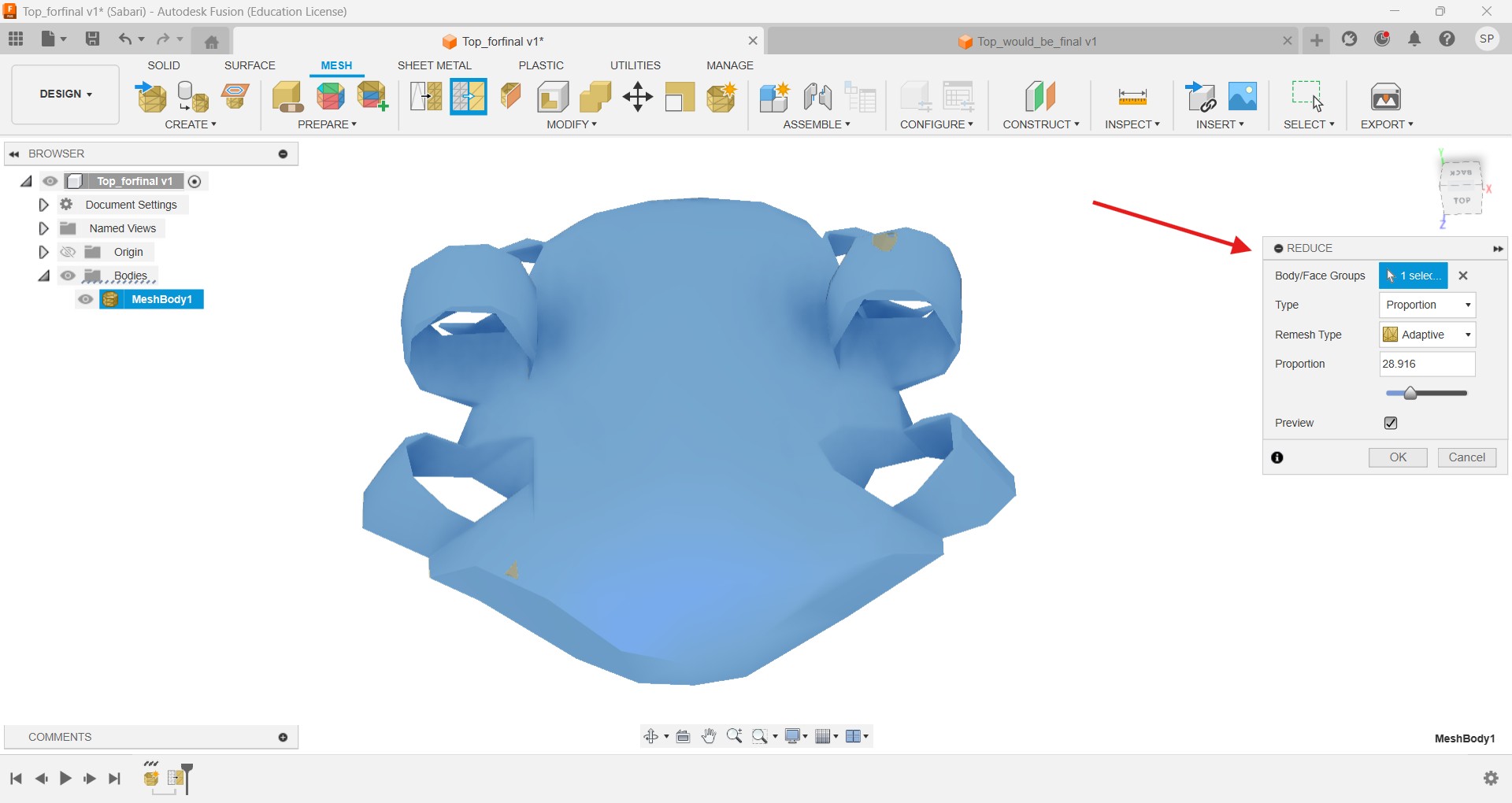
So I should reduce the meshes before I start working, therefore I uses the Fusion mesh part to refine it.
After importing the STL file into the fusion I open the mesh space to do the meshing operation.
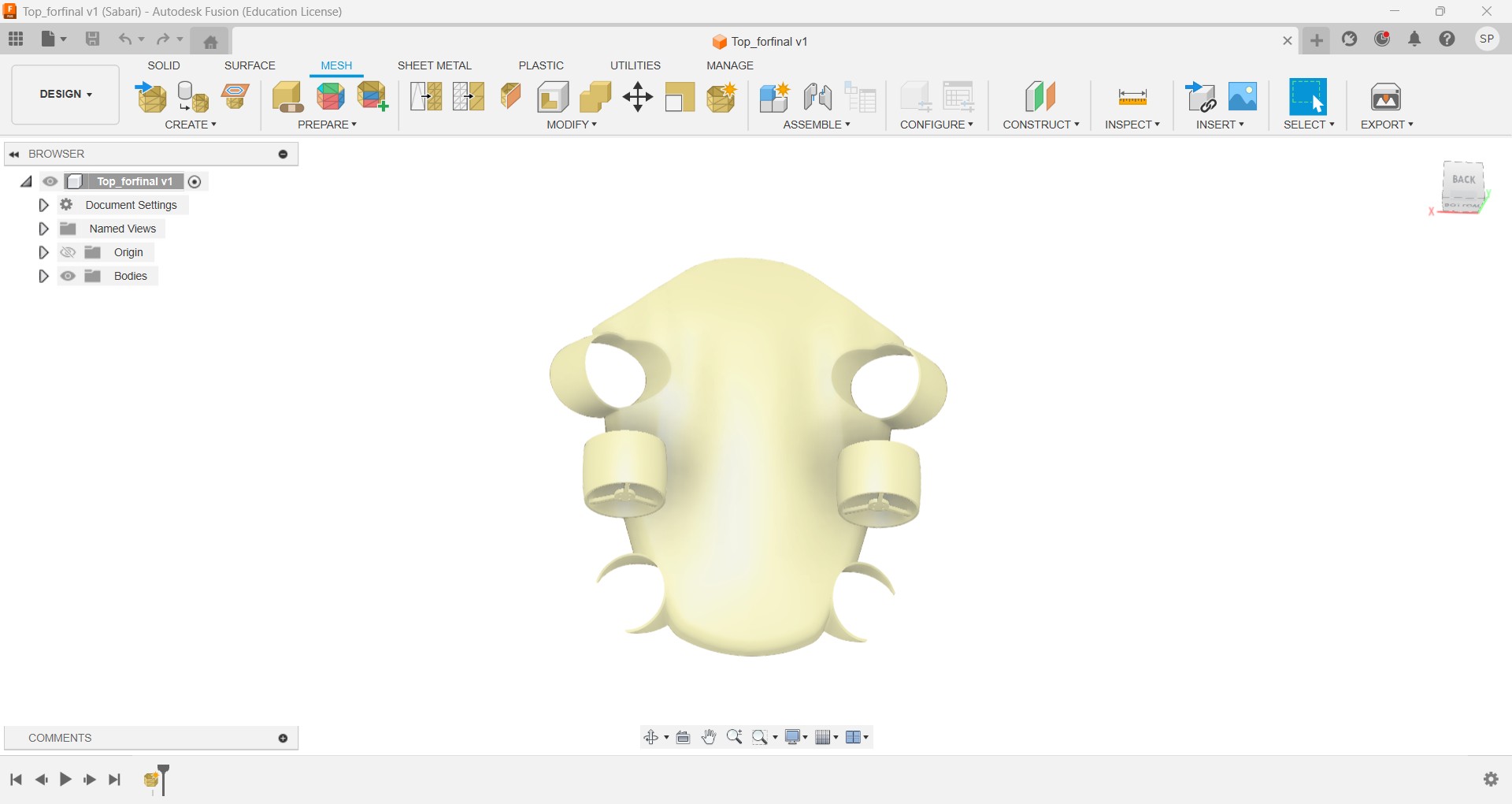
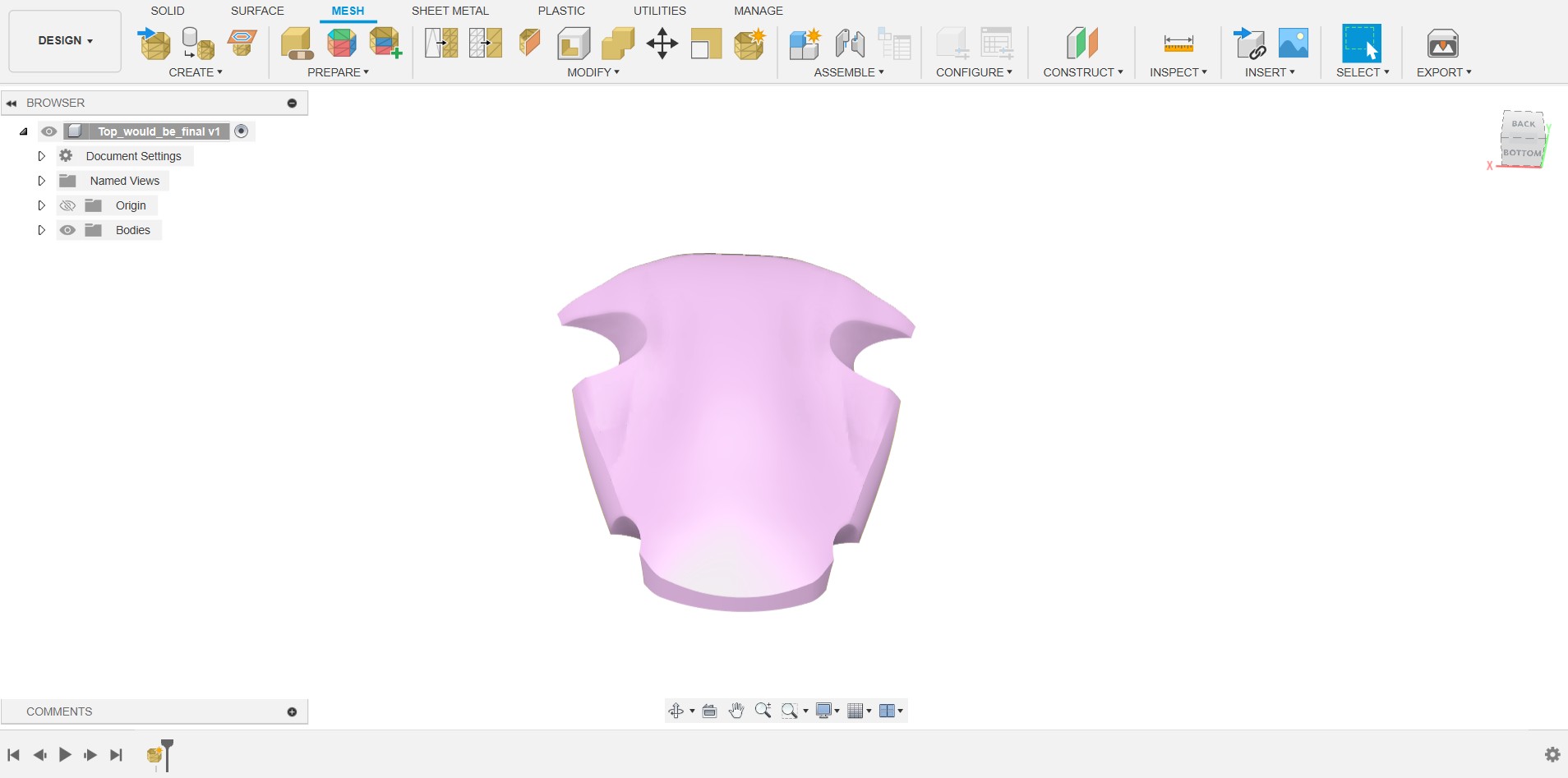
Instead of the whole body I again try to minimize the design setup for pepacura, so took out the motor hubs from the design and did the same steps.
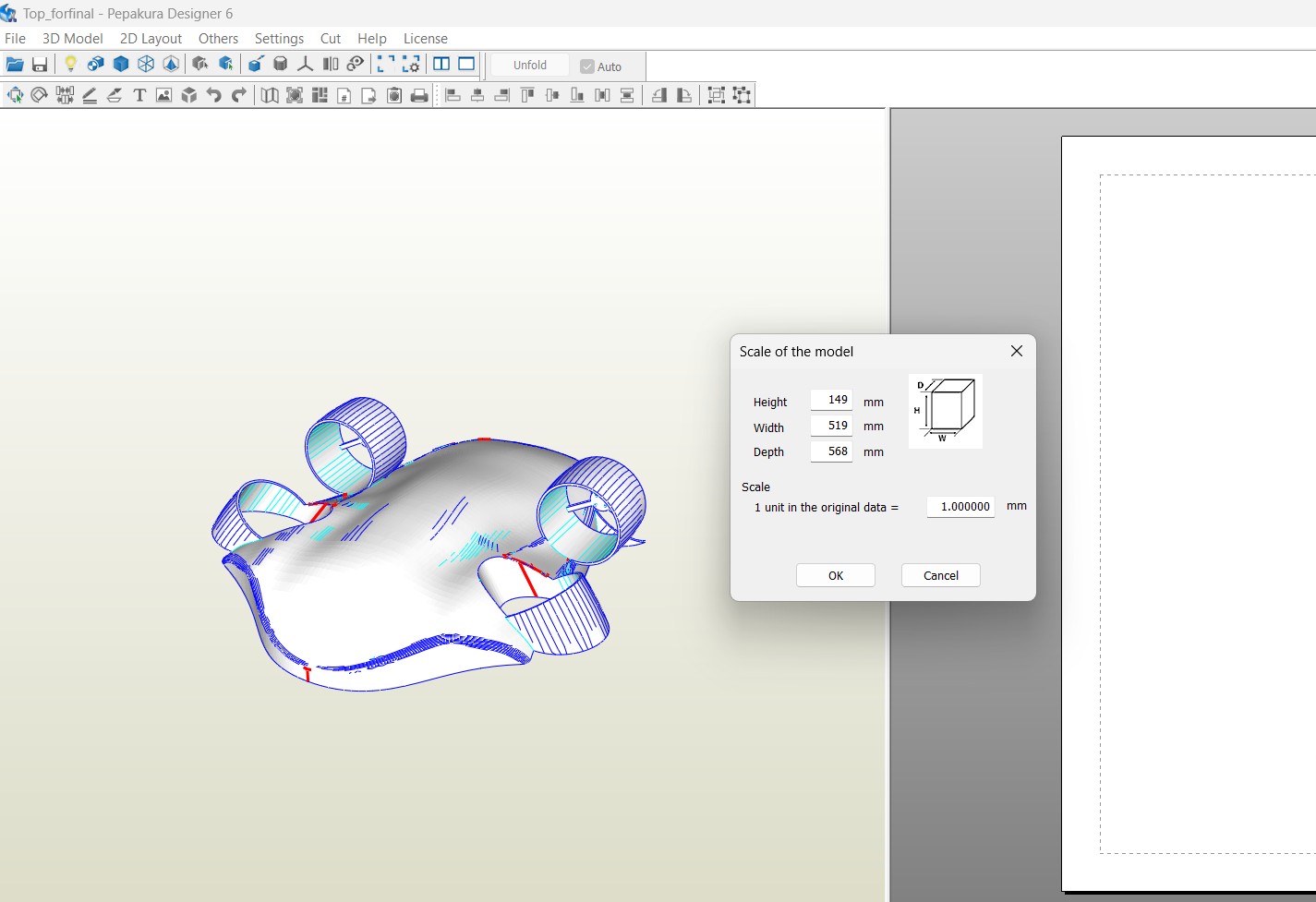
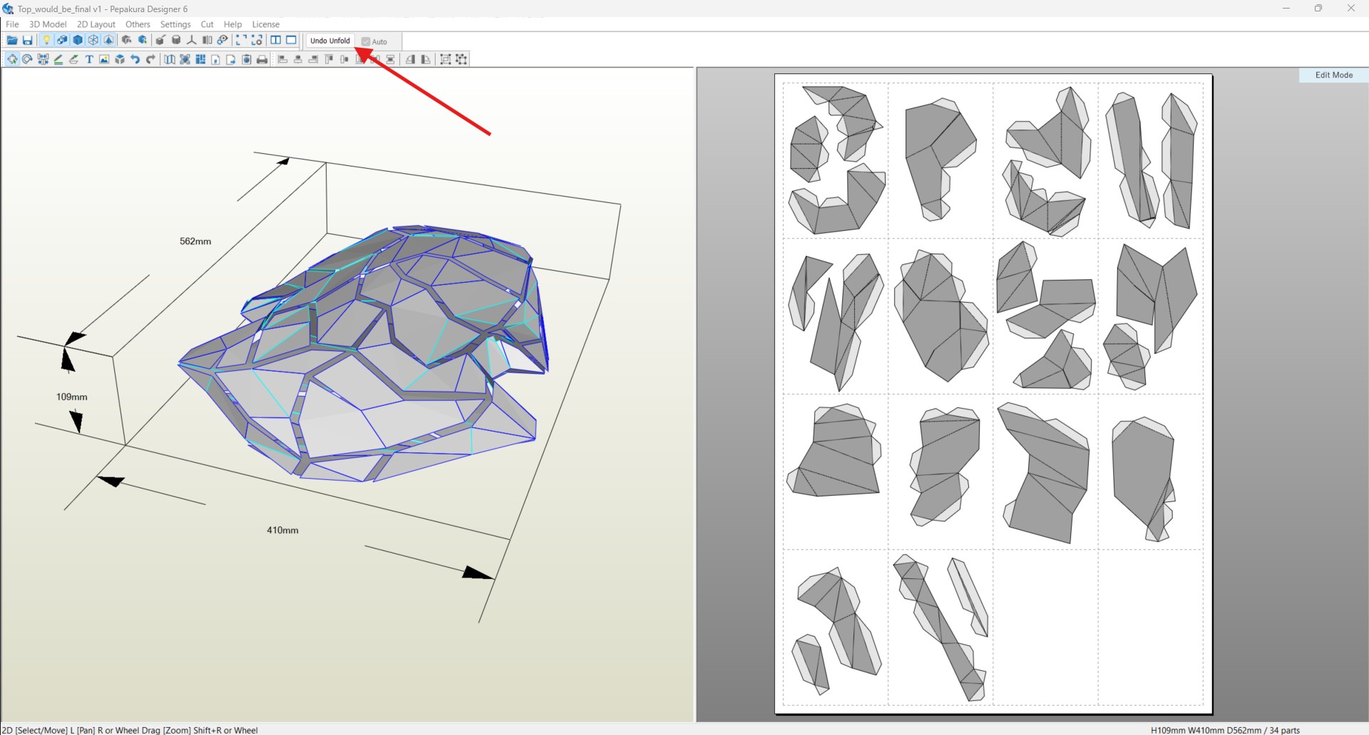
Then Open the Papekura software and import the file and unfold the sheet and properly arrange the unfolded parts into the limited dimensions for the further process
In every sheet dimension is A4 sheet size we can also chage the sheet size whatever we want, but I default choose the A4 sheet.
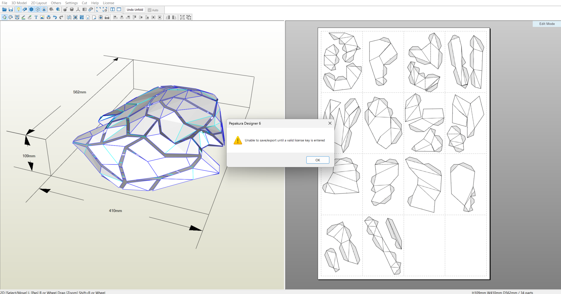
In pepakura we have the limited options, after the edit I can’t able to save it, so instead of that we can only take our work as output. In Files there is an export obtion available in PDF format so I choose it (short key - ctrl+shift+P)
Fabrication
After the pepakura design I take out the PDF for the carboard process, I take the print in our printer on A4 sheets
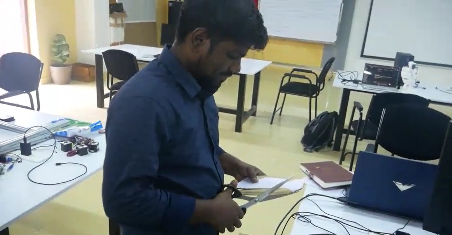
Then I cut all the designs carefully regarding their shapes
Then Stick on the empty cardboard to stick it together
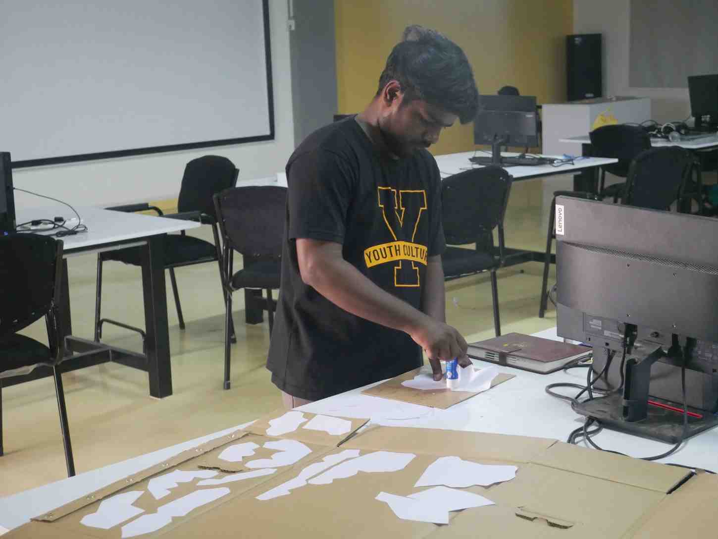
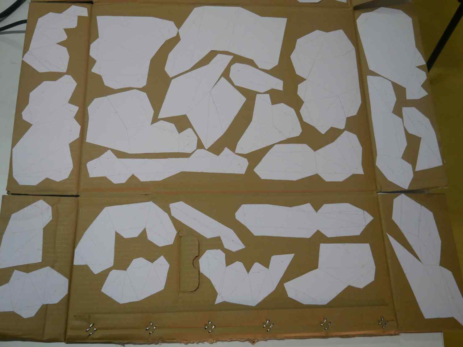
After stick all the papers into the cardboard I start cutting one by one
Finally I cut out all the parts and start the assembling, in the paper w can see the numbers that indicate where it will be stick with their next side pieces.
We can also will see there is some lines which is the reference lines to do the bending to stick on the others more suitably. So I little bit cut down that lines to bend it easily.
By using the 743 glue I start the fabrication work to attach the parts together
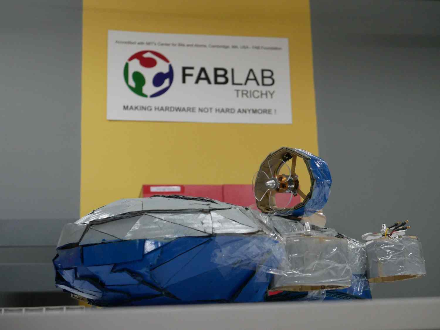
Then I barely created the top part of my drone and painting it after peel out the A4 sheets which is I stick above it
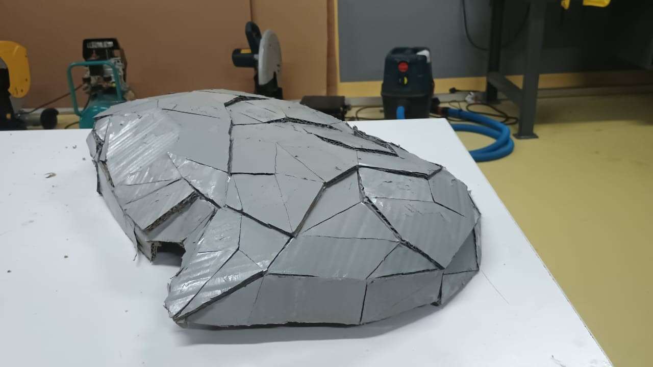
Just like this repeat the same process for the bottom part and did it, also painting it completely
2026 FABLAB
Assembly of the Drone Structure and Motor Hubs
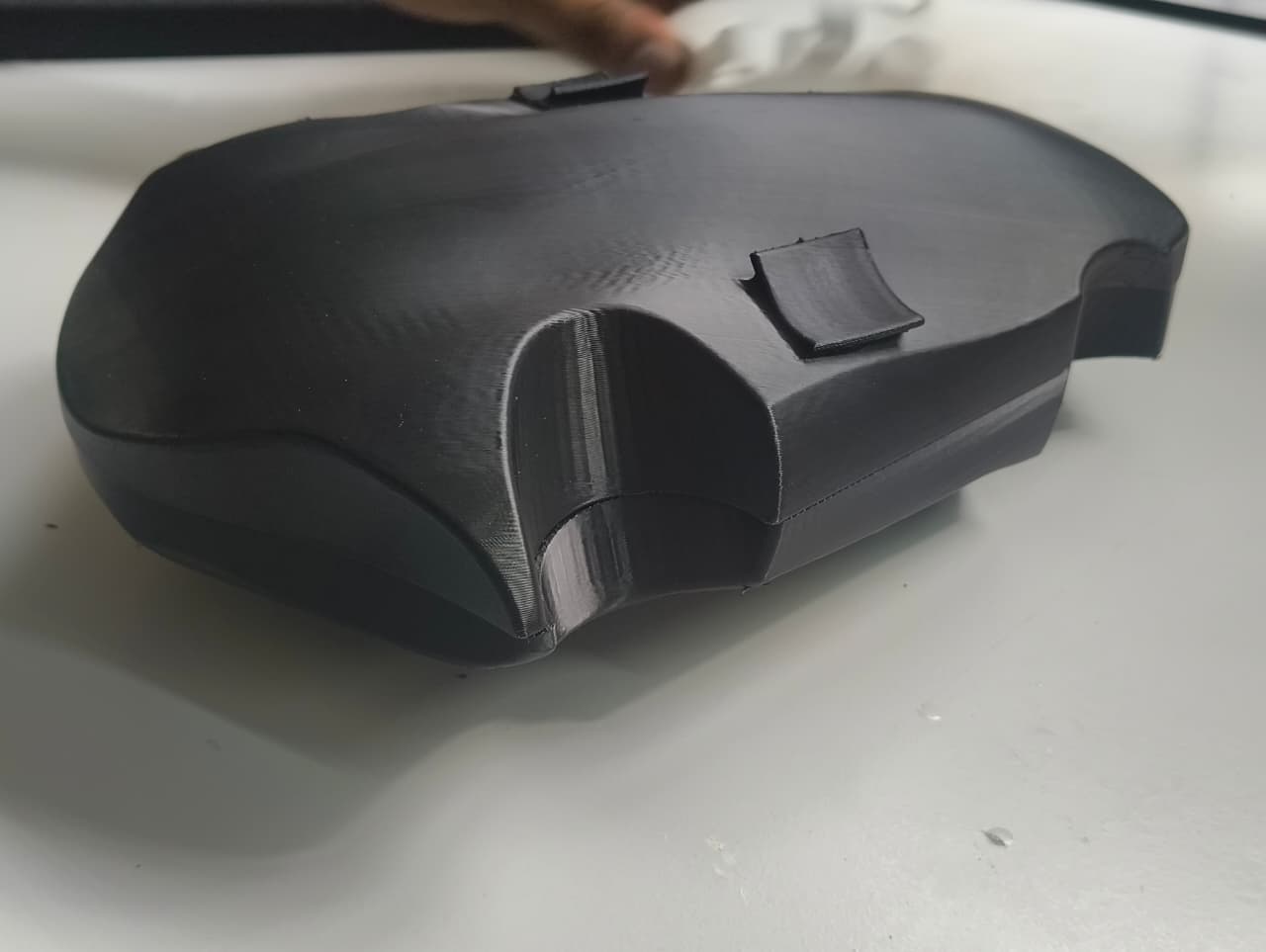
After completing the fabrication of all structural components, I began the assembly process by verifying the fit between the top and bottom sections of the drone. The two parts were aligned and fastened together using the bolt holes that had been incorporated during the design stage.
The bolts were inserted and tightened to evaluate the dimensional accuracy of the printed components and the overall assembly fit. The top and bottom sections aligned correctly, and the fasteners engaged smoothly without requiring any additional modifications. No significant defects or misalignments were observed during the assembly process.
Motor Hub Preparation
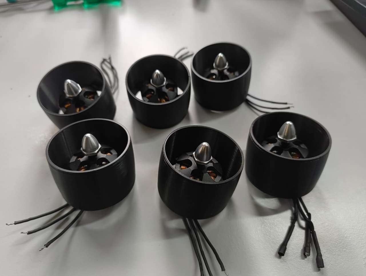
Once the main body assembly was validated, I proceeded with the preparation of the motor hubs. To enable electrical connections between the motors and the internal electronics compartment, wire-routing holes were created in each motor hub using a drilling tool.
After drilling the required openings, the brushless motors were installed into their respective motor hubs. The fit between the motor mounting interface and the motor body was verified to ensure proper positioning and secure attachment.
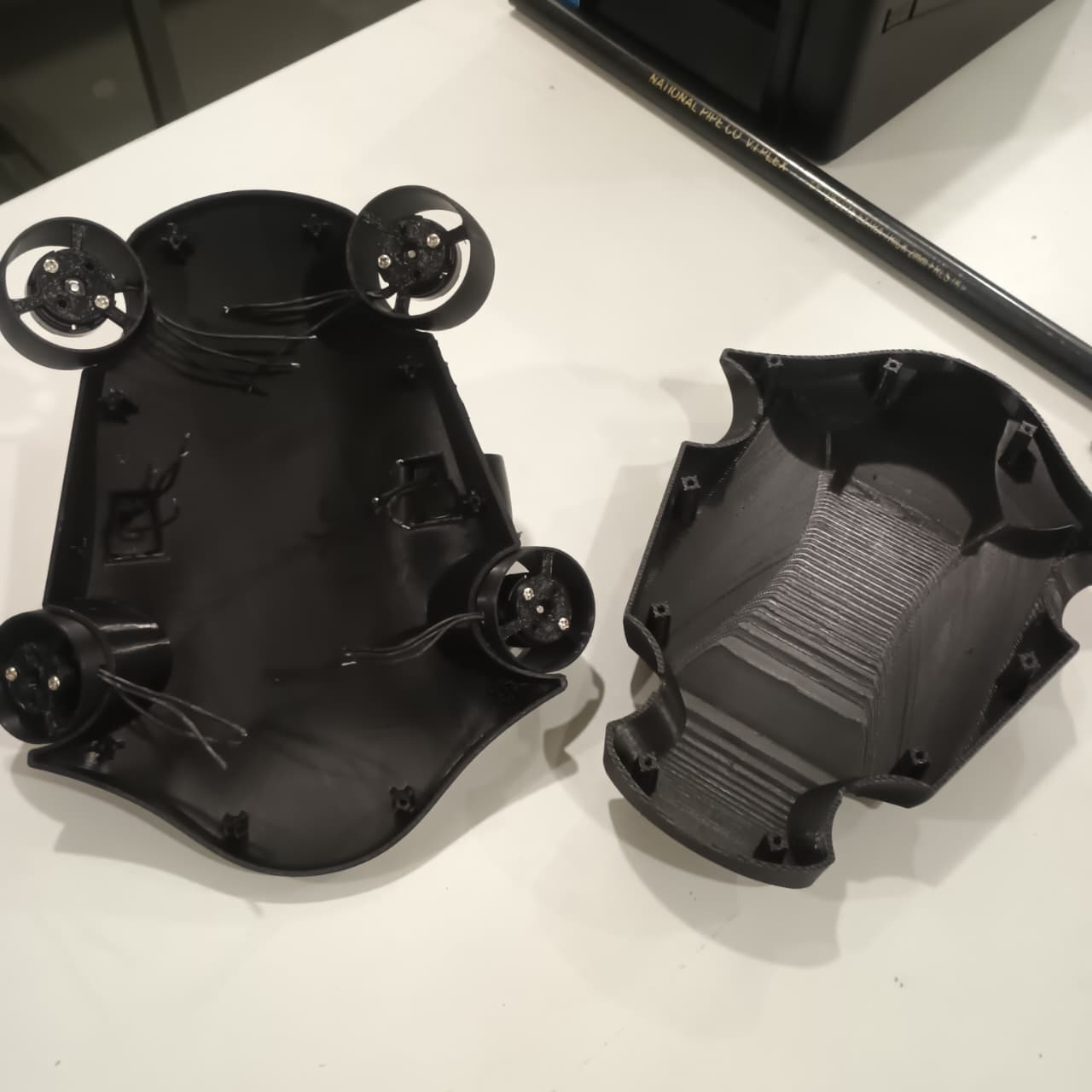
Additional wire-routing holes were then created in the top section of the drone body. These openings were positioned according to the design layout so that the motor wires could be routed from the external motor assemblies into the internal electronics compartment.
Motor Hub Installation
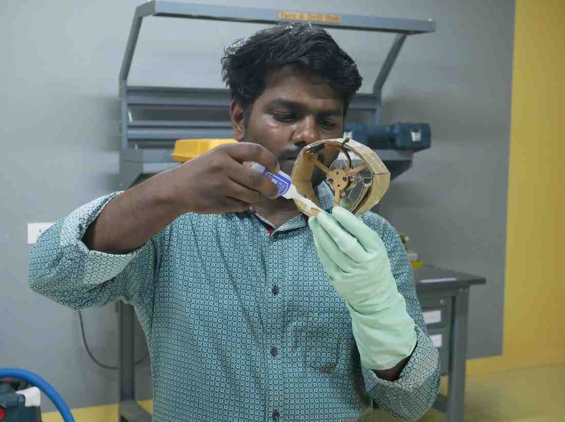
After completing all drilling operations, the motor hubs were positioned in their designated locations on the drone body. The placement was verified against the original design to ensure proper alignment and orientation.
To secure the motor hubs to the drone structure, 743 adhesive was used as a temporary assembly solution for the proof-of-concept prototype. This approach provided sufficient bonding strength for demonstrating the design concept and validating the mechanical integration of the system.
For a production-ready version of the underwater drone, the motor hub attachment method would likely be redesigned using more robust manufacturing techniques and improved finishing processes to achieve greater reliability, serviceability, and long-term durability.
Preparation for Electronics Integration
Once all motor hubs were successfully installed and secured to the drone body, the mechanical assembly stage was completed. The next step involved integrating the electronic components inside the drone enclosure and preparing the system for electrical wiring and functional testing.
The first step was to determine suitable locations for the Electronic Speed Controllers (ESCs) within the drone body while ensuring sufficient space for wiring and future maintenance.
Motor and ESC Wiring
Once the ESC positions were finalized, the motor wires were soldered to their respective ESCs. Care was taken to create reliable solder joints that could withstand handling during assembly and testing.
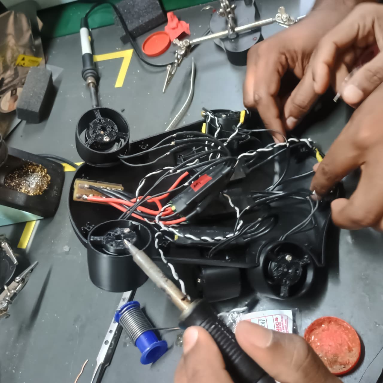
After completing the soldering process, continuity tests were performed to verify that all electrical connections were correct and that no unintended short circuits were present. The power distribution system was also checked using the battery to confirm that the required supply voltage was reaching the electronic components properly.
The electrical inspection confirmed that the wiring and power connections were functioning as expected, allowing the assembly process to continue.
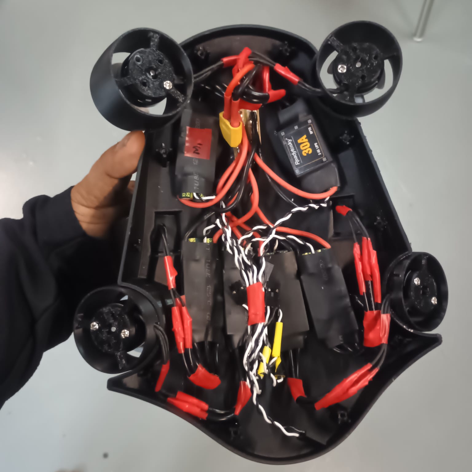
ESC Installation and Wire Management
Following the successful electrical verification, the ESCs were mounted inside the drone body using double-sided adhesive tape. This provided an initial method of securing the components while allowing their positions to be adjusted if necessary.
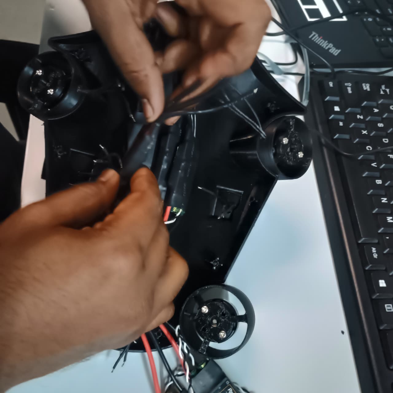
The motor and power cables were then routed carefully through the drone body according to the planned wiring layout. Proper wire management helped reduce clutter within the enclosure and simplified the overall assembly.
To provide additional mechanical security, hot glue was applied around the ESCs and selected wire-routing locations using a glue gun. This helped prevent the components from shifting during handling, transportation, and prototype testing.
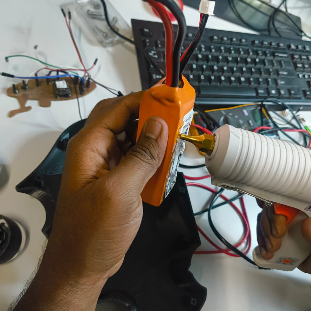
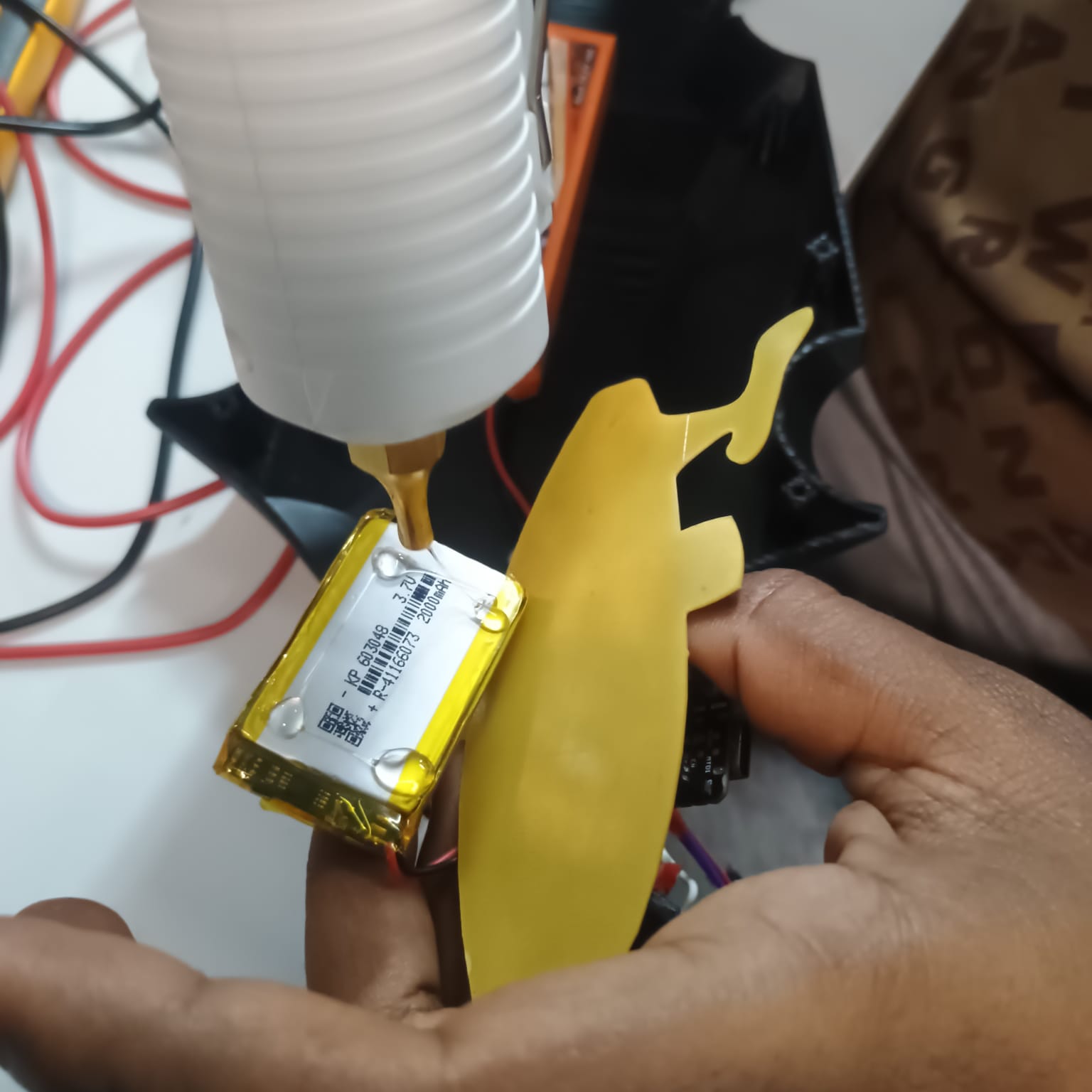
Battery and PCB Installation
After securing the ESCs, the battery and control PCB were installed inside the lower section of the drone body. Their positions were selected to optimize space utilization and maintain a balanced internal layout.
Hot glue was used to temporarily secure these components in place, providing sufficient holding strength for the proof-of-concept prototype while keeping the assembly process simple and efficient.
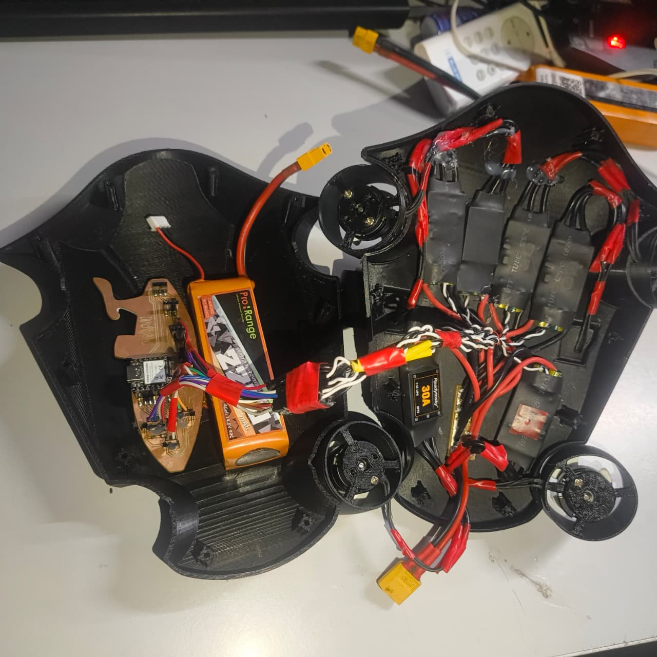
Final Enclosure Assembly
Once all electronic components had been installed and secured, the top and bottom sections of the drone were brought together to complete the assembly. The enclosure was closed and fastened using the designed fastening system to create a compact and integrated prototype.

At this stage, the underwater drone prototype consisted of the assembled mechanical structure, installed propulsion system, integrated electronics, power distribution components, battery system, and control PCB, making it ready for functional testing and demonstration.
QR Code Integration for Project Demonstration
To improve the accessibility of my project demonstration, I decided to integrate a QR code directly onto the top of underwater drone. The purpose of the QR code was to provide quick access to the testing and demonstration page so that visitors could easily understand the functionality of the drone, even when I am unavailable at that time to explain the project.
Instead of printing the QR code on a paper sticker, I explored a more durable and visually appealing solution by fabricating the QR code using an acrylic sheet.
QR Code Generation
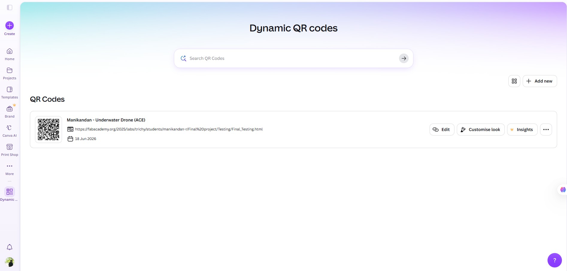
The QR code was first created using Canva and linked to the testing page of the project. Once generated, the QR code was exported as a PNG image file for further processing.

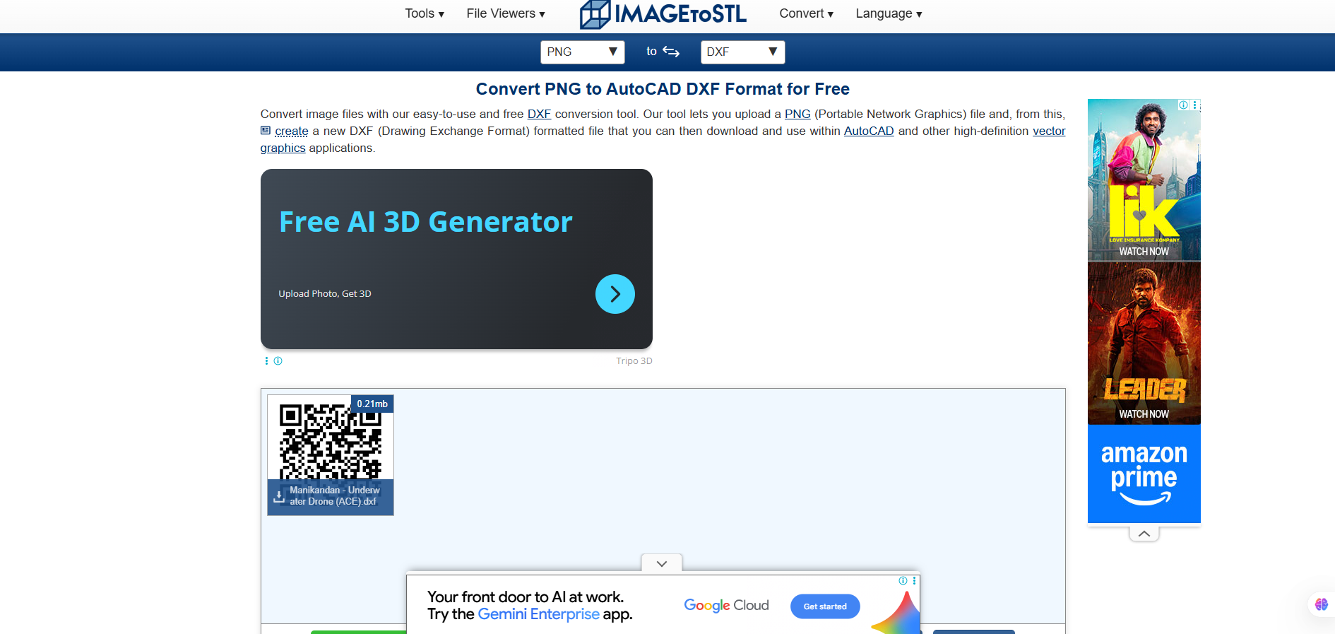
To prepare the design for laser engraving, the PNG image was converted into a DXF file using an online image-to-DXF conversion tool. The DXF format allowed the design to be imported into the laser cutting workflow.
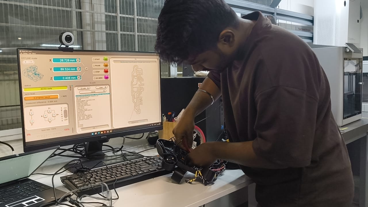
Laser Engraving Process
After converting the file, the DXF was imported into LaserCAD software. The dimensions of the QR code were adjusted according to the available mounting space on the drone body.
The laser engraving parameters, including speed and power settings, were configured based on the acrylic material being used. Several test attempts were carried out to optimize the engraving quality and ensure that the QR code could be scanned reliably.
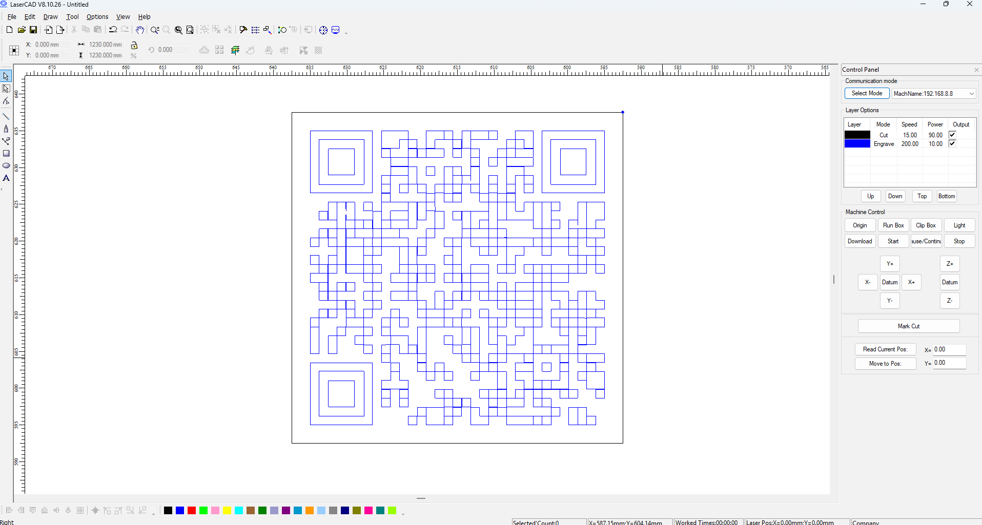
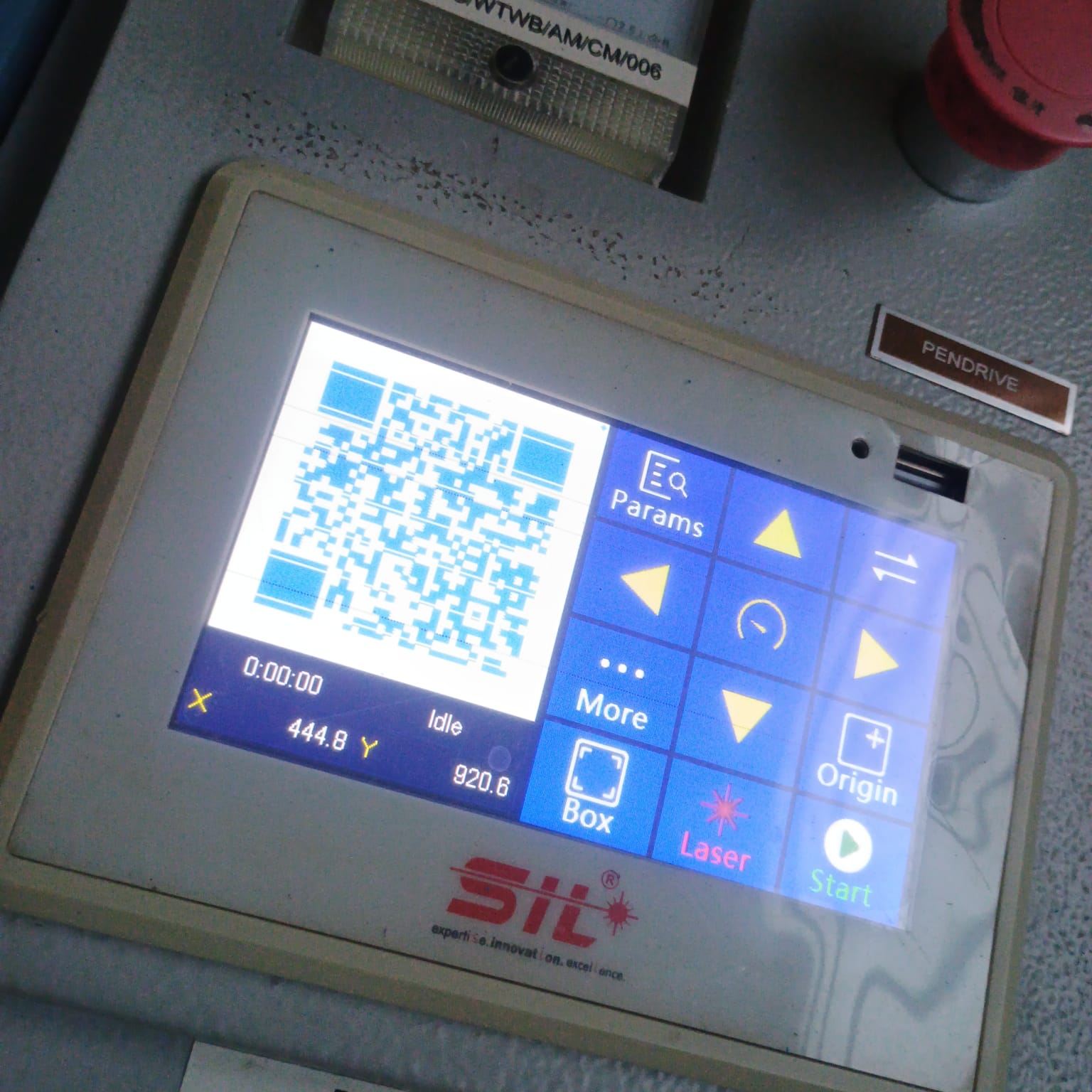
After multiple iterations and parameter adjustments, a clear and readable QR code was successfully engraved onto the acrylic sheet. Parameter I used for engraving in our machine
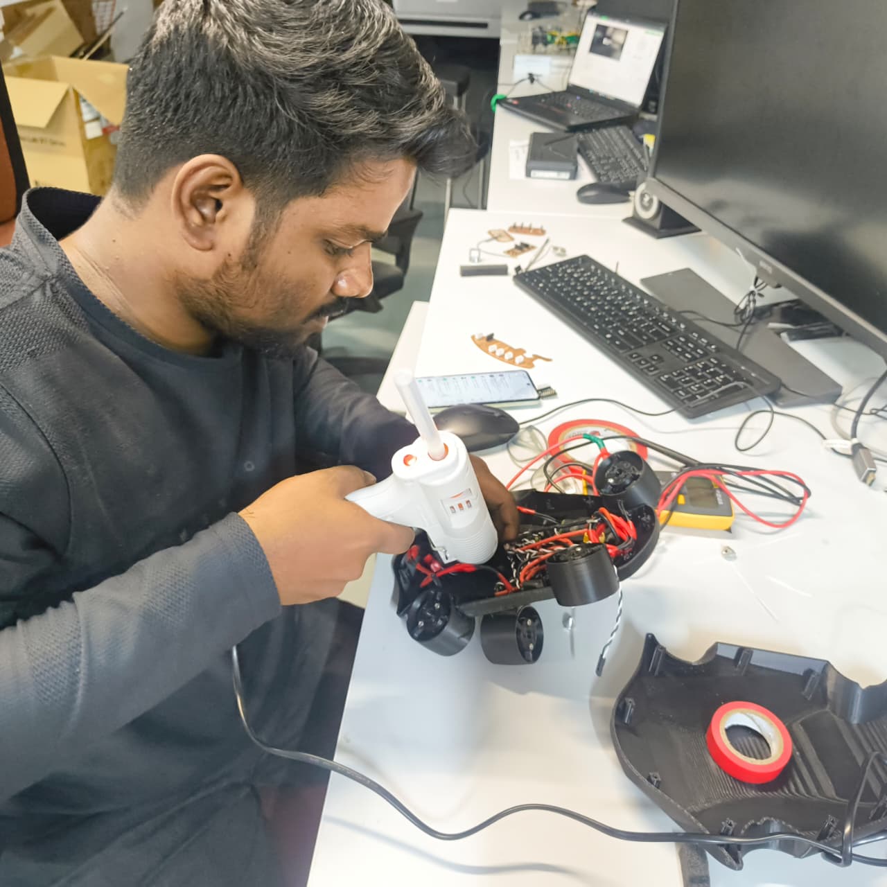
Forming the Acrylic to Match the Drone Surface
The initial plan was to mount the engraved QR code on the rear section of the drone. However, during installation, I observed that the selected mounting area had a curved surface, while the engraved acrylic sheet was flat.
To solve this issue, I decided to thermoform the acrylic so that it would match the curvature of the drone body. A heat gun was used to gradually heat the acrylic sheet until it became flexible.
Once the material softened, it was carefully positioned against the surface of the drone and held firmly in place. As the acrylic cooled, it retained the curved shape that matched the contour of the drone body.
Final Installation
After confirming the fit of the curved acrylic piece, adhesive was applied to secure the engraved QR code onto the drone. The QR code became a permanent part of the prototype and provided an easy way for visitors to access demonstration of dorne working.