Final 3D Printing
Back
2025 FABLAB
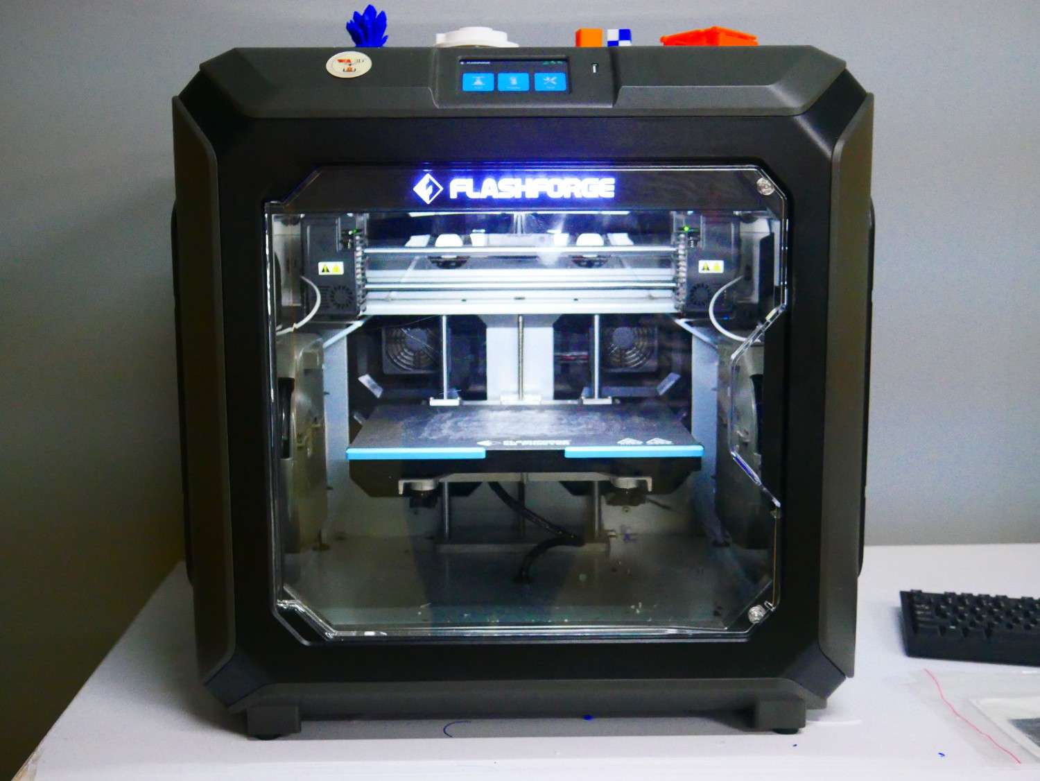
Flash forge
FlashForge is a 3D printer brand known for producing reliable and affordable desktop FDM and resin printers. Popular models include the Creator Pro, Adventurer, and Guider series.
In our lab we have Creator 3 Pro 3D Printer
Specification
| Print Size (L x W x H) (mm) | 300 x 250 x 200 |
| Machine Size (mm) | 627 x 485 x 615 |
| Printing Speed (mm/s) | 10-150 |
| Extruder Type | IDEX (Independent dual extruders) |
| Printing Precision | ±0.2mm |
| Nozzle Diameter (mm) | 0.4mm(0.6/0.8mm) |
| Screen Type | 4.3-inch |
| Extruder Temperature (°C) | 320 |
| Heatbed Temperature (°C) | 120 |
| Filament Compatibility | ABS, ASA, HIPS, PA, PACF, PC, PETG, PLA, PVA, WOOD |
| Data Transmission Method | USB/Wi-Fi/Ethernet |
Pre-Processing
I splited the top 8 parts and 6 bottom parts individually , so totally 14 parts because of the space constraints in that printer. Further I did some changes in my design to split those.
After that I export all 14 parts into STL file format to do the slicing process
Flash Print 5
FlashPrint 5 is FlashForge’s updated slicing software for their FDM 3D printers. Features include model editing, auto-repair, and custom image-based reliefs. Users can preview print paths and adjust parameters in real time. It supports PLA, ABS, PETG, and more.
I used the flash print software for my slicing process
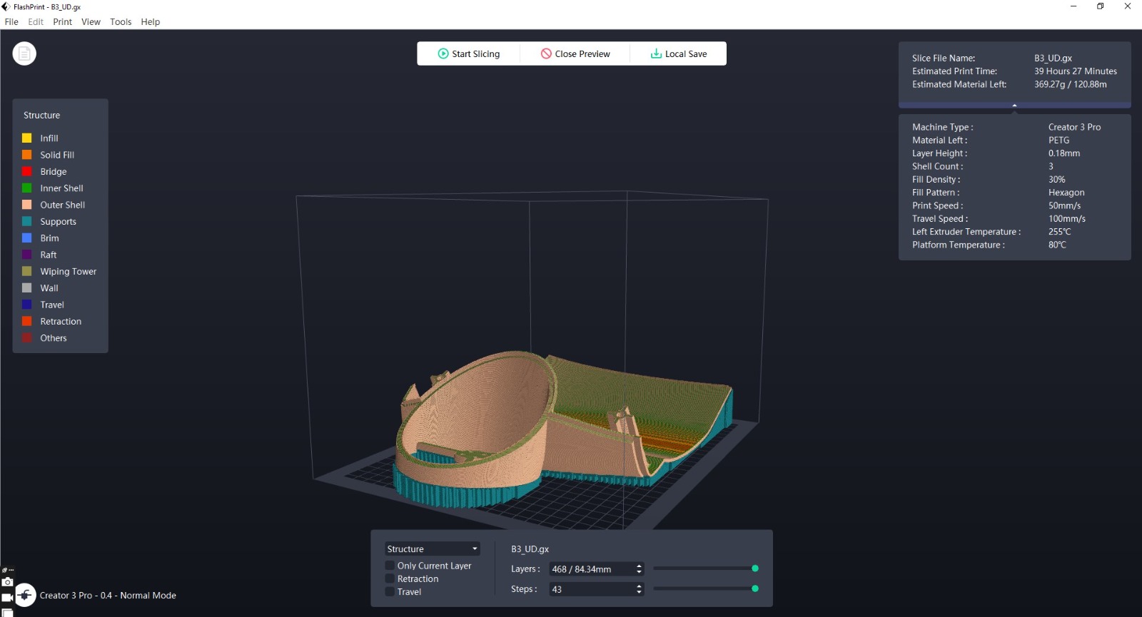
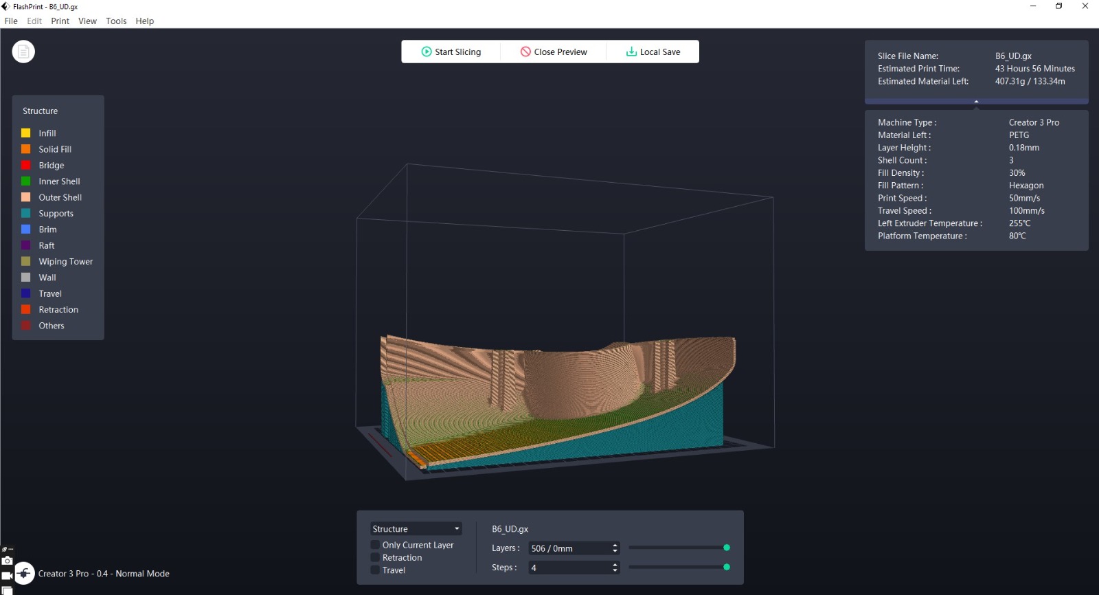
I import the file into the Flashprint 5 software one by one to slicing it. At first I load the top parts into the software
I placed my parts with the good positioning orientation for the optimised surface finish and to reduce the support layer consumption.
Slicing
For printing the parts we need to extract it as STL format
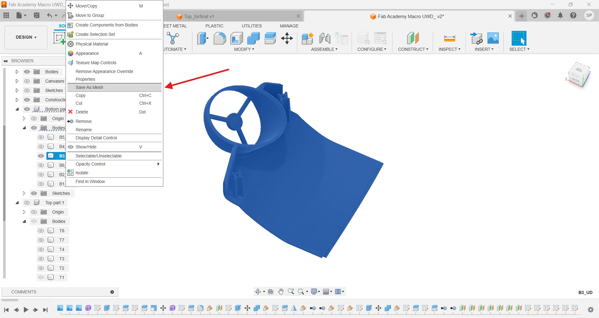
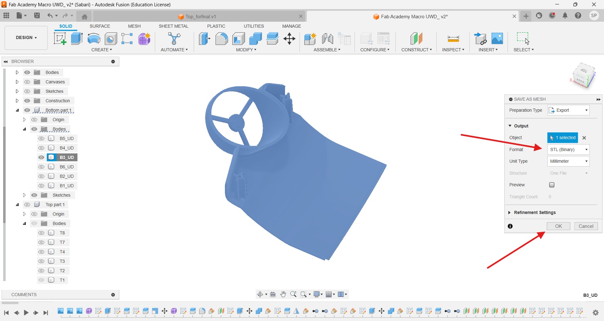
Like this I take out all 14 parts into STL file. Then I used the Flash print software to slicing my desing to convert into gcode
I set the PETG filament to do the printing in the 3D printer
More or less I need 2kg PETG to complete the printing process
I placed my parts in Flash print software with the good positioning orientation for the optimised surface finish and structural integrity.
Printing
After slicing all the parts I start the printing process, I take the copy of gcode from the creality software and import it into the printer.
Challenges
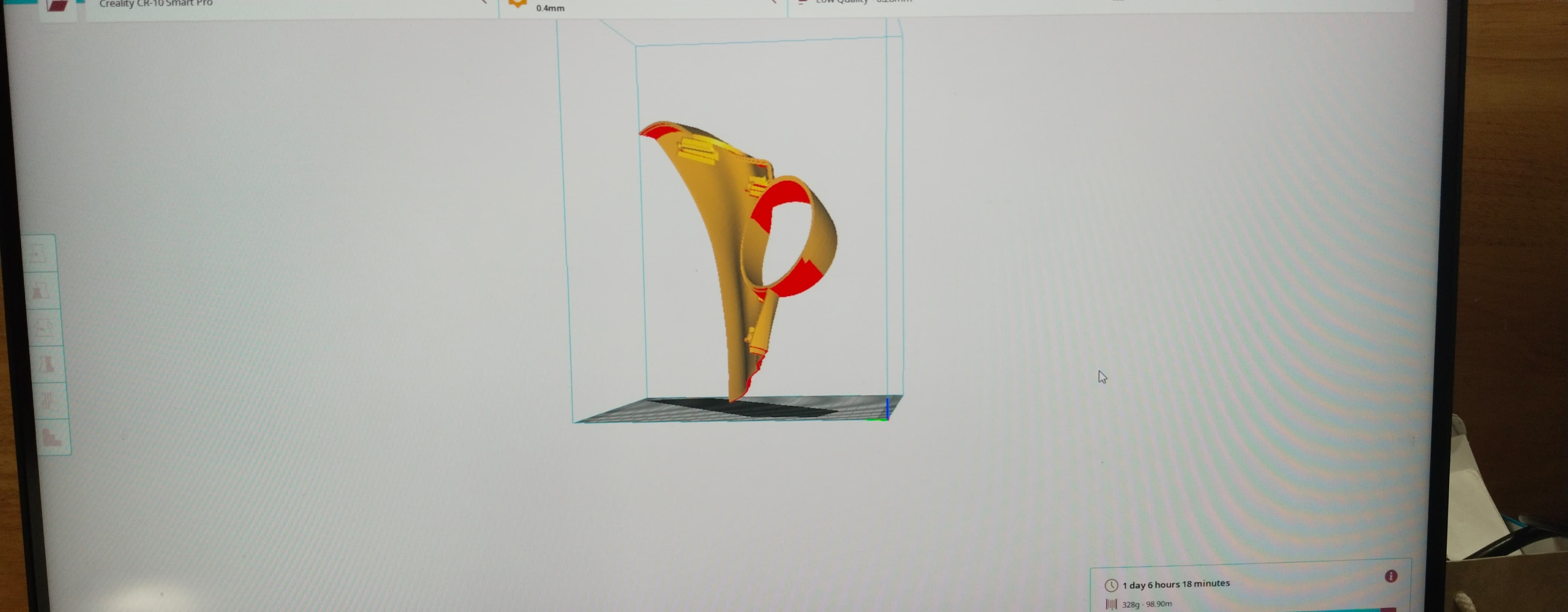
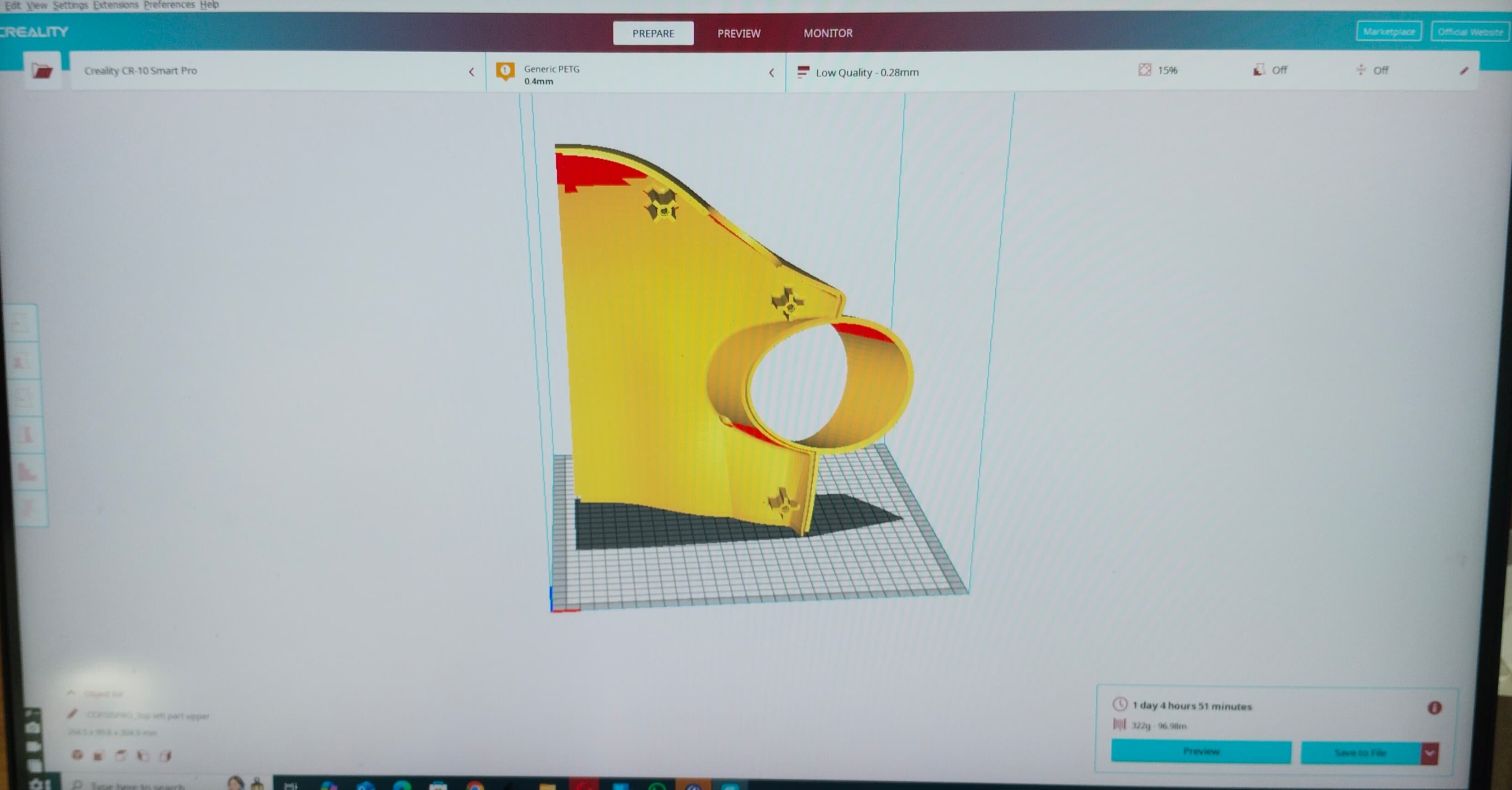
At first I divided my drone into 8 parts and to do the 3D printing, in sllicing part I used the creality software, after I loaded it that part didn’t set properly of its own creality is not supported that much to do the slicing
So I use the rotation options and make it proper orientation
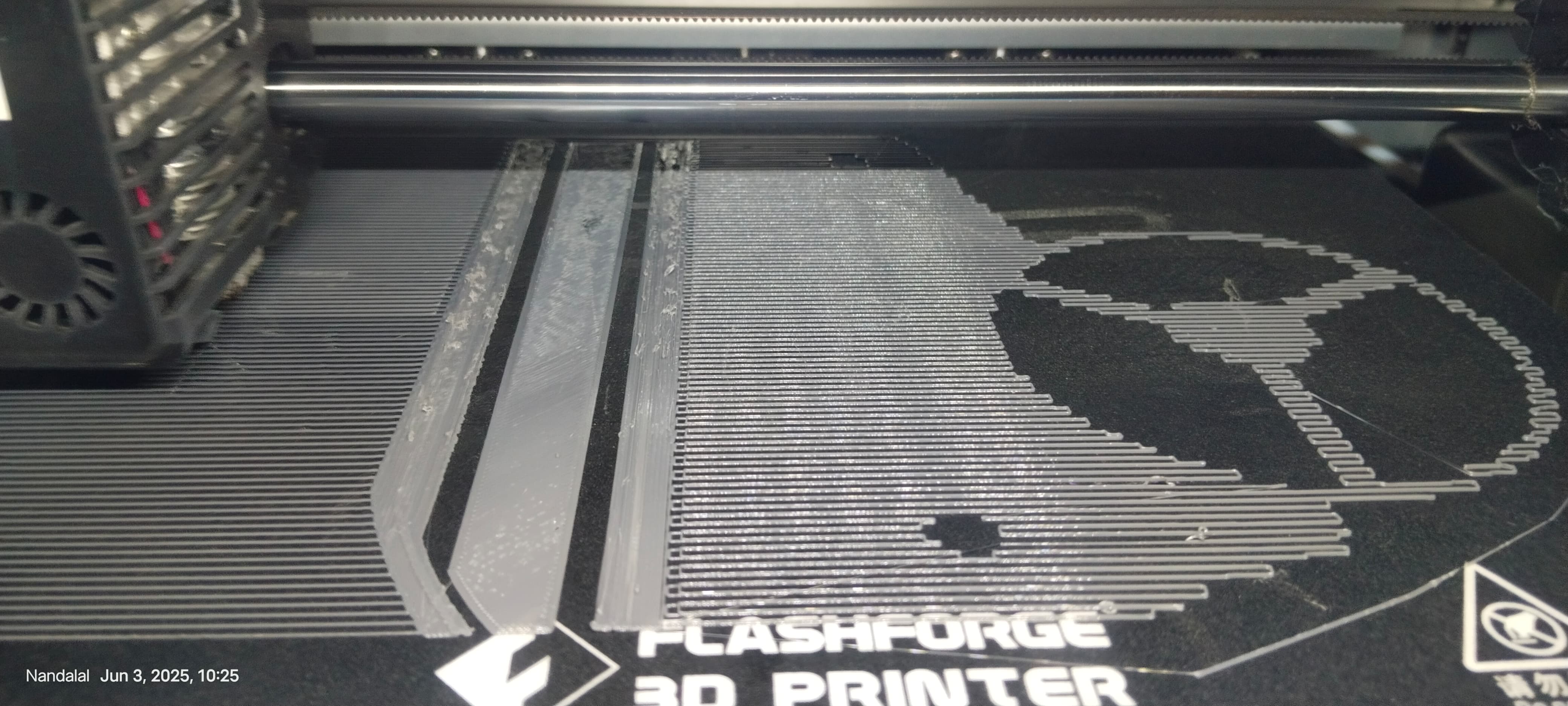
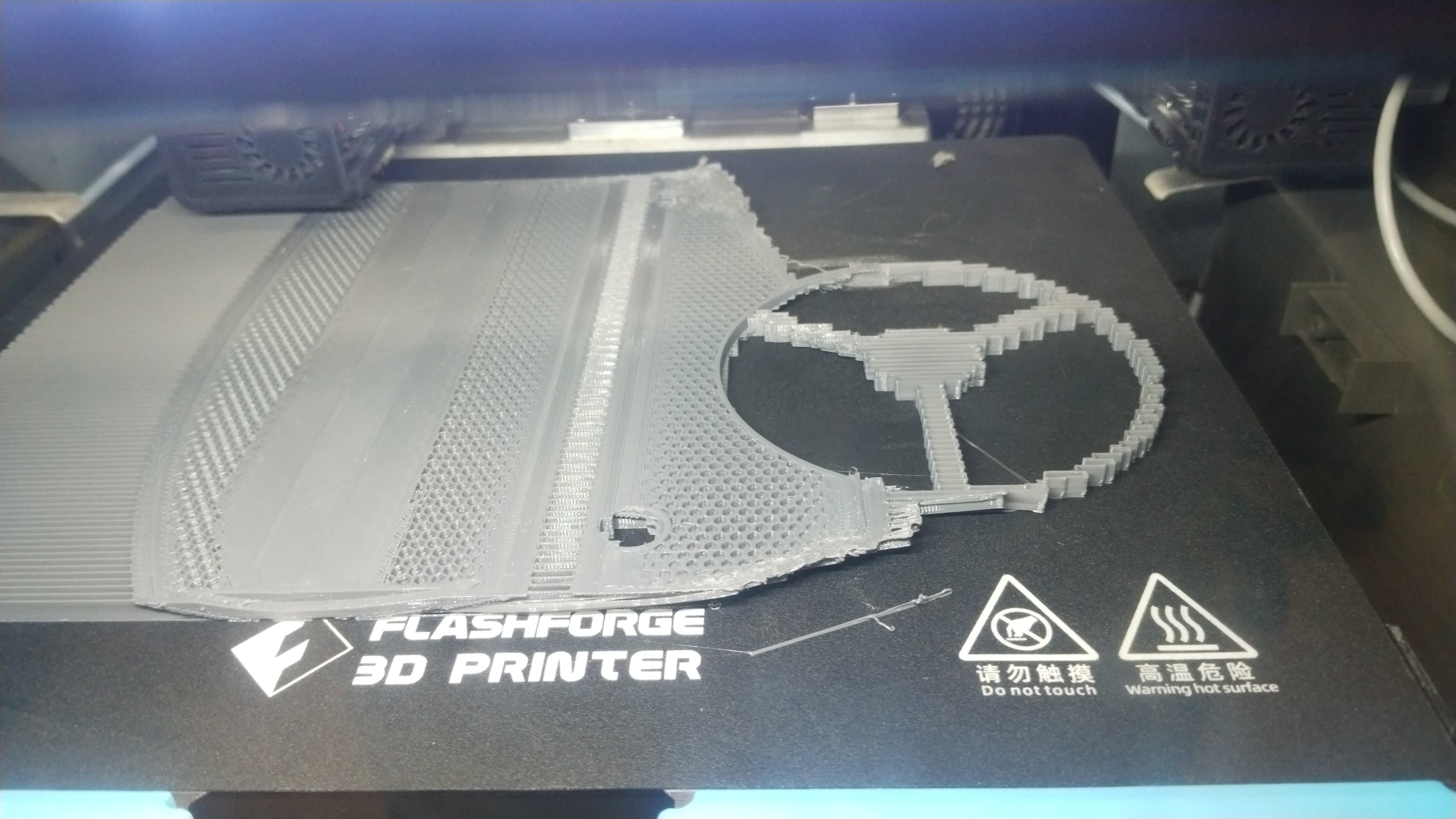
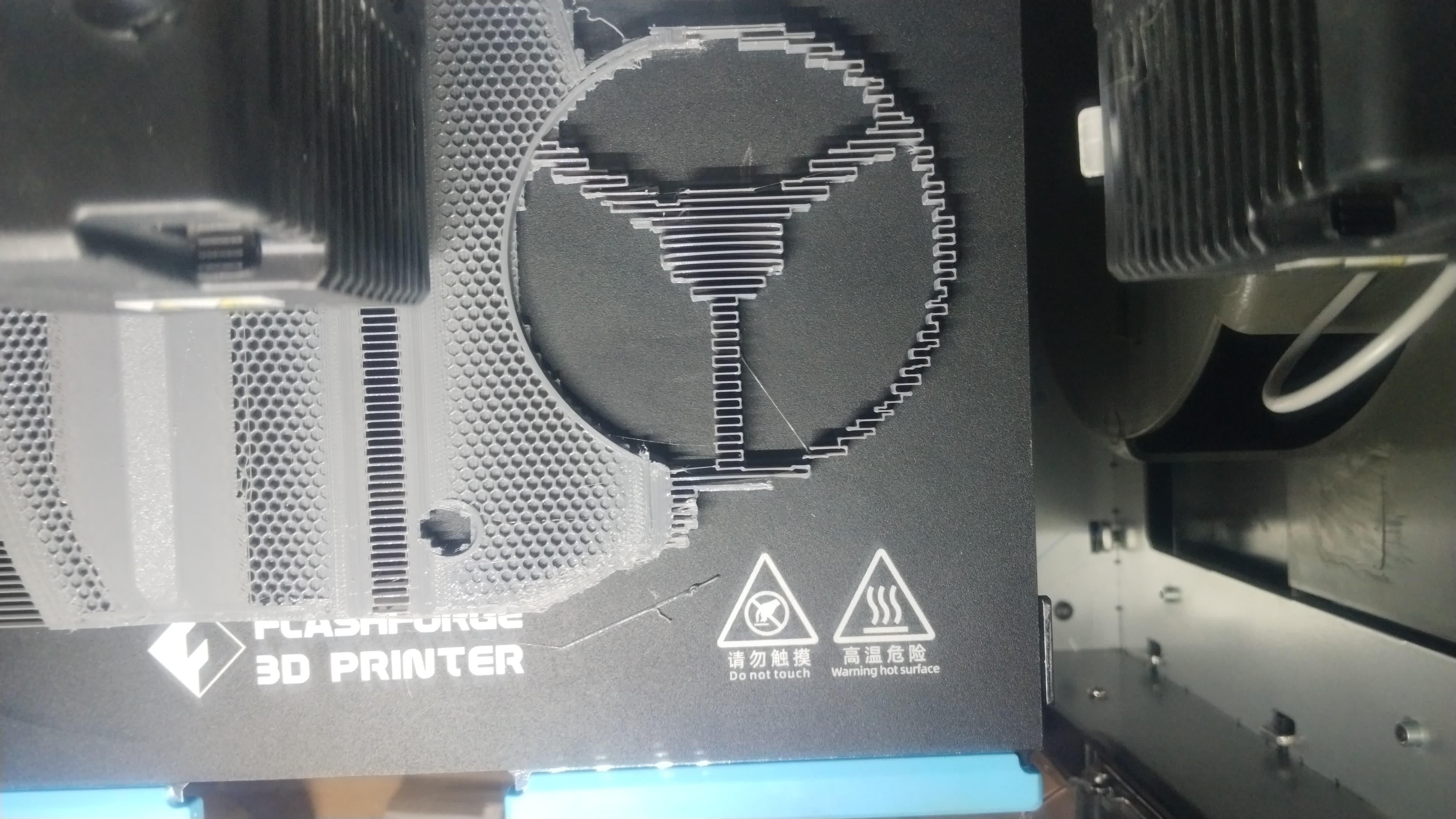
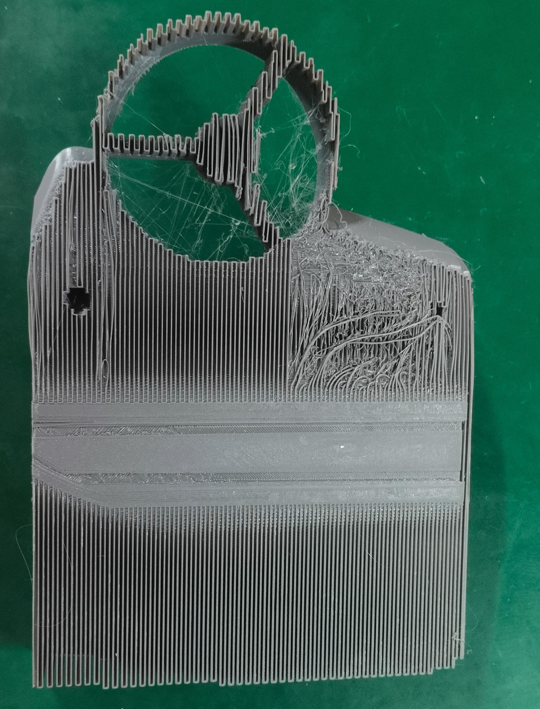
After the slicing I import the gcode into the machine and start printing. But I check the base its printing in outside of the base
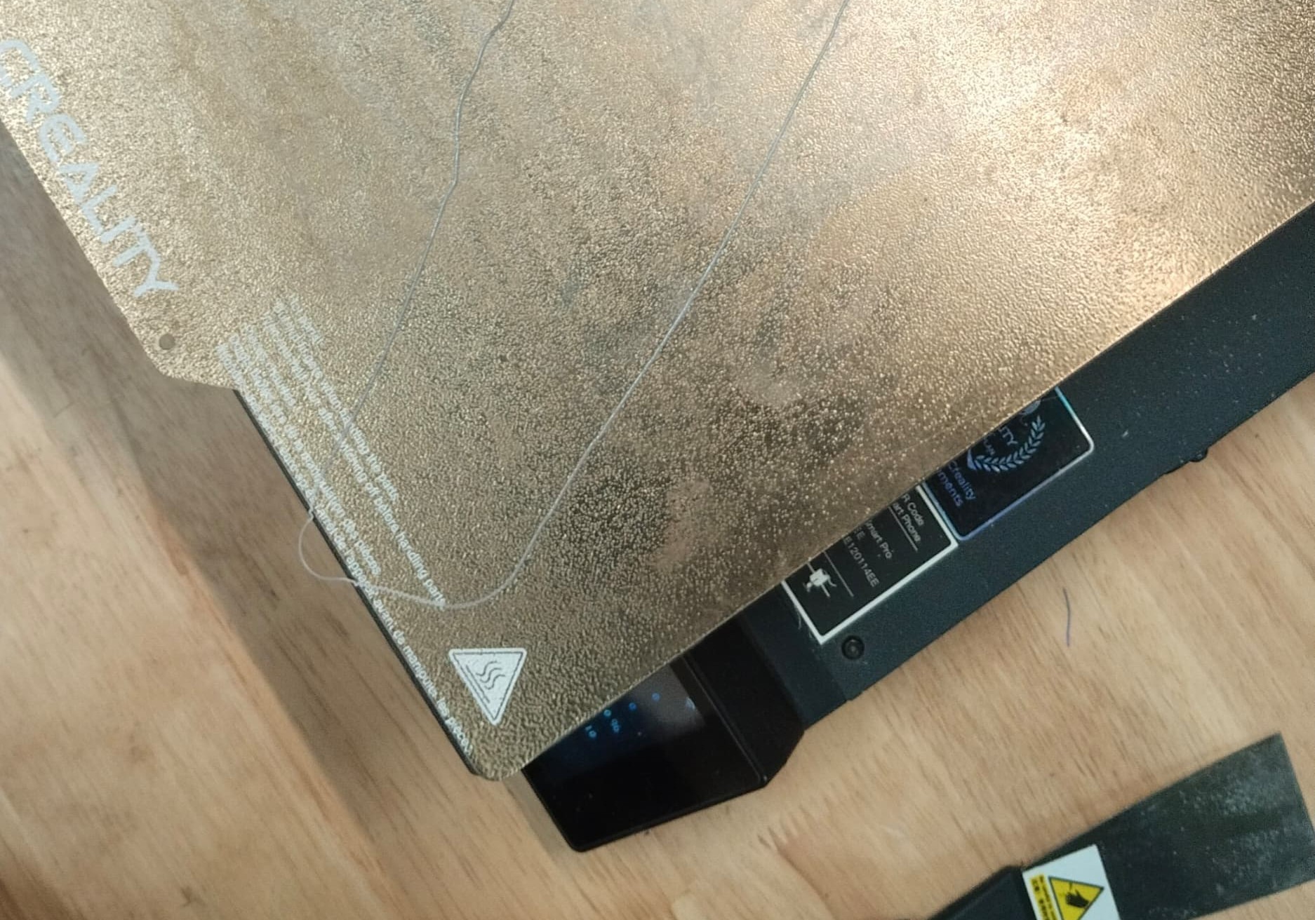
Even though I set it into the software right position its printing like this
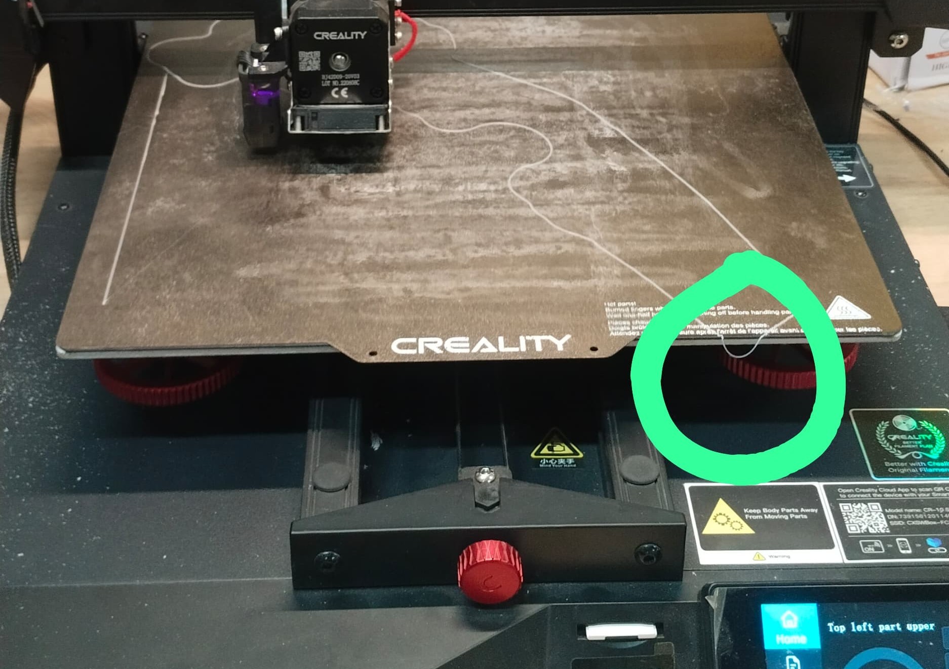
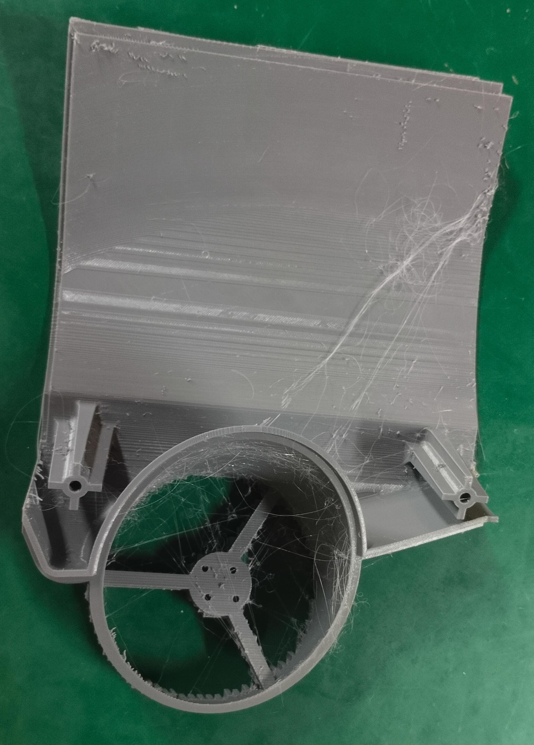
That is the raft part so I consider to minimize this error manually, so I moved the base plate little bit in front side so it can be printing properly, but I was wrong after seeing the result
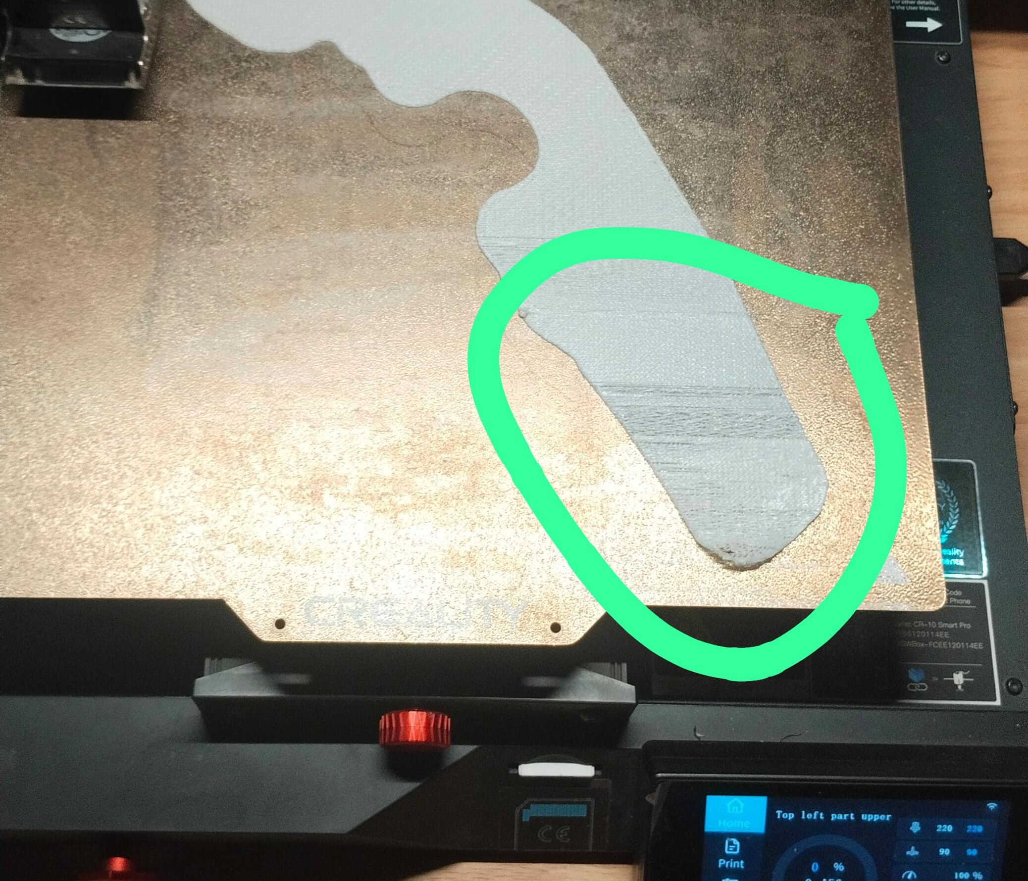
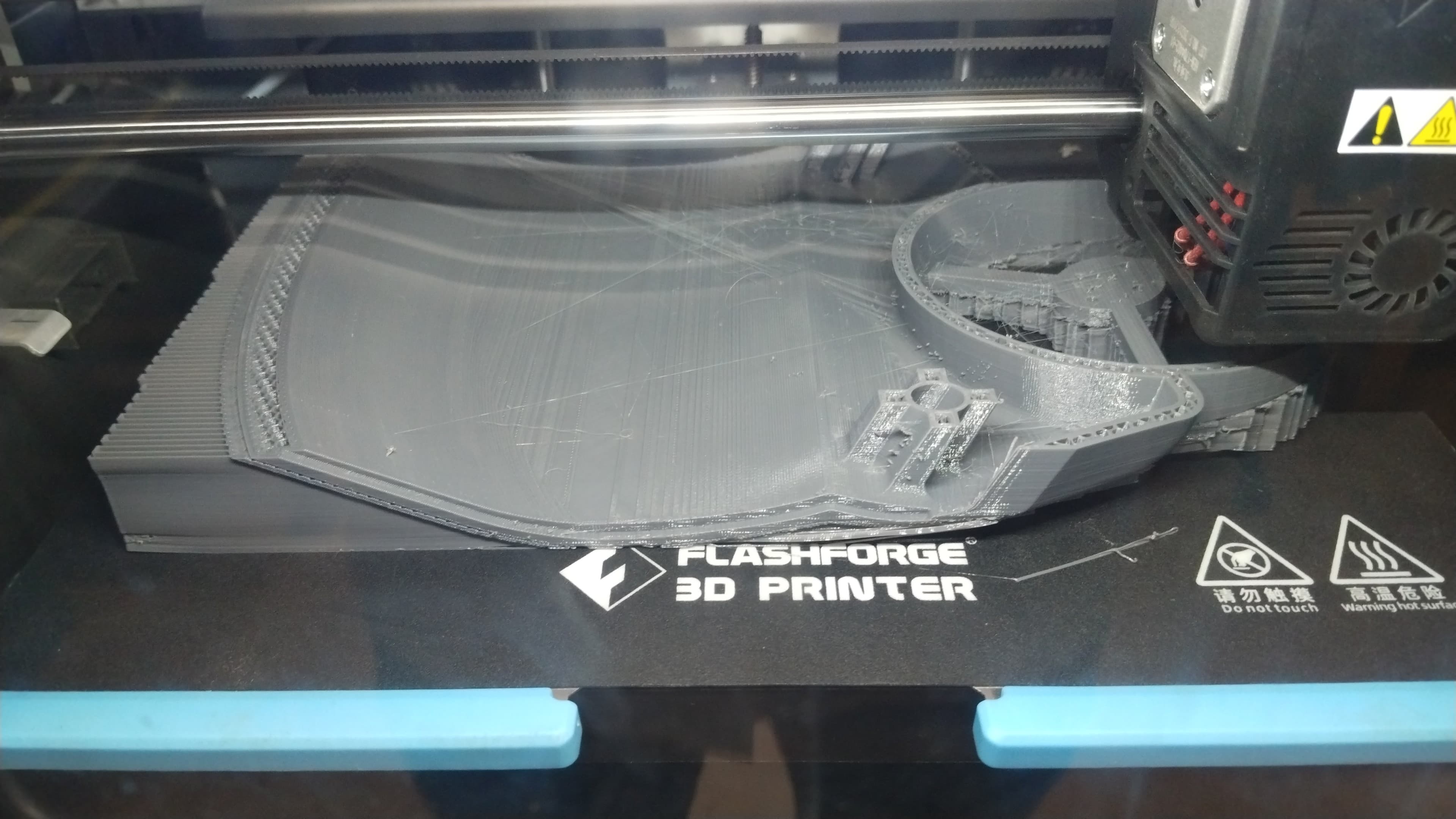
In the outside of the printing place there is not enough amount of heat is distribute so the printing parts of that place could not stick properly.
Still I can’t further do next step because the design is too large for this printer as well, so again I consider to divide it into total 14 parts and do the printing by Flash Forge Printer.
2026 FABLAB
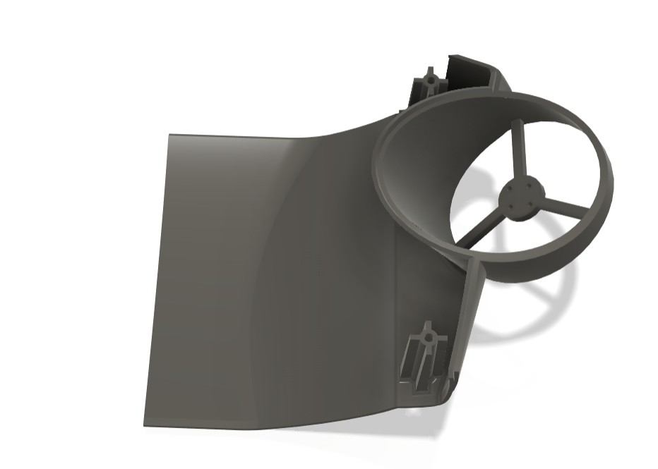
3D Printing of the reworked Underwater Drone Components
After completing the design modifications and exporting all components as individual STL files, I began the fabrication process using 3D printing. The components were printed one by one to ensure proper quality control and to monitor the printing parameters for each part.
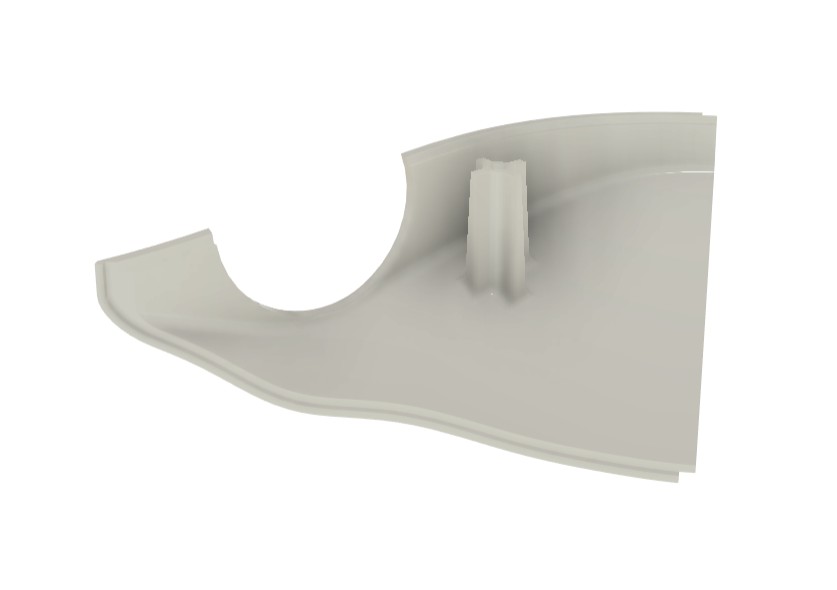
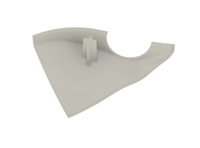
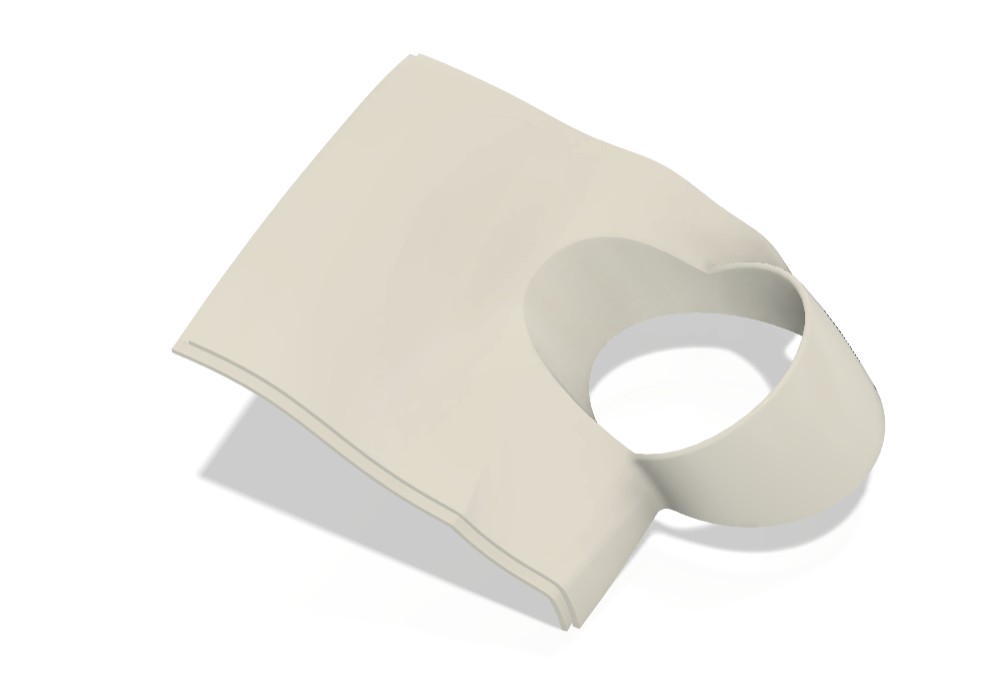
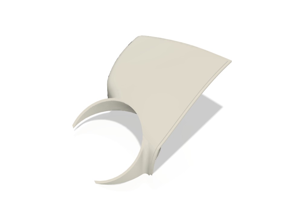
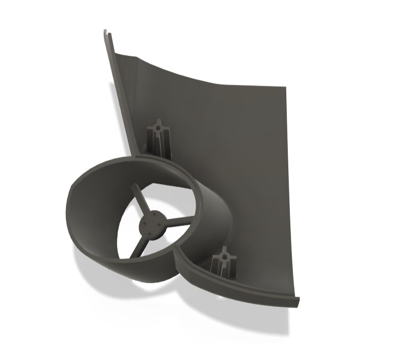
I started with the top section of the underwater drone. Before slicing the model, I evaluated different printing orientations to determine the most suitable position for minimizing support material while maintaining print quality and dimensional accuracy.
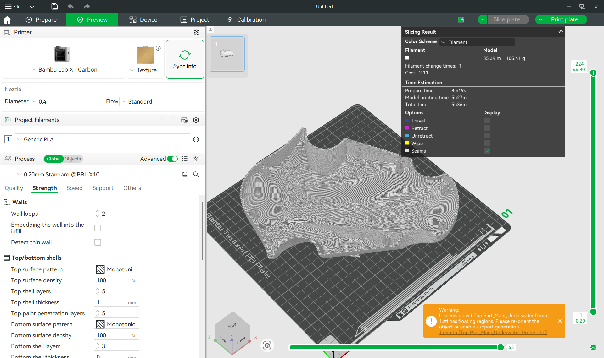
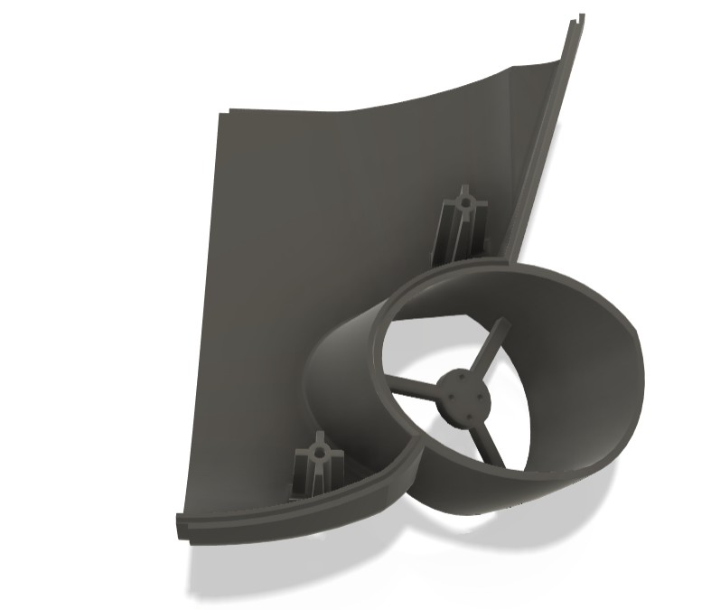
Once the optimal orientation was selected, I configured the required slicing parameters, including infill pattern, infill density, layer settings, support generation, and material selection. After completing the slicing process, the software estimated that the part would require approximately 175 grams of filament, including the support structures.
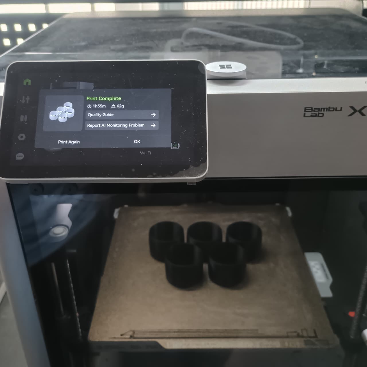
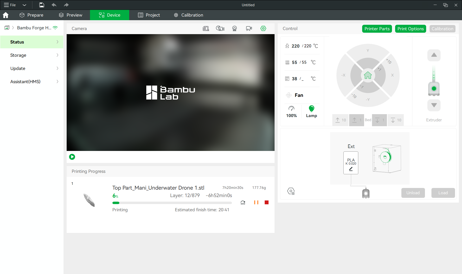
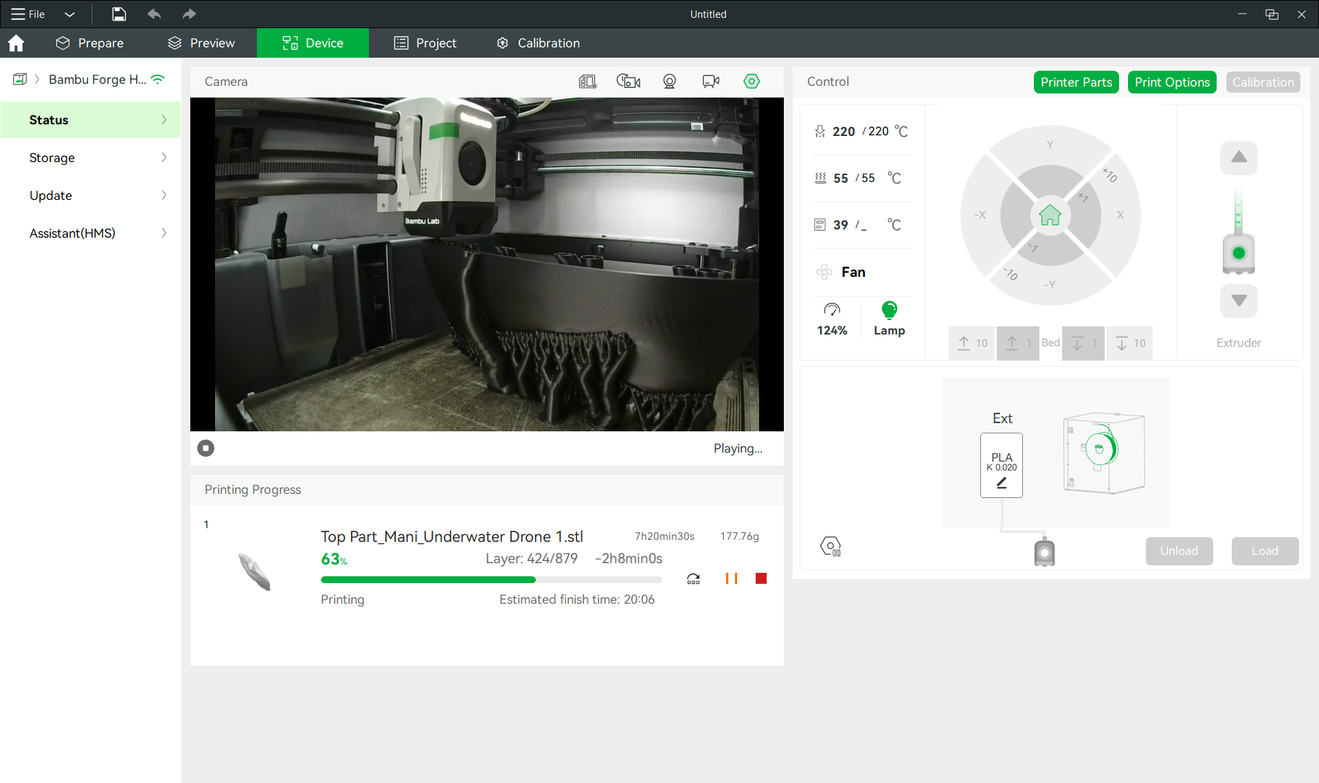
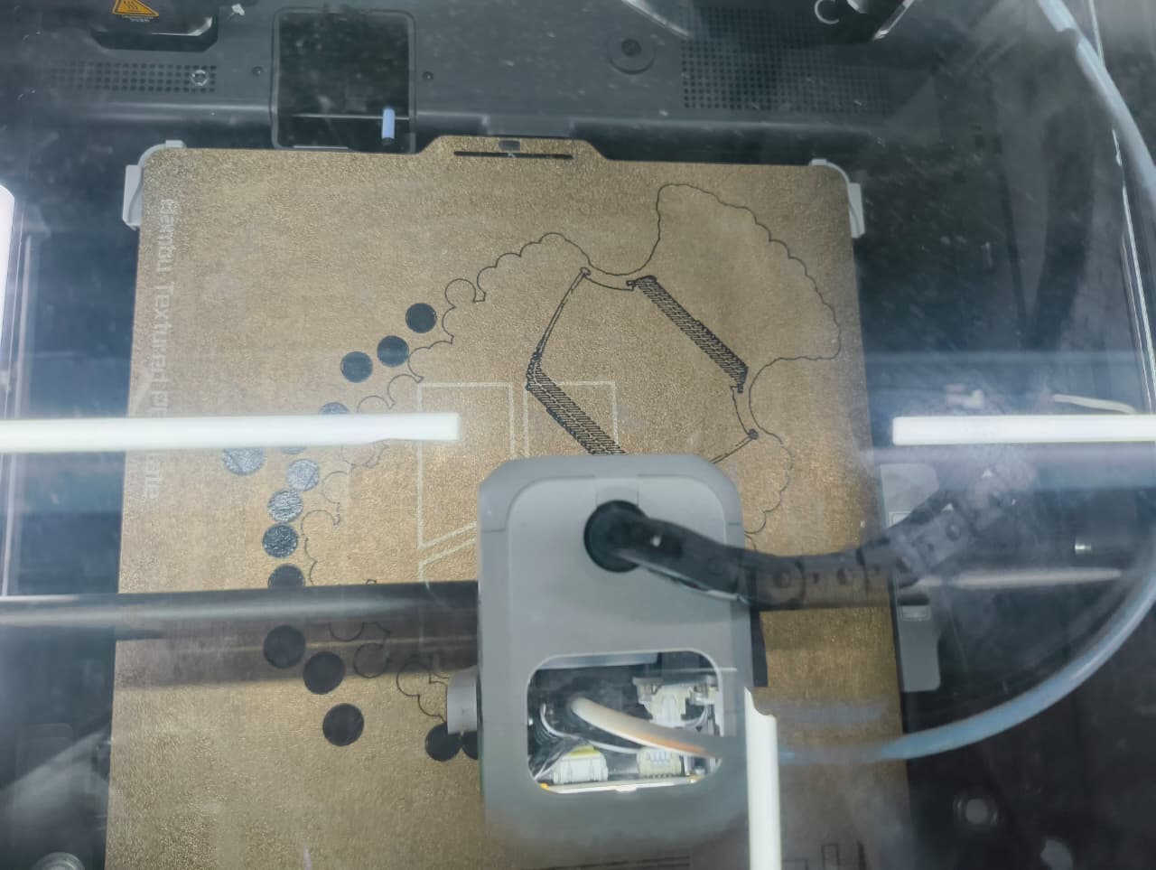
The generated G-code file was then transferred to the Bambu Lab 3D printer for fabrication. Before starting the print, the machine automatically performed bed leveling and system checks to ensure proper printing conditions. Once the calibration process was completed, the printer began manufacturing the component.
Bambu studio
Bambu Lab is a 3D printer manufacturer known for its high-speed CoreXY printers with advanced automation features. The X1 Carbon is one of its flagship models, offering AI-assisted printing, automatic calibration, and support for engineering-grade materials.
In our lab we have Bambu Lab X1 Carbon 3D Printerr
Specification
| Print Size (L x W x H) (mm) | 256 × 256 × 256 |
| Machine Size (mm) | 389 × 389 × 457 |
| Printing Speed (mm/s) | Up to 500 |
| Maximum Acceleration | 20,000 mm/s² |
| Printing Technology | FDM (CoreXY) |
| Nozzle Diameter (mm) | 0.4 mm (Optional: 0.2/0.6/0.8 mm) |
| Screen Type | 5-inch Color Touchscreen |
| Nozzle Temperature (°C) | Up to 300 |
| Heatbed Temperature (°C) | Up to 120 |
| Filament Compatibility | PLA, PETG, TPU, ABS, ASA, PA, PC, Carbon Fiber Reinforced Materials |
| Data Transmission Method | Wi-Fi, LAN, MicroSD Card |
| Camera | Built-in AI Monitoring Camera |
| Auto Calibration | Yes |
| Approximate Price | ₹1.2 – ₹1.5 Lakhs |
Material Selection
For this iteration of the underwater drone prototype, I selected PLA+ filament for printing all structural components. Compared to standard PLA, PLA+ offers improved mechanical strength, better durability, and enhanced impact resistance, making it more suitable for functional prototype applications.
In addition, PLA+ provided a cost-effective alternative to PETG while still delivering sufficient rigidity and dimensional stability for the proof-of-concept model. Since the primary objective of this prototype was to demonstrate the design concept and mechanical integration, PLA+ was considered the most appropriate material choice.
After loading and configuring the PLA+ filament in the printer, the printing process was initiated and the fabrication of the first drone component began.
Printing and Validation of the Drone Components
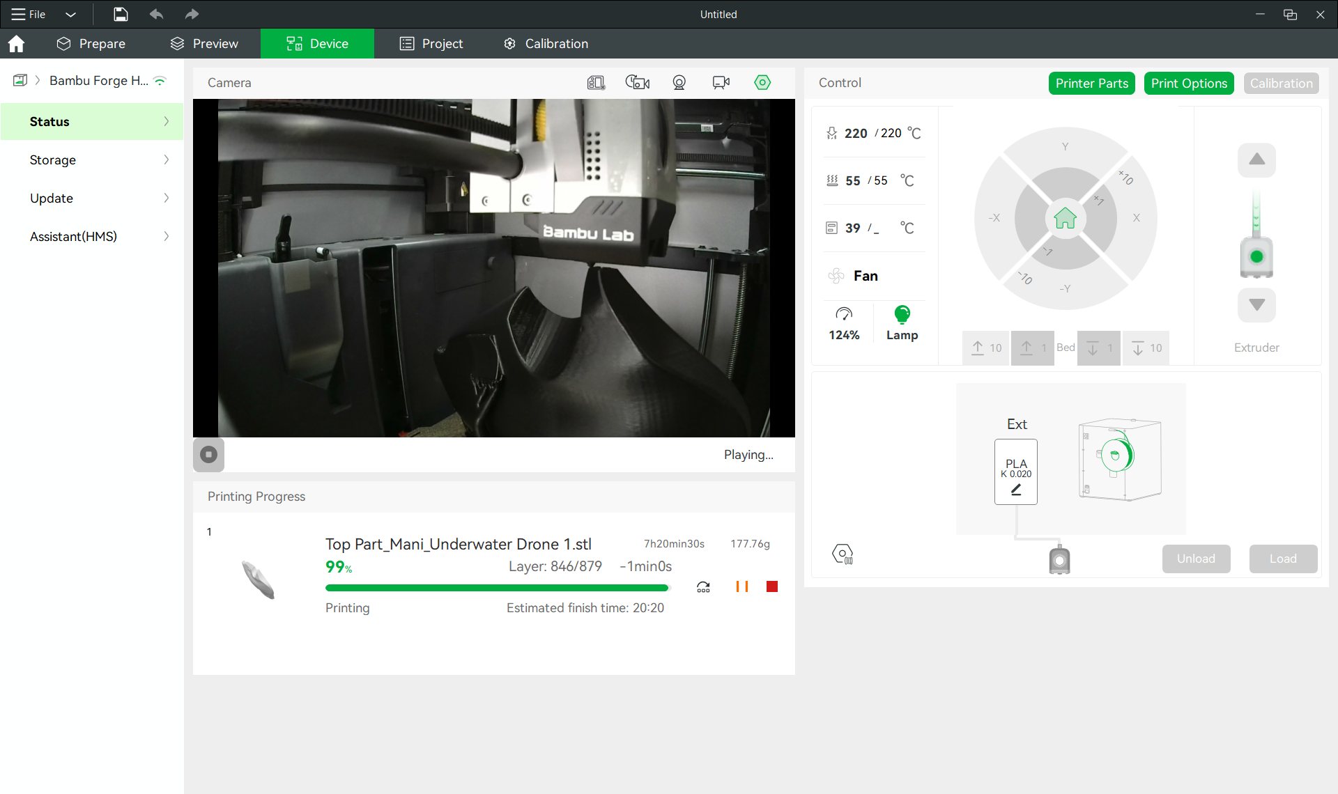
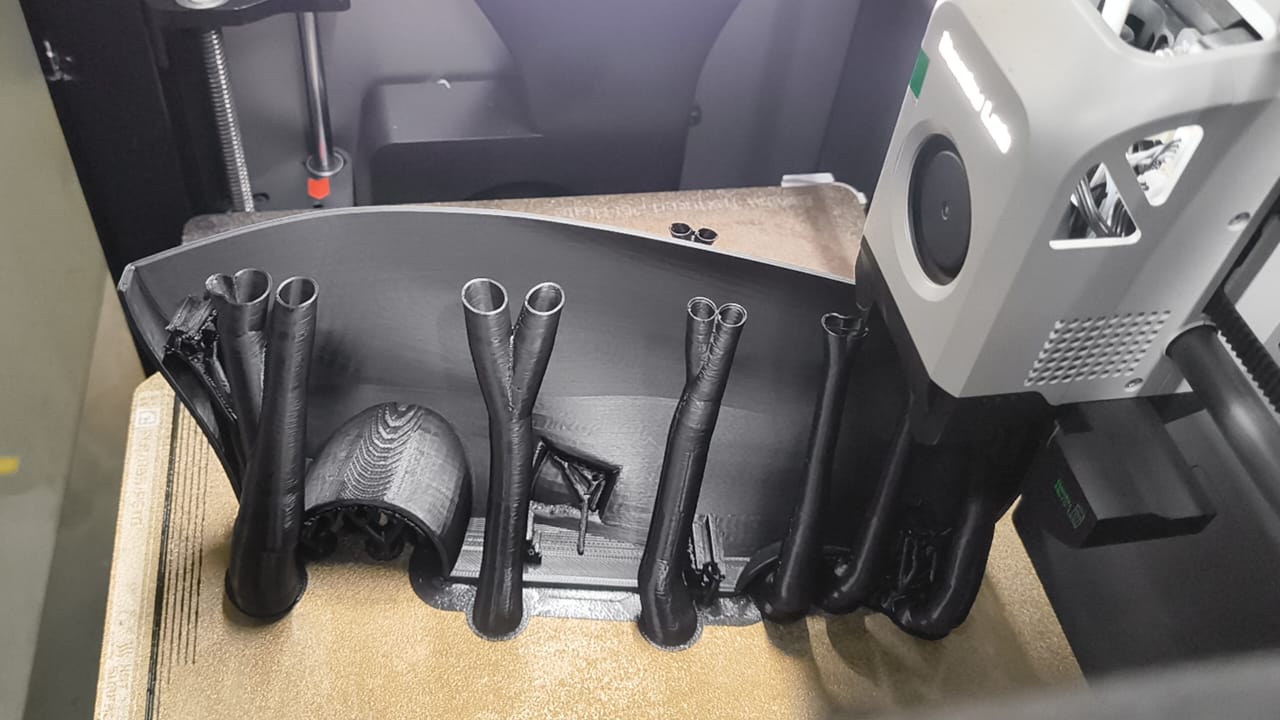
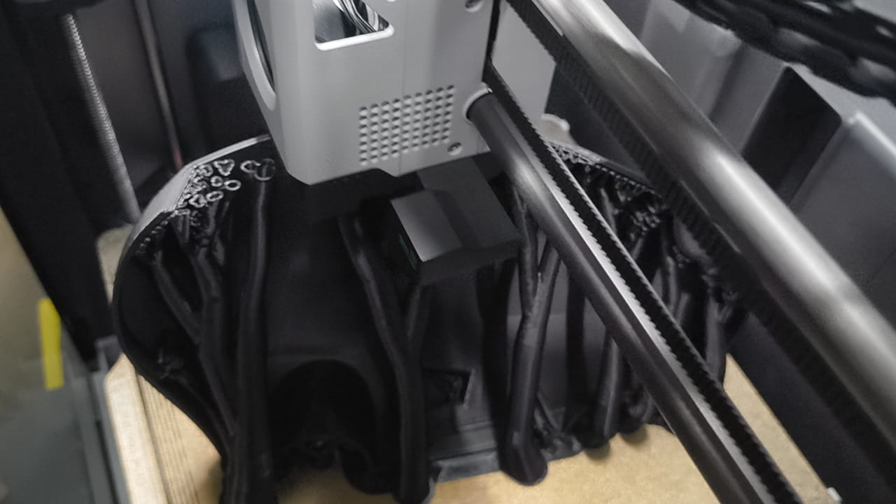
After approximately seven hours of printing, the top section of the underwater drone was successfully completed.
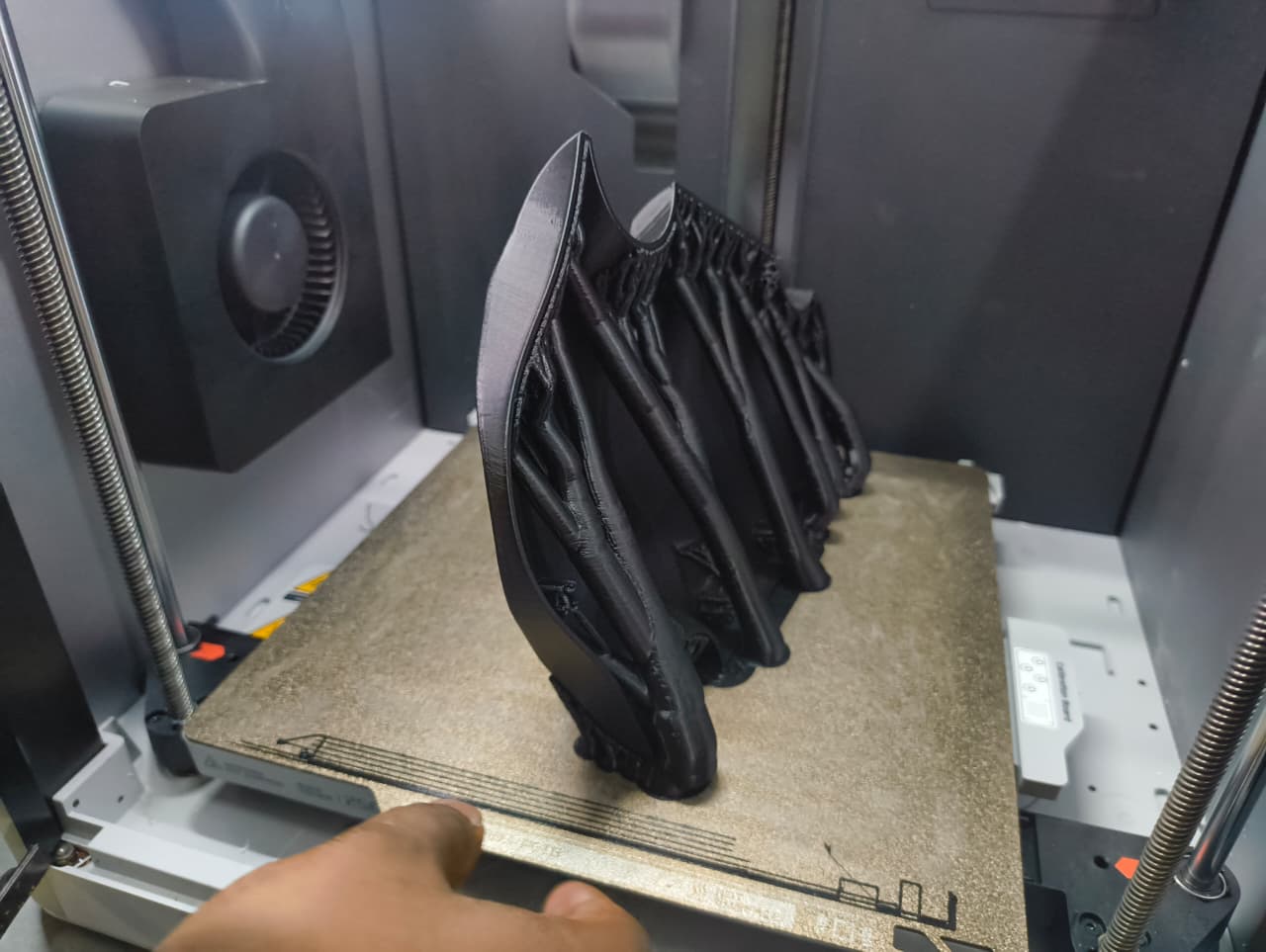
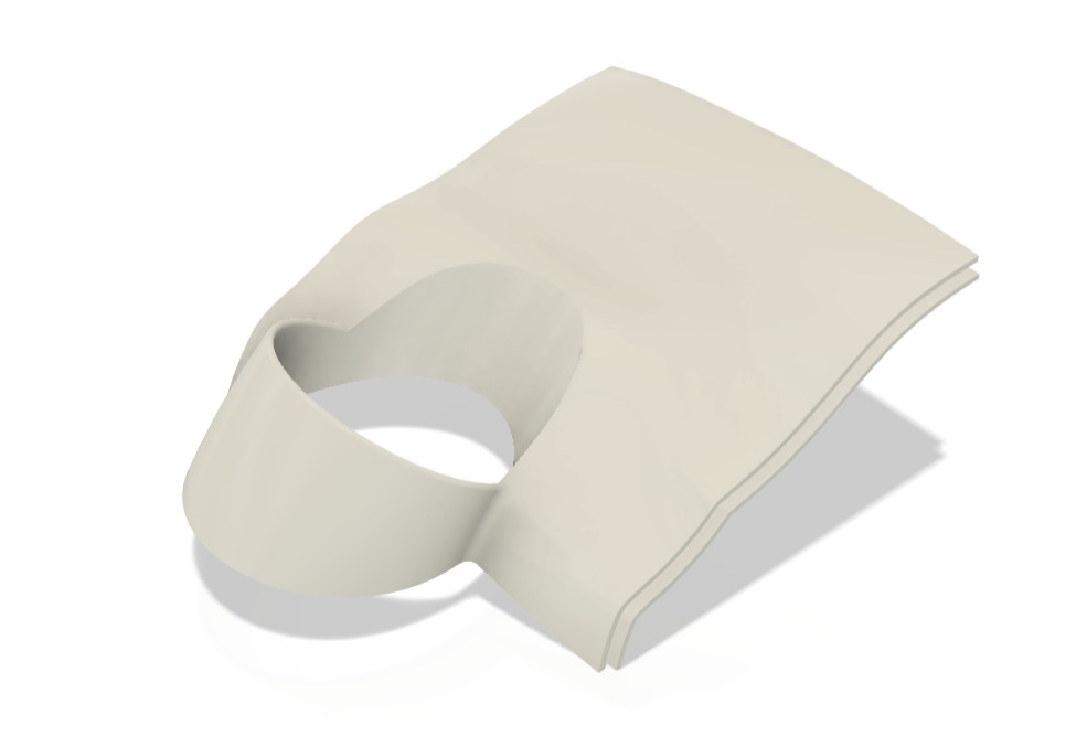
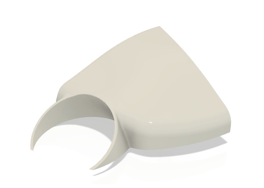
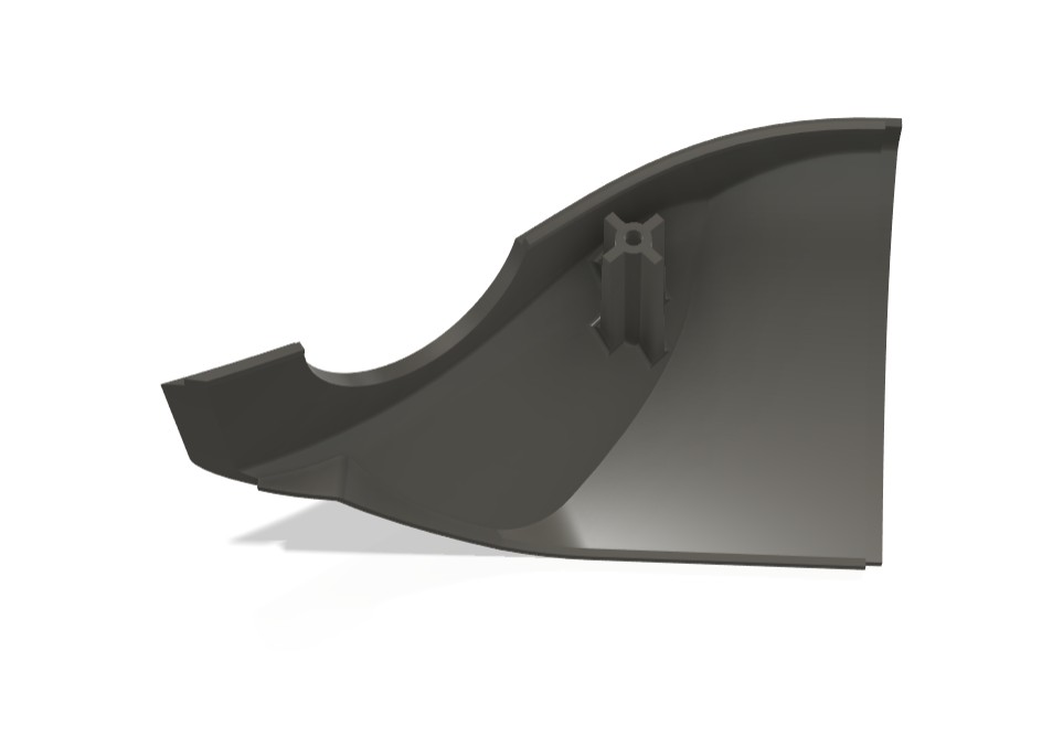
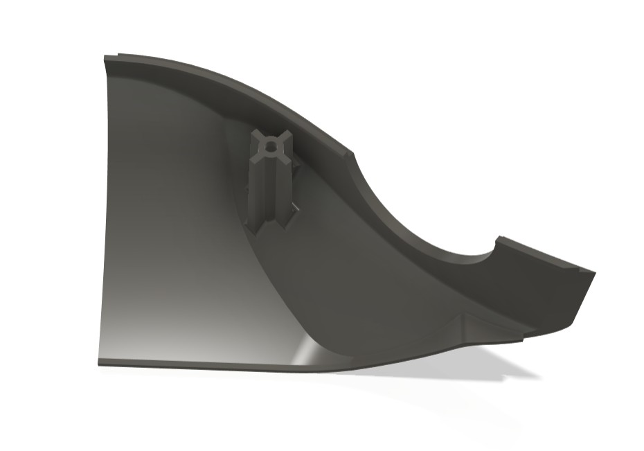
Following the successful fabrication of the top section, I proceeded with the bottom section of the drone. Similar to the previous component, I optimized the print orientation and configured the necessary slicing parameters before generating the G-code. The file was then sent to the 3D printer for fabrication.
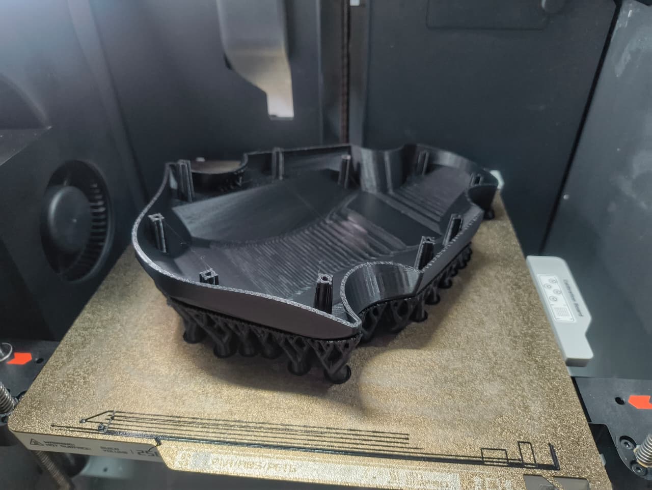
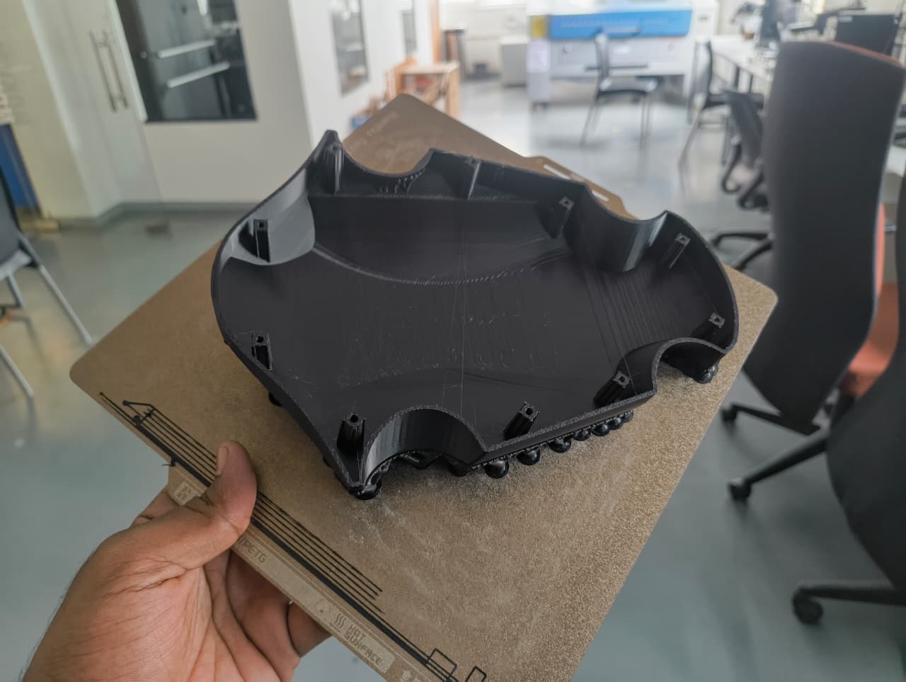
After the printing process was completed, the bottom section was removed from the printer and all support materials were carefully cleaned from the part. Additional post-processing was performed to remove any remaining support residues and improve the overall surface finish.
Component Inspection and Fit Verification
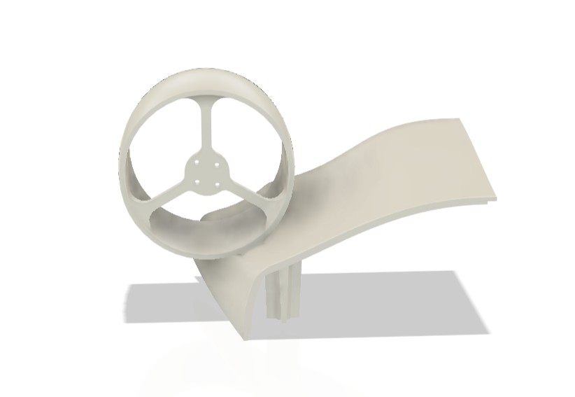
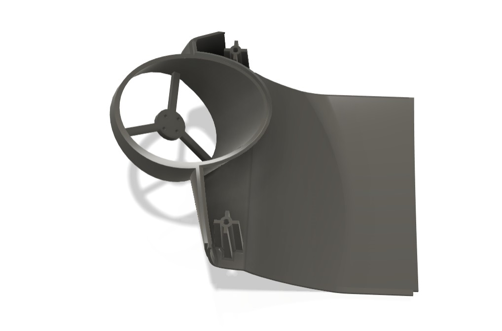
Once both major structural components were cleaned, I performed a detailed inspection of the printed parts. The alignment between the top and bottom sections was checked to verify dimensional accuracy and overall assembly compatibility.
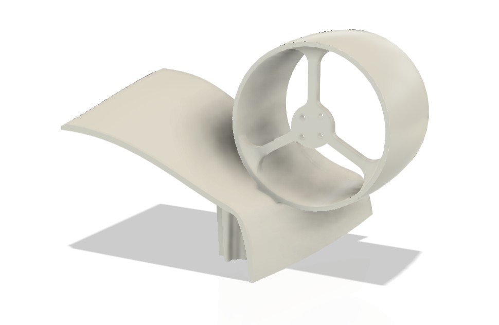
After validating the main body components, I proceeded with the fabrication of the motor hub assembly. The first motor hub was printed and used as a test component to verify the mounting arrangement and dimensional accuracy of the redesigned motor interface.

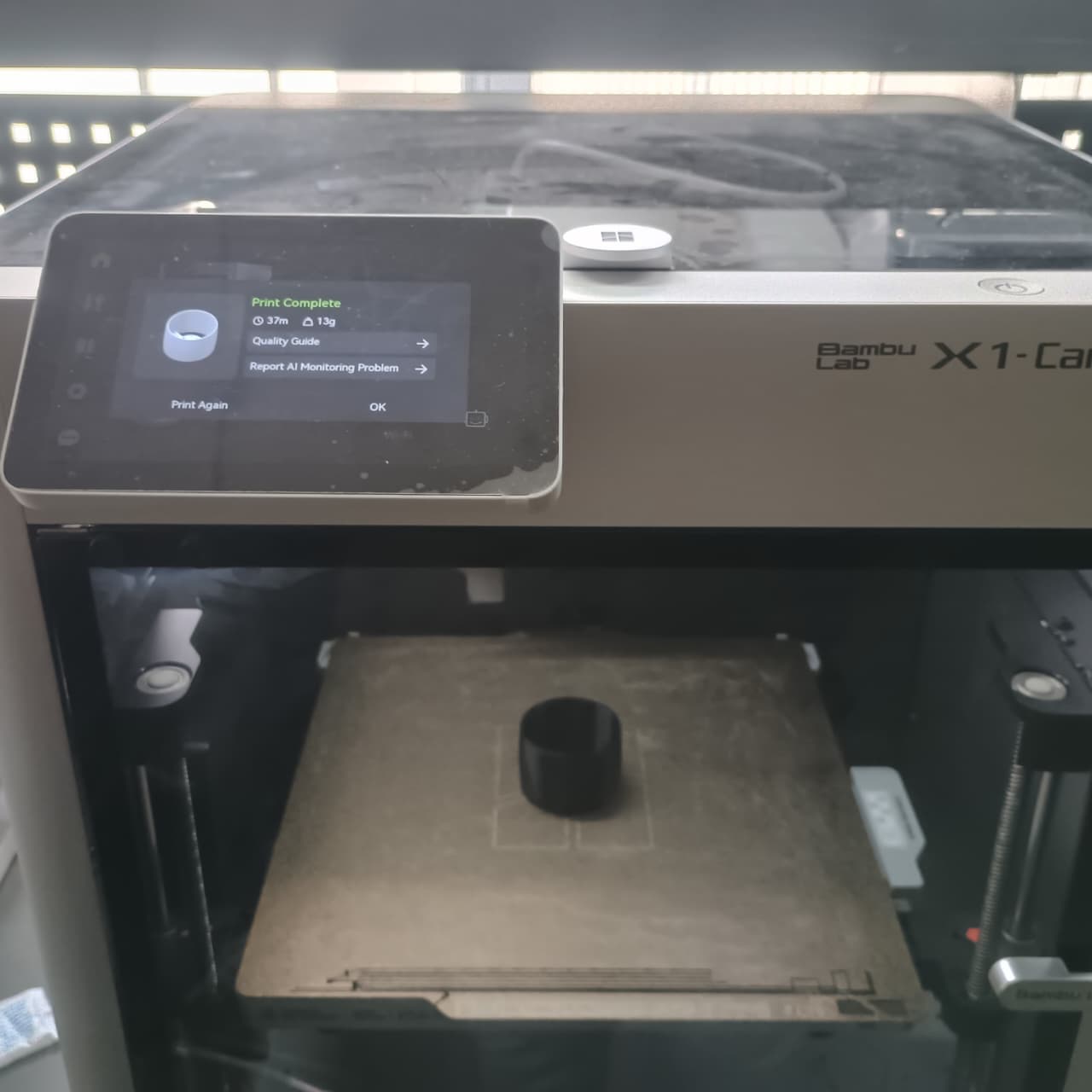
Once the print was completed, I assembled the motor hub with the selected motor and checked the alignment of the mounting holes. Bolts were inserted and tightened to confirm that the hole pattern matched the motor specifications and that the assembly could be securely fastened.
The test assembly demonstrated a precise fit, confirming that the redesign was successful. Based on this validation, I proceeded to print the remaining five motor hubs required for the drone. All printed motor hubs maintained the same dimensional accuracy and fit correctly with the motor mounting hardware.