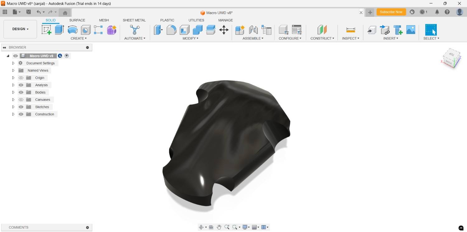
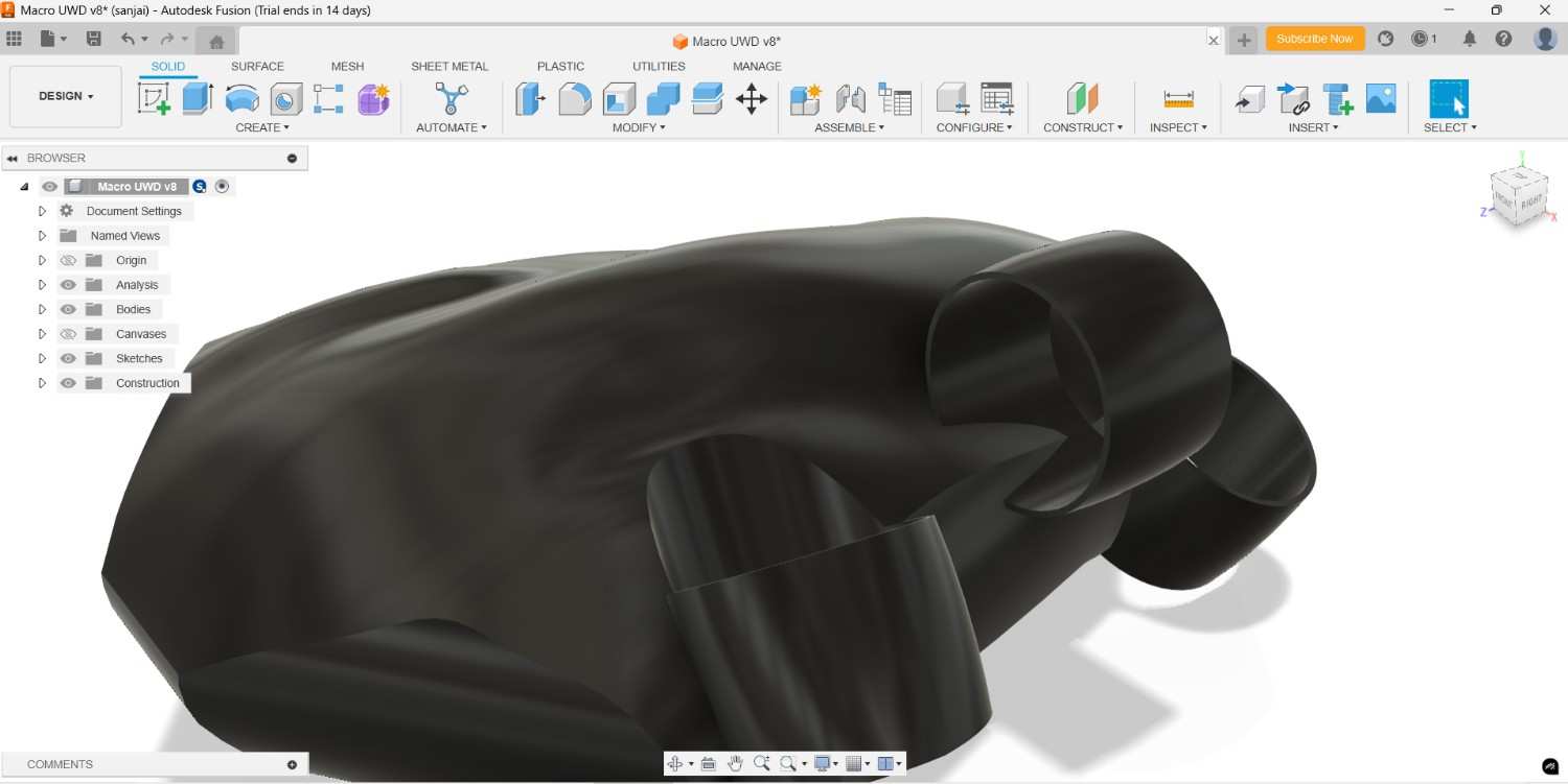
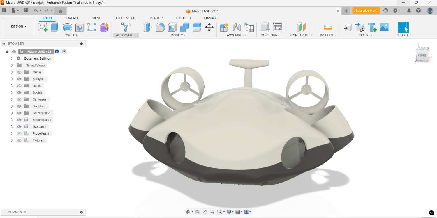
Final 3D Design
Back
2025 FABLAB
First I start with the 3D modeling, I selected the Fusion 360 software to design it completely
Fusion 360
Fusion 360 is a cloud-based 3D CAD, CAM, and CAE software by Autodesk. It integrates design, simulation, electronics, and manufacturing tools into a single platform. Users can create solid models, assemblies, and detailed drawings with parametric and freeform modeling. It supports FEA and CFD simulations for mechanical validation. Fusion 360 enables CNC machining, 3D printing, and generative design. Its collaboration features allow real-time teamwork and version control.
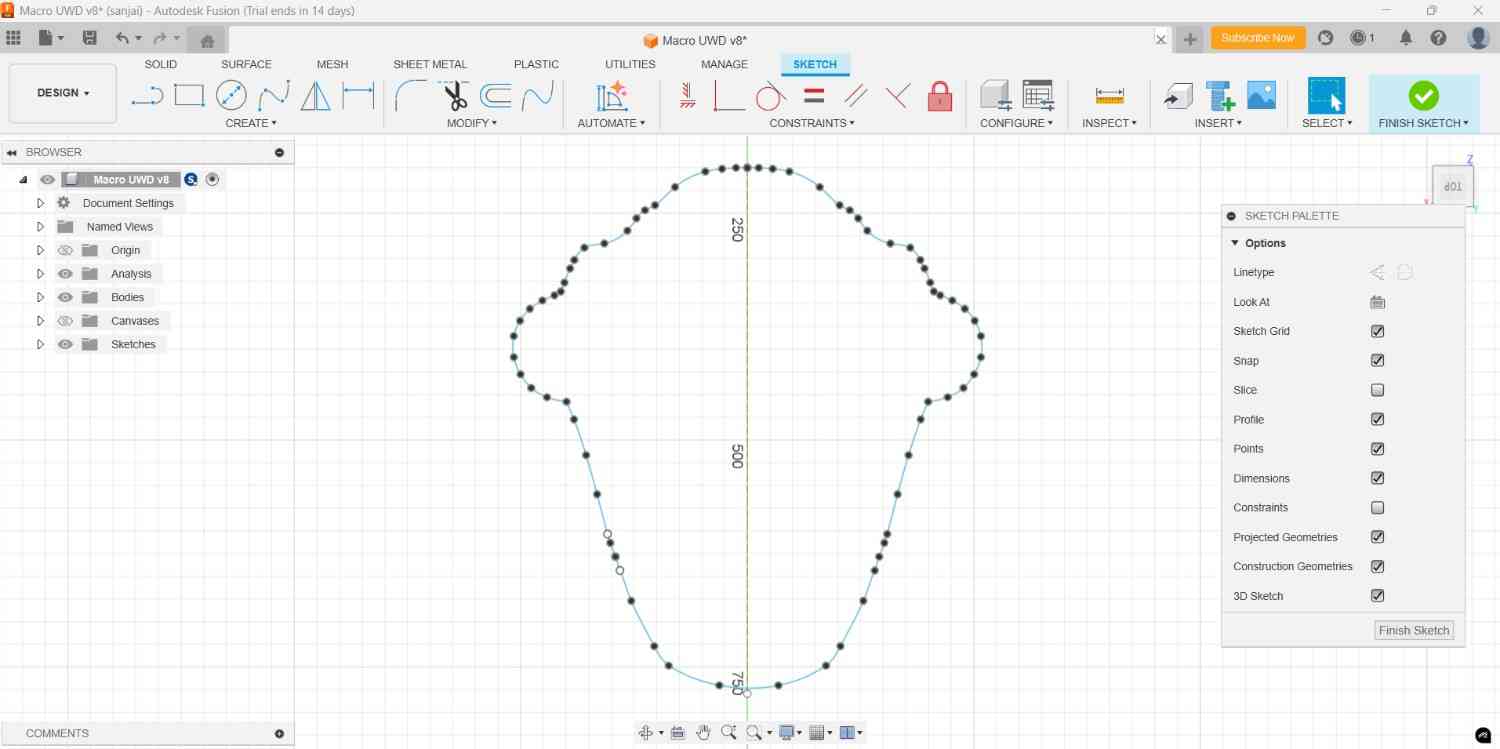
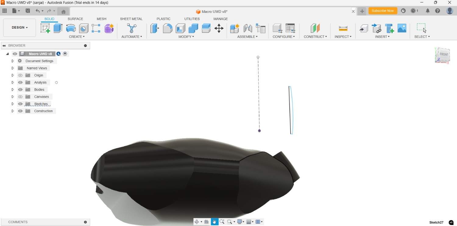
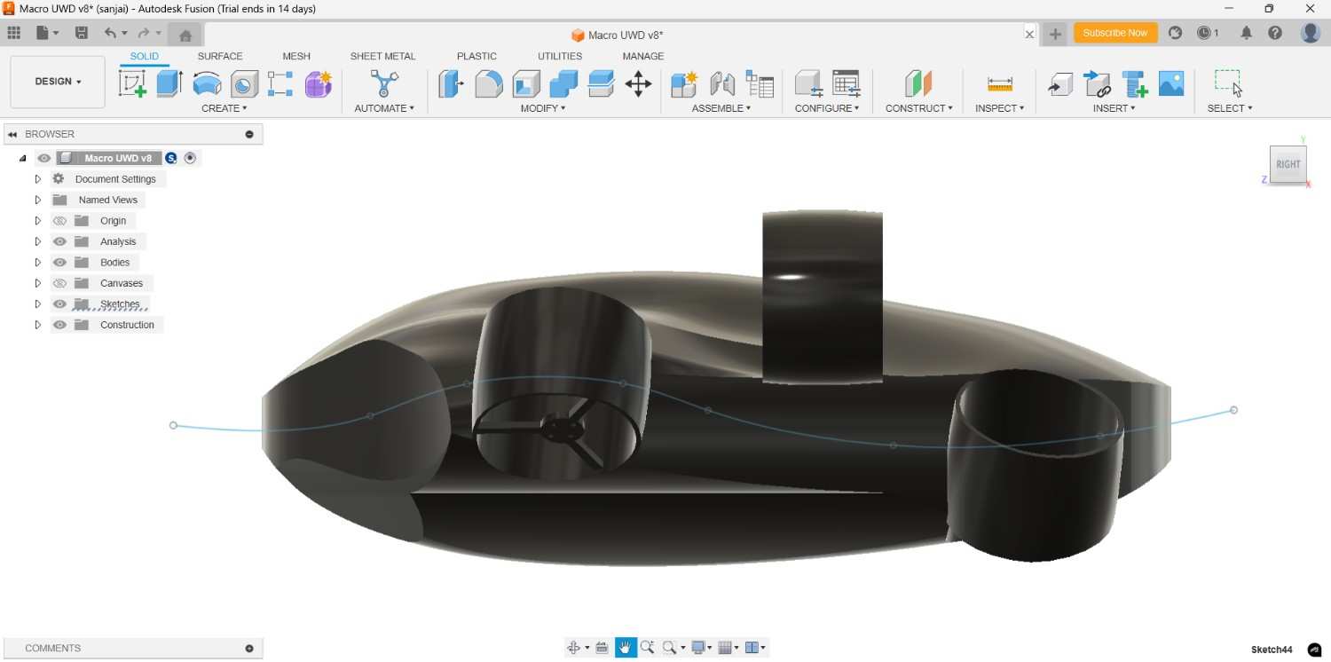
I planned my drone dimension approximately at first, then I start the rough sketch by using the spline obtion in Fusion sketch. I also took the one reference image from online to draw this.
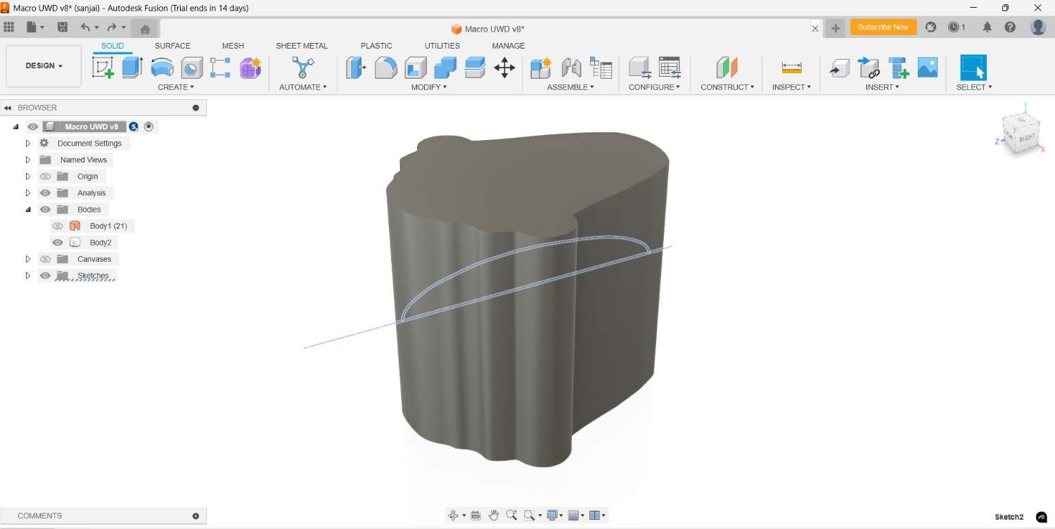
After I extrude it upto my required height with the help of Extruder command. Then i start the surface modeling method, I draw the spline and adjusting it with its lines
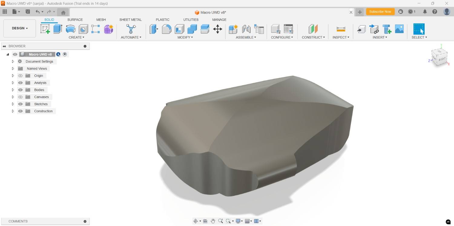
I cut the extra regions in the extruder part according to my perspective by using the split body command in side and front view
For the base design I did it properly, now I work on more with the detailed design. I create the one pillar respective to the drone drifting degree, then I place it into the determined position for the perfect orientation.

Then cut the body by using that angular body by using the combine tool, I select the main body as target body and the angular pillar as tool body and make the cut operation.
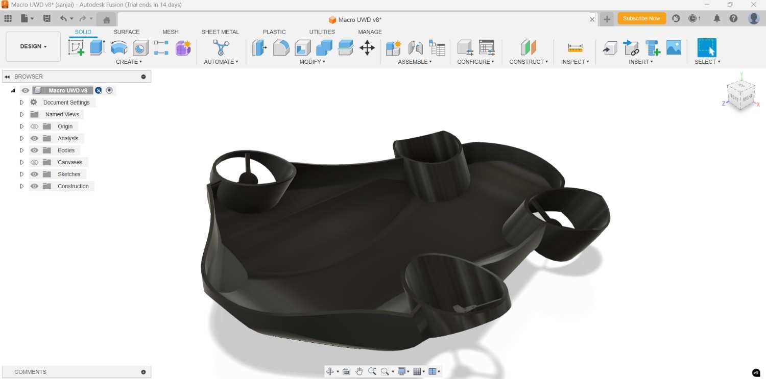
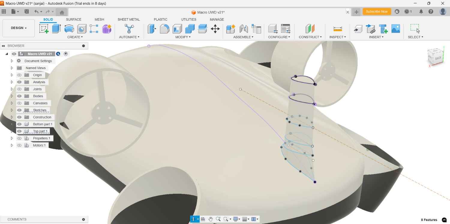
Then I go deep into the surface modeling, I create the offset plane with respective to my surface enhancement, draw the sketch by using the spline command.

After done the spline curved adjustment I did the cutting operation by took the spline as reference,
then cut the body in center by two, then recreate the body by using the mirror tool without changing the symmetry of either side.
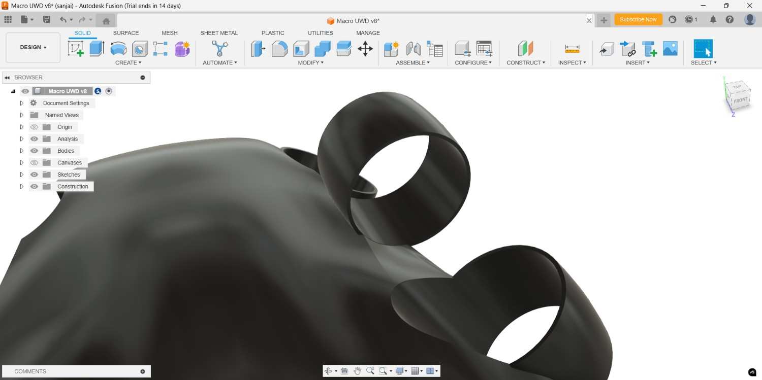
For the Motor and Propeller I draw the motor casing, I draw the line and use the arc command to close that, then adjust the position by dimension and revolve it by take one line as center.
At first I placed it the required position, but the it seems like some modification is needed to take the best output
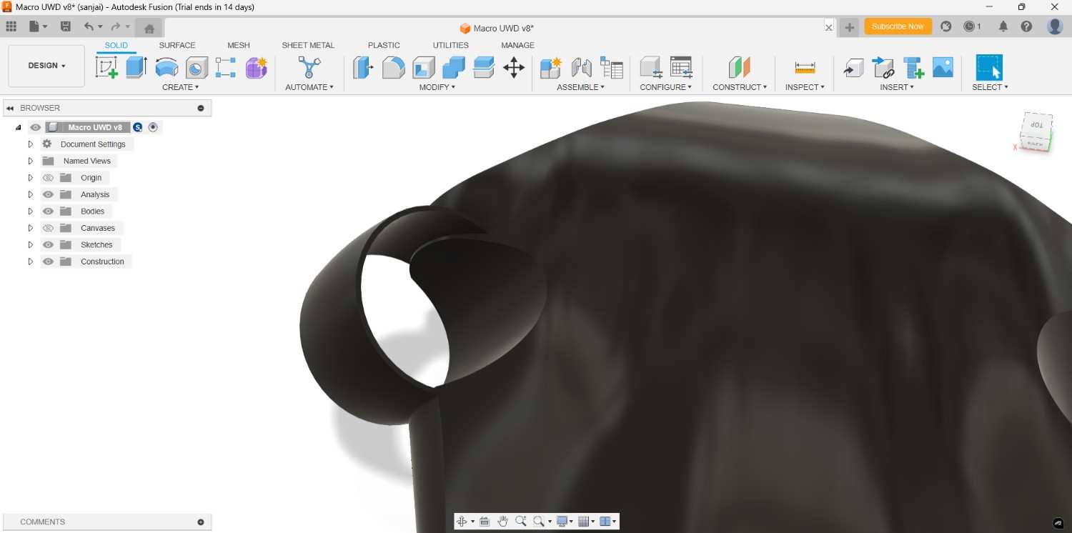
Inner side of the casing the body came little bit so I use the split body command to rectify that.

Like that I am also do the same thing in back side and middle of the drone too
Then again I made some modifiaction for the proper design, then only it could be more dynamically function.
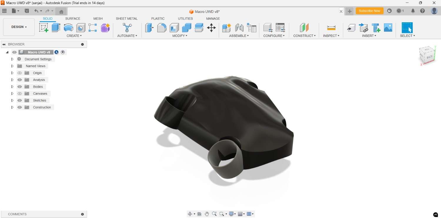
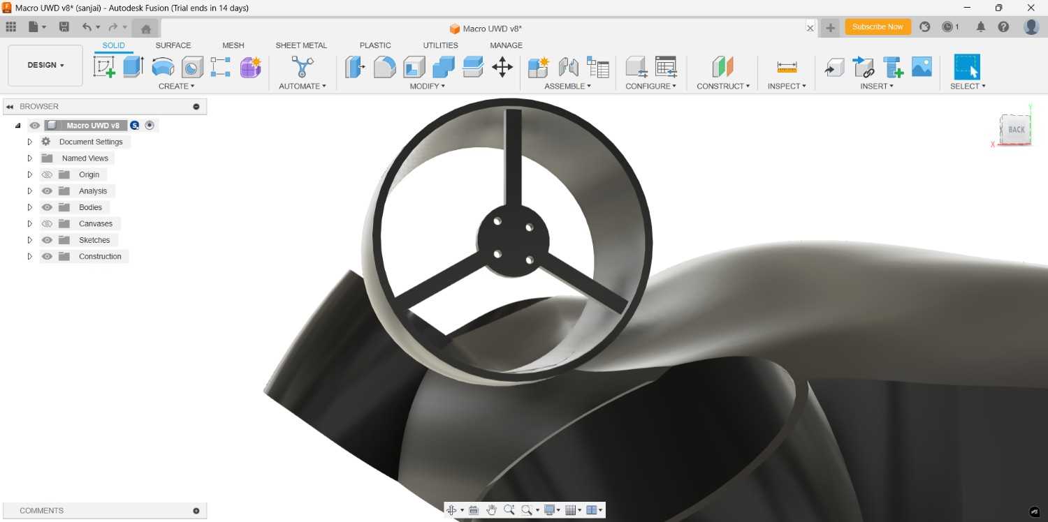
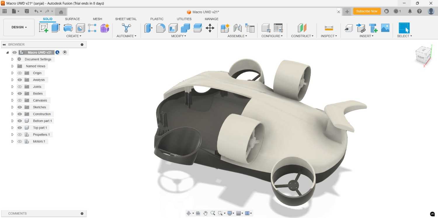
For the Motor and Propeller placement I created the base for the motor where we can fix the motor rigidly.
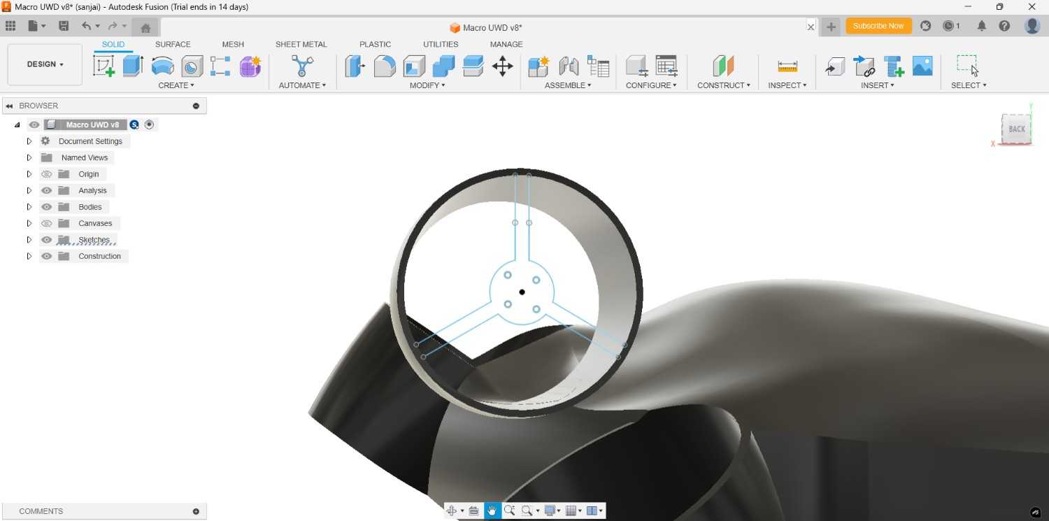
I made it for all the remaining casings also
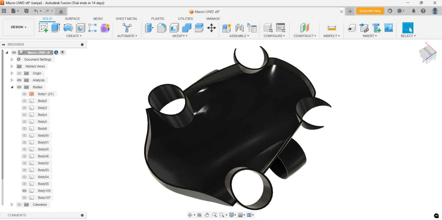
To place the Electronics inside we need the space in the drone inner part, so I drew the spline in one side and did split body by take the spline as cutting tool. Due to the Motor holder placement I drew the spline, because if I cut as straight line it will cut the holder as well, otherwise we can use the line as straight to cut out the body.
After the cutting operation the body only show as cutting block but we need the inner space, so use the shell command to obtain the required space, I gave the thickness 5 mm for rigid body, we can give upto 3 to 5 mm for the strong foundation of our design part.
Though it need to make as much as water proof design, so I draw the rectangle and extend across the body by using the sweep command.

After create it we also did the opposite thing in the other part. So I choose the combine command option, took the sweep done part as the tool body and which one is need to modified to took as target body and cut it out.
Then for the actual fitting I created the slots and extrude it both top and bottom parts with modifing some changes
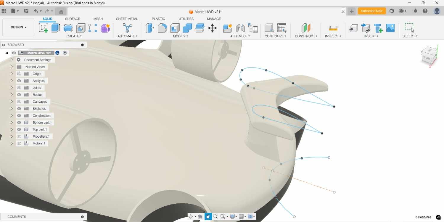
In back end of drone I planned to create the tail like component which is helpful for mitigate the wire risk when the drone is going to far without loosing by tide it completely.
For consider the Fluid dynamic I created it like smooth cure path then extend it by using the loft command.
In my case I planned to 3D print this parts with our Flash forge printer. Due to its volume capacity I should reduce the size to print it, so without scaling it I cut it out into 8 parts. Top part was cut into 4 parts, same as bottom parts cut into 4 parts, now I capable to do the 3D print in our Flash forge 3D printer.
For the lighting adjustment I create the hole infront of the drone
2026 FABLAB
Design Refinement and Scaling of the Underwater Drone
One of the key lessons learned from my previous Fab Academy attempt was the importance of addressing design challenges early in the development process. To avoid repeating the same mistakes, I reviewed all the issues encountered during the earlier underwater drone development and incorporated those lessons into the new design iteration.
Based on the feedback and suggestions provided by my instructor, I decided to simplify the scope of the project and focus on demonstrating the working principle of the underwater drone rather than developing the complete final product. The goal was to create a functional Proof of Concept (POC) that clearly showcases the intended operation and design concept of the system.
Design Objectives
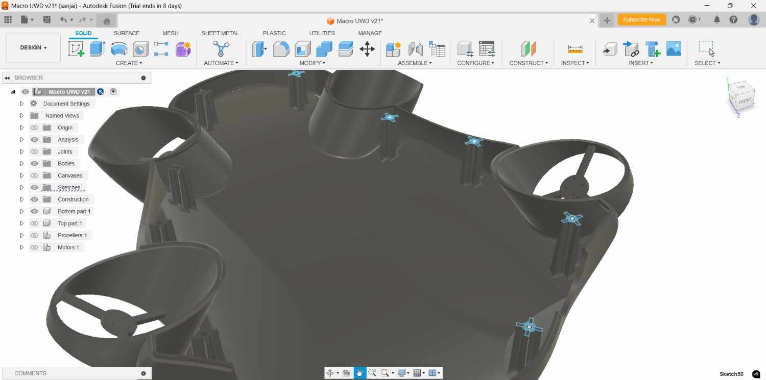
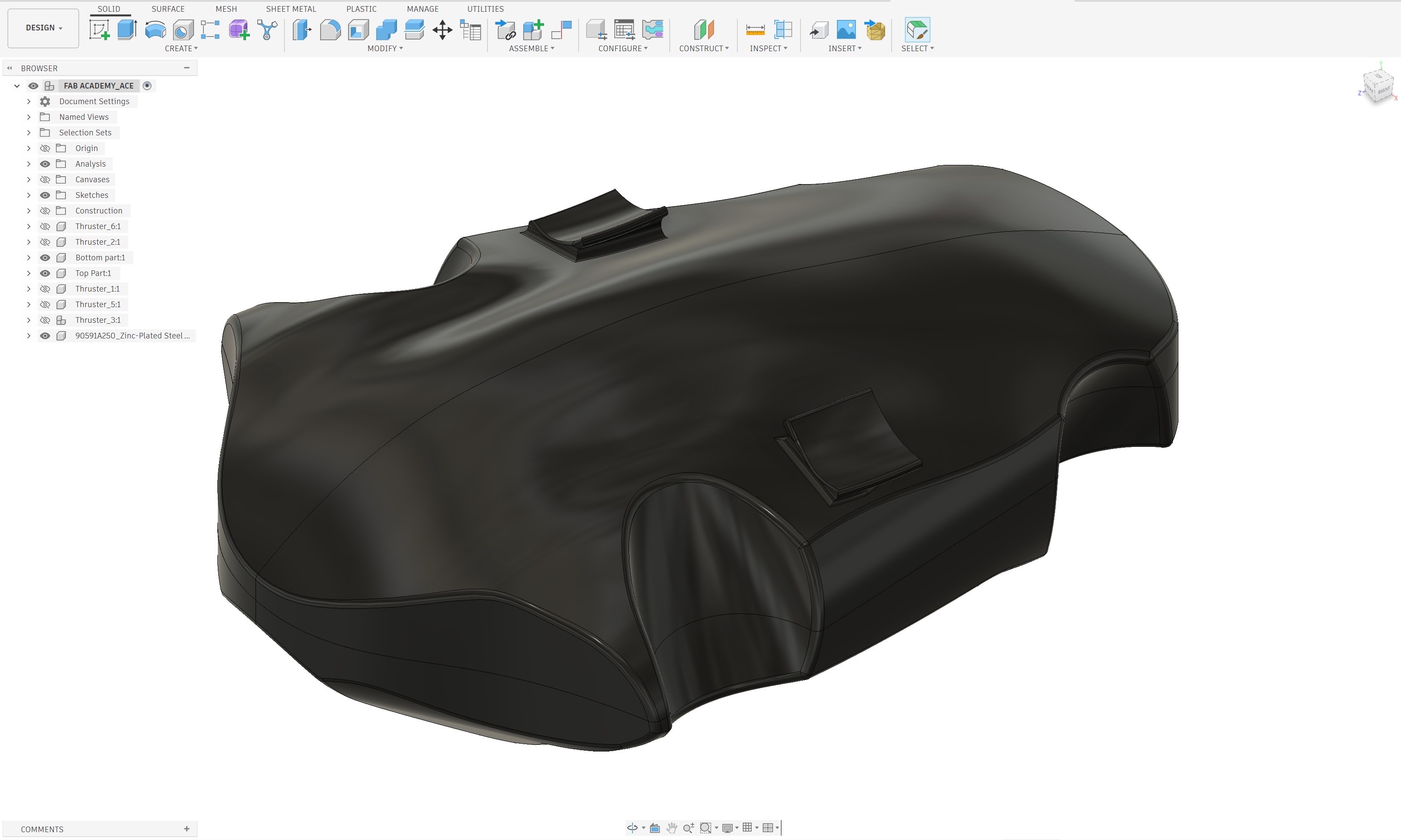
- Improve structural rigidity by designing the drone as a single integrated body instead of splitting it into multiple sections.
- Demonstrate the working concept of the underwater drone through a Proof of Concept model rather than performing full underwater testing.
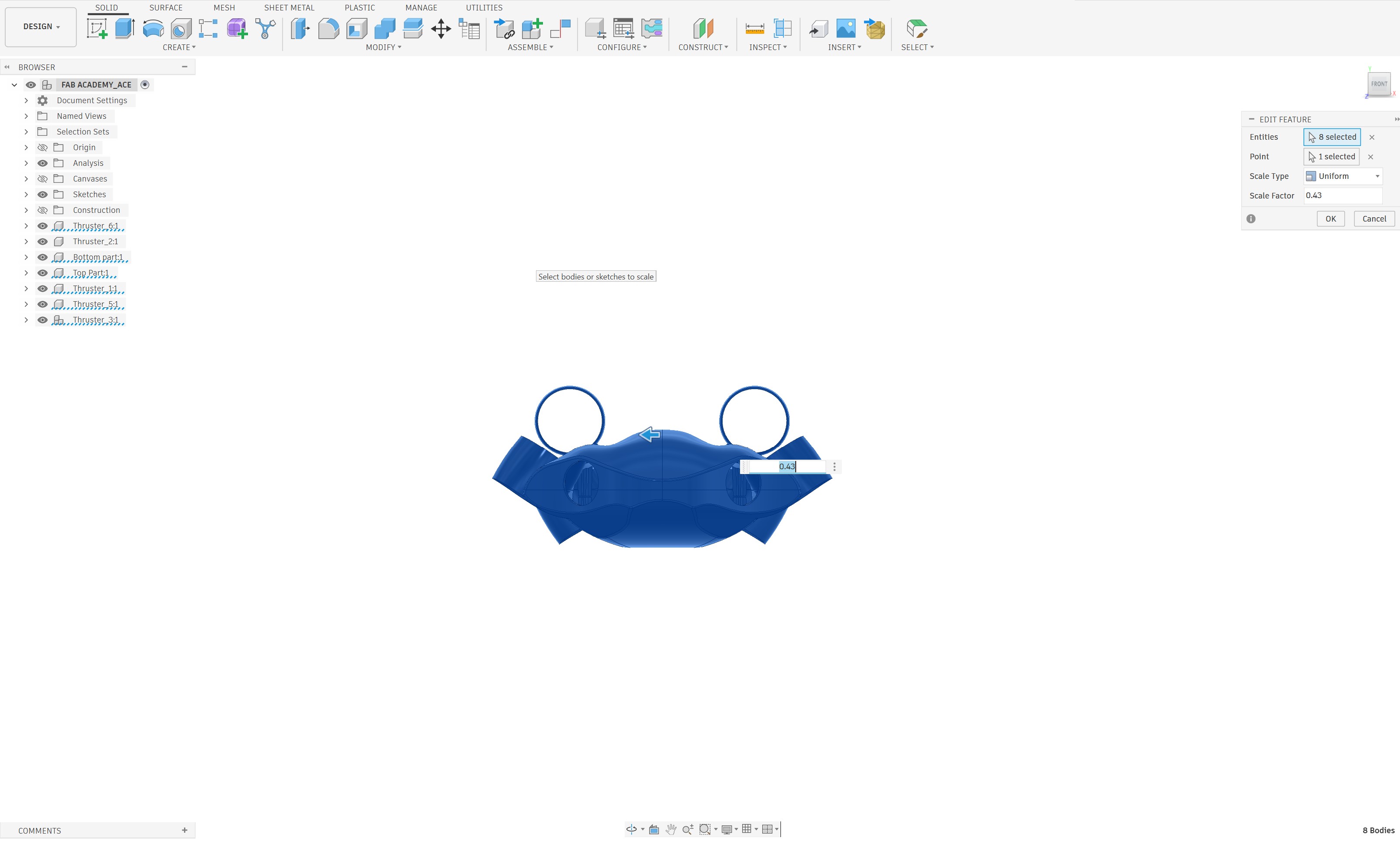
To achieve these objectives, I scaled down the original drone design by a ratio of 2:1 (0.43). After scaling, the overall length of the drone was reduced to approximately 280 mm. This smaller size not only made the design more manageable but also allowed the entire body to fit within the build volume of the available 3D printer. As a result, the drone could be fabricated without dividing the structure into multiple printed components, improving both manufacturing efficiency and structural strength.
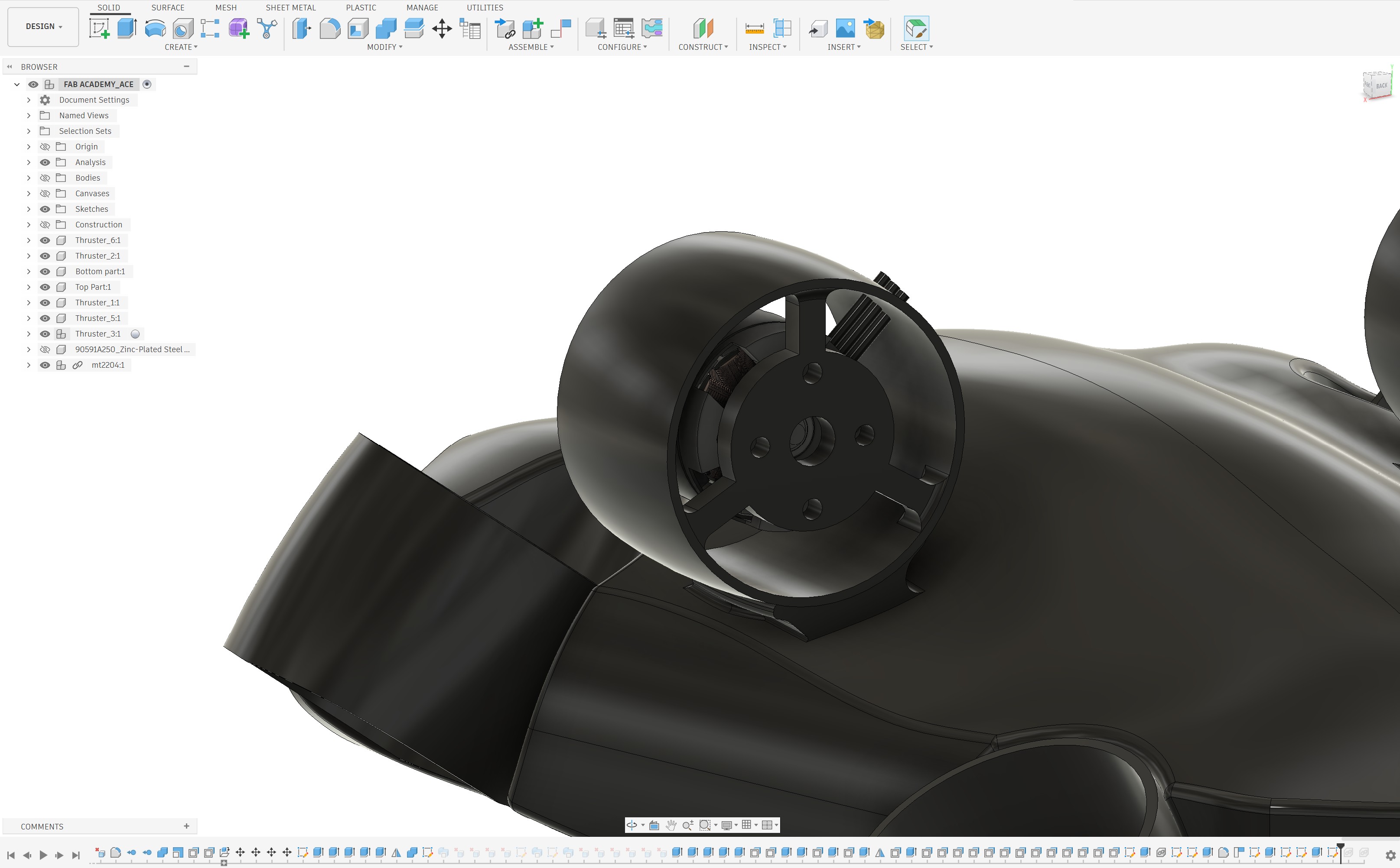
Motor Hub Redesign
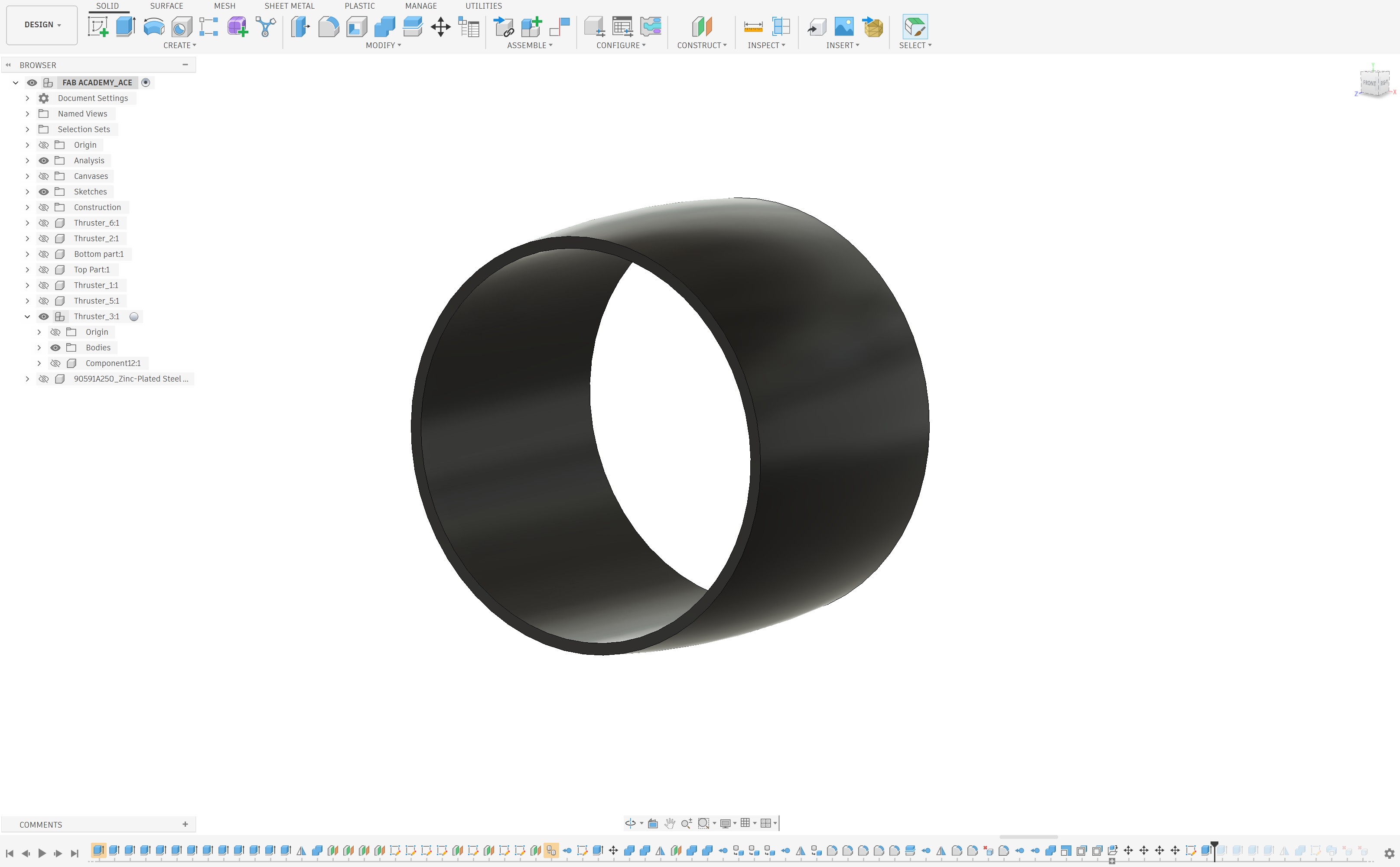
While reviewing the previous design, I identified another issue related to the motor hub assembly. During the earlier fabrication process, a significant amount of support material was required when printing the drone body. This increased print time, material consumption, and post-processing effort.
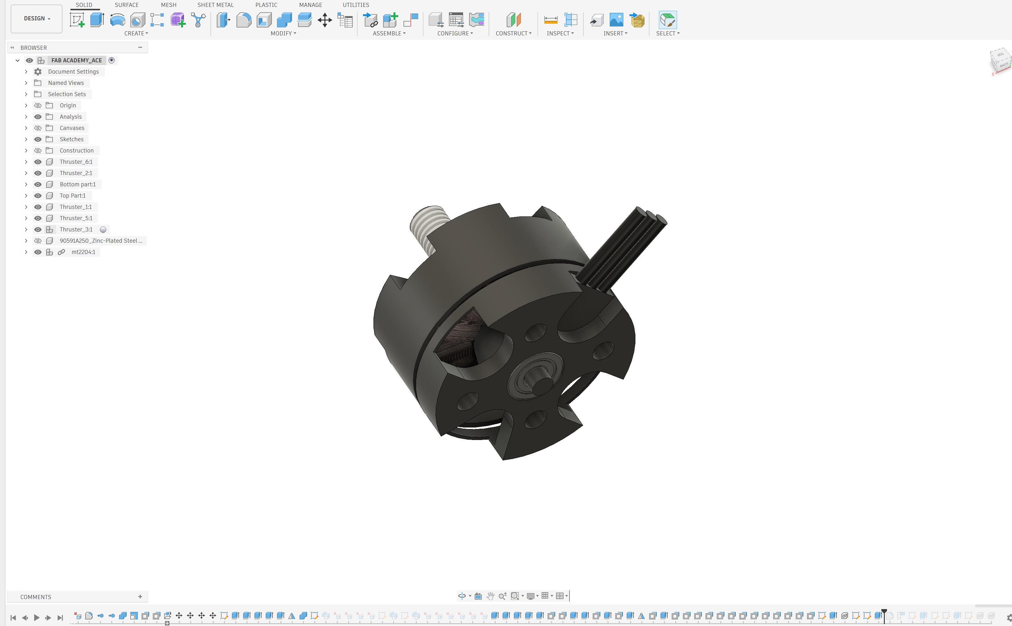
To address this challenge, I redesigned the motor hub system and separated the motor mounting components from the main drone body. This modular approach significantly improved the printability of the design while reducing the amount of support material required during fabrication.
After several design iterations and adjustments, I successfully separated the motor mounting assemblies from the drone body and optimized their geometry for manufacturing. Additional modifications were also made to the top-center motor hub to ensure proper positioning and alignment within the overall structure.
Motor Selection and Mounting Design
For this scaled-down prototype, I selected the MT2204 2300KV brushless motor. To accommodate this motor, the motor mounting interface was redesigned according to the motor's mounting hole pattern and hole diameter specifications. This ensured proper alignment, secure fastening, and compatibility with the selected propulsion system.
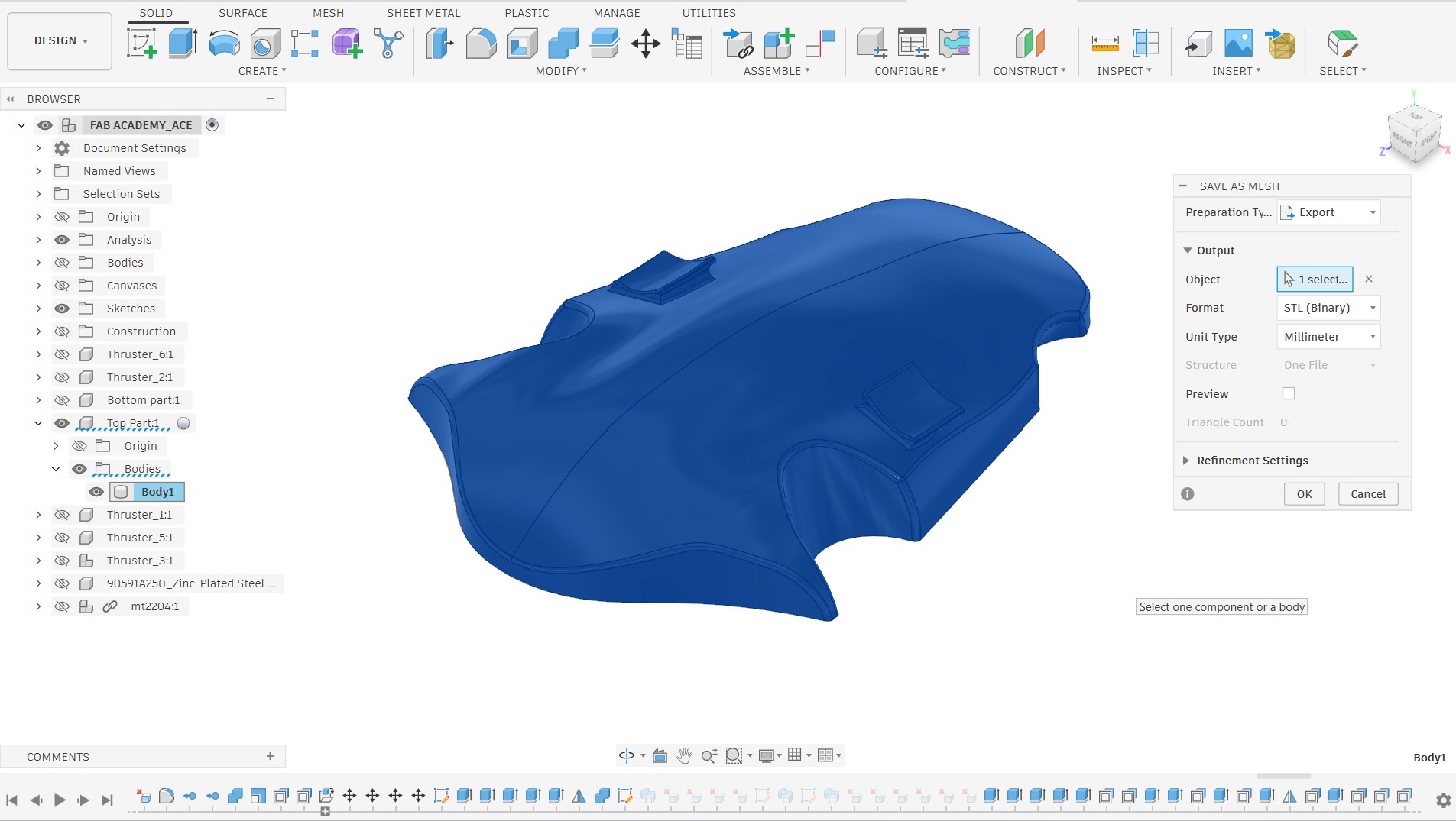
Once all design modifications were completed, each component was exported as an individual STL file for fabrication and further testing.