Computer Controlled Cutting
Overview of week 3
Group Assignment
- Do your lab's safety training
- Characterize your lasercutter's focus, power, speed, rate, kerf, joint clearance and types.
- Document your work to the group work page and reflect on your individual page what you learned.
Individual Assignments
- Design, lasercut, and document a parametric construction kit, accounting for the lasercutter kerf, which can be assembled in multiple ways.
- Cut something on the vinyl cutter.
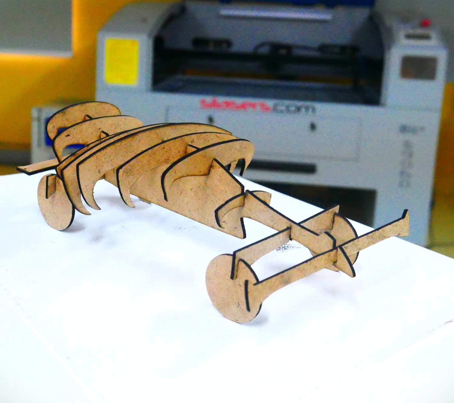
Hero Shot

Individual Assignment :
Laser Cutter
- Laser cutting is a technique that utilizes a laser beam to cut through materials while commonly employed in industrial manufacturing. The process involves guiding a high-power laser through optical components to achieve precise cuts.
- In our lab, we use a CO₂ laser, which is specifically designed for cutting non-metal materials. We used the SIL laser cutting machine in our lab.
Specification
- Cutting Material : - Acrylic, MDF...etc
- Laser Power : 100 Watt
- Laser Type : CO₂ Sealed Glass Laser Tube
- Cooling Method : - Water Cooling
- Engraving Speed : - 0-64000 mm / min
- Working Voltage : - AC 230 V + 10%
- Positioning Accuracy : - 0.1 mm ( MAX )
- Cutting Speed : - 0~30000 mm / min
- Working Area : 600 x 900 mm
- Temperature Deg Celsius : - Temp 0 c ~ 45 c
- Control Software : Laser CAD
- Supported File Formats: DXF, AI, PLT, BMP, JPG, PNG, etc.
Kerf
Kerf refers to the width of material removed during a cutting process, such as laser cutting, plasma cutting, or waterjet cutting. It depends on factors like the laser beam diameter, material type, and cutting speed.
Focus
Focus in laser cutting refers to the precise positioning of the laser beam's focal point for optimal cutting accuracy. Proper focus ensures minimal kerf width and clean edges.
Flatfab
FlatFab is a 3D design software that helps create flat, interlocking parts for laser cutting, CNC routing, and fabrication. It allows users to design complex 3D structures using 2D flat panels, which can be assembled without additional fasteners. The software automatically generates cut-ready plans with joint details.
As a design engineer, I am highly enthusiastic about using this software to create models based on my concepts with minimal effort. It is an excellent choice for creative thinkers to bring their ideas to initiate that without requiring extensive design knowledge.
The software's tools are well-suited for complete beginners, and its user-friendly interface enhances the overall design experience.
After exploring the software's modeling capabilities, I was inspired to design the structure of an F1 car, I barely design the outlayer by using the external image as use as reference.
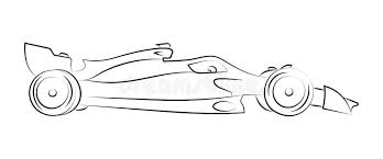
I began by designing the main body of the F1 car, followed by the outer frame and wheels. However, achieving uniformity in the wheel design proved to be challenging. While the software is effective, it occasionally experiences lags when attempting to align designs precisely with the axis.
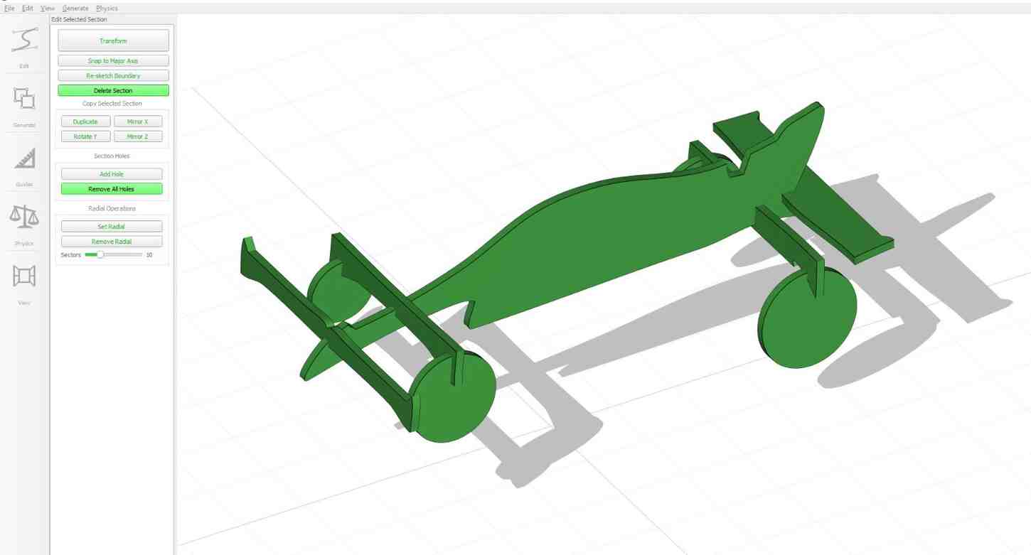
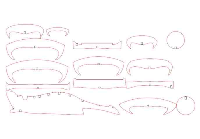
I then converted the design into a DXF file for the next set of operations. However, due to performance lags affecting the design process, I remodeled and adjusted its dimensions using Fusion 360 for better precision and efficiency.
Fusion 360
Fusion 360 is a cloud-based 3D CAD, CAM, and CAE software developed by Autodesk. It integrates design, simulation, manufacturing, and collaboration tools into a single platform, making it ideal for product development. Fusion 360 supports parametric, direct, freeform, and mesh modeling, along with generative design, rendering, and simulation capabilities. It is widely used in mechanical engineering, industrial design, and prototyping due to its user-friendly interface and advanced features.
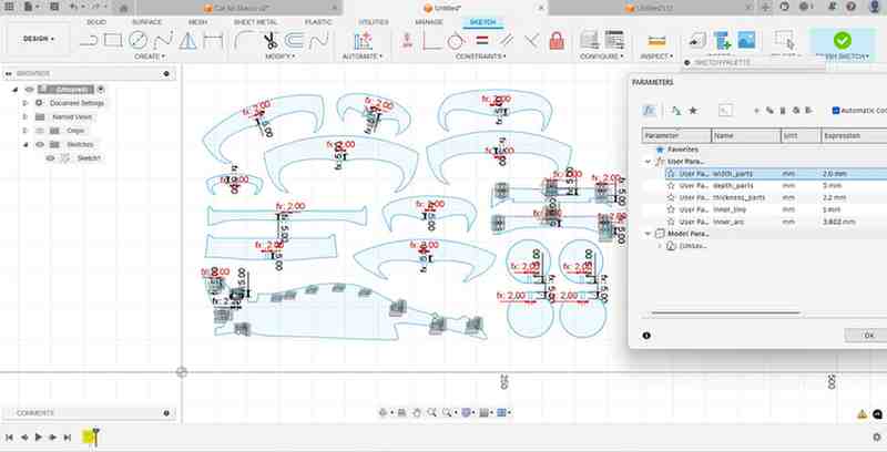
I am familiar with Fusion 360 and used the sketching tool to create a design based on my own drawing for cutting the workpiece material.
Using Fusion 360, I defined parameters for the joint parts to ensure they aligned with the other components. I utilized parametric modeling to enable easy design modifications, allowing for future adjustments as needed.

I then optimized the arrangement of components to minimize material waste during the cutting process. However, I encountered an issue with constraints. I had forgotten to set them properly for reiteration, which led to errors in the parametric parameters. Ater I rework on it fix the errors which is faced.

Cutting Process:
I set up the laser cutting machine and selected the appropriate material thickness based on the dimensions of my design. I chose MDF sheet as the material to achieve the desired output and it is the low cost material compared to the Acrylic sheet.
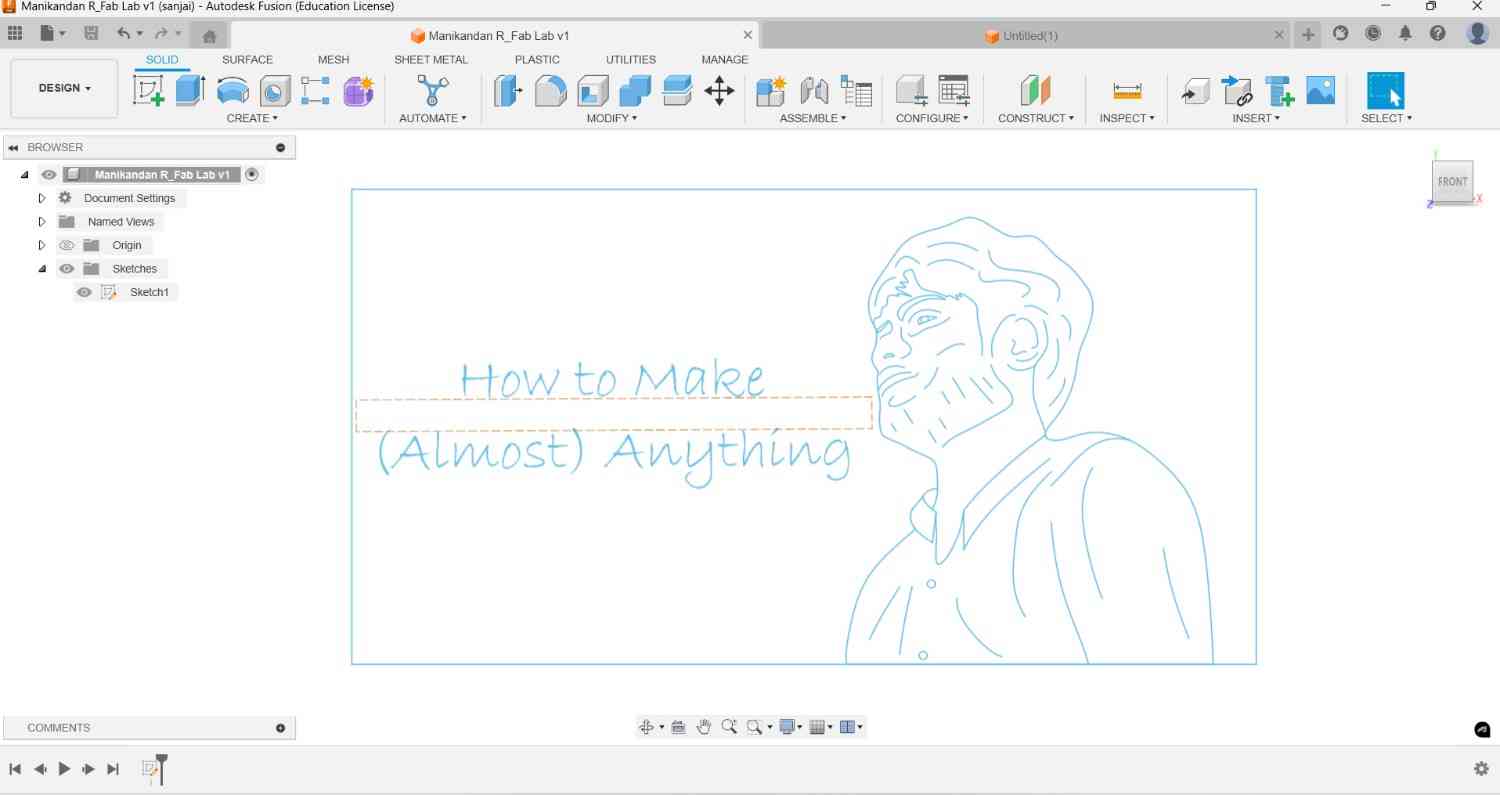
Opened the LaserCAD software and imported my DXF file. Then, I defined the necessary cutting areas and adjusted the parameters according to the material thickness.
To set the origin as the starting point for the cutting process and performed a pre-check using the box tool to verify that the dimensions were accurate.
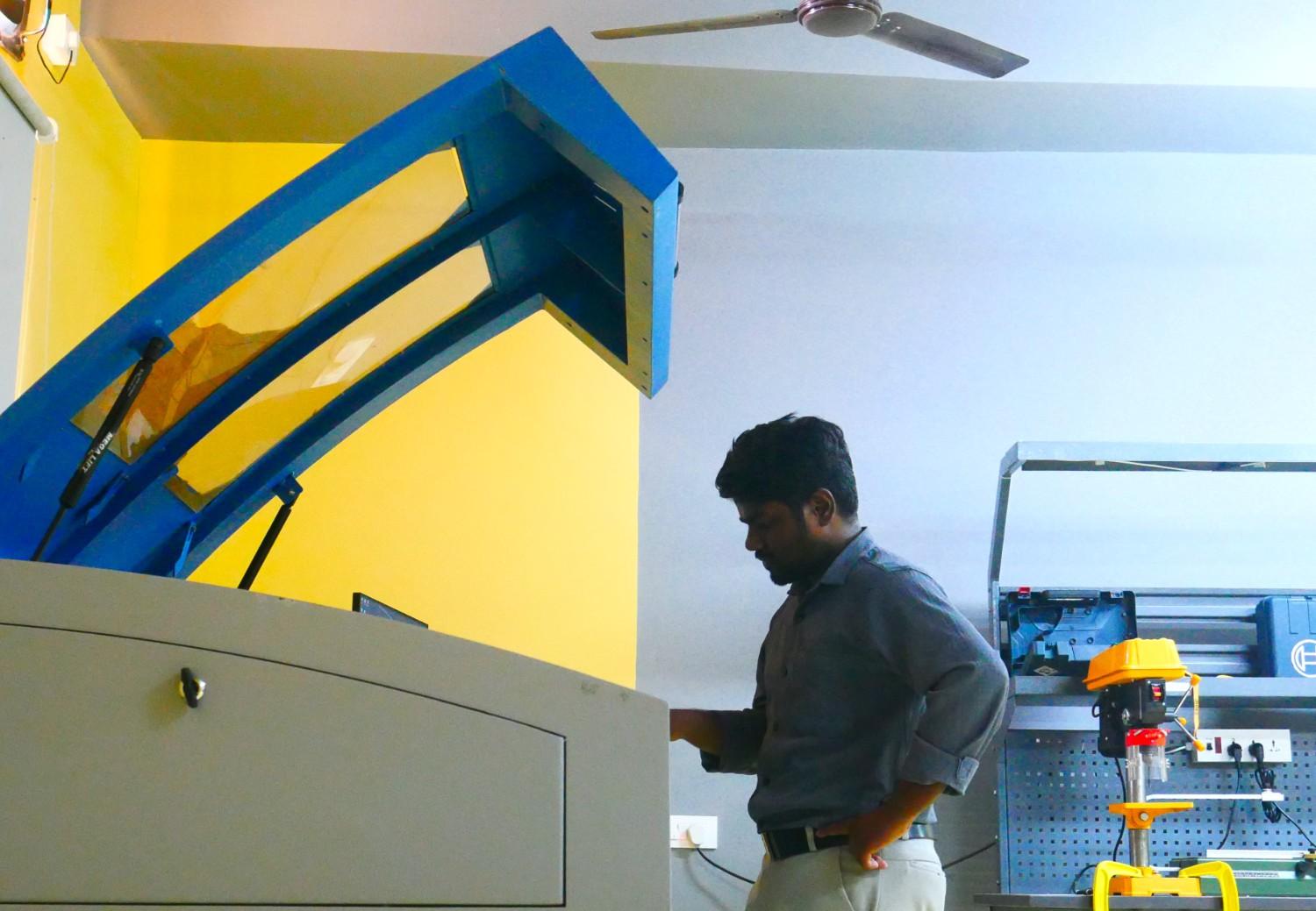
Then closed the protective shield, turned on the laser, and carefully observed the cutting process to ensure precision and quality.
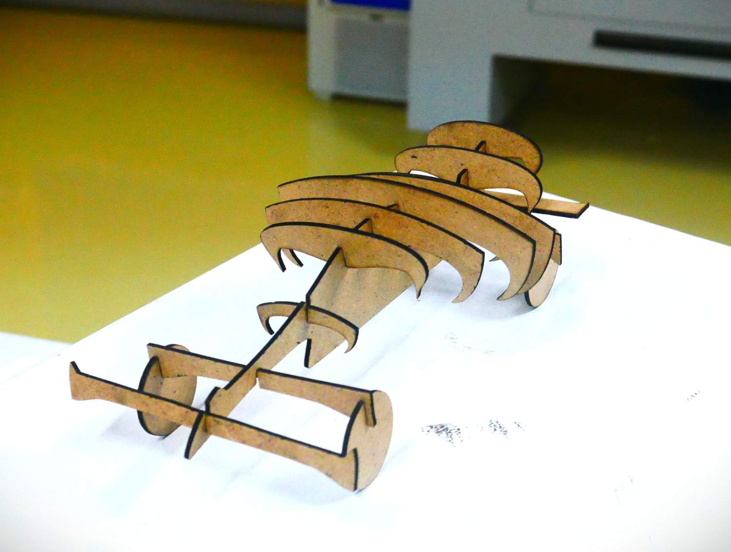
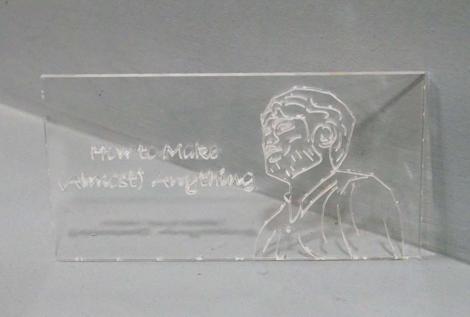
After completing the cut, I turned off the laser, opened the protective door, and cleaned the cutting area. Then carefully removed the cut pieces to verify that they were fully and accurately cut.
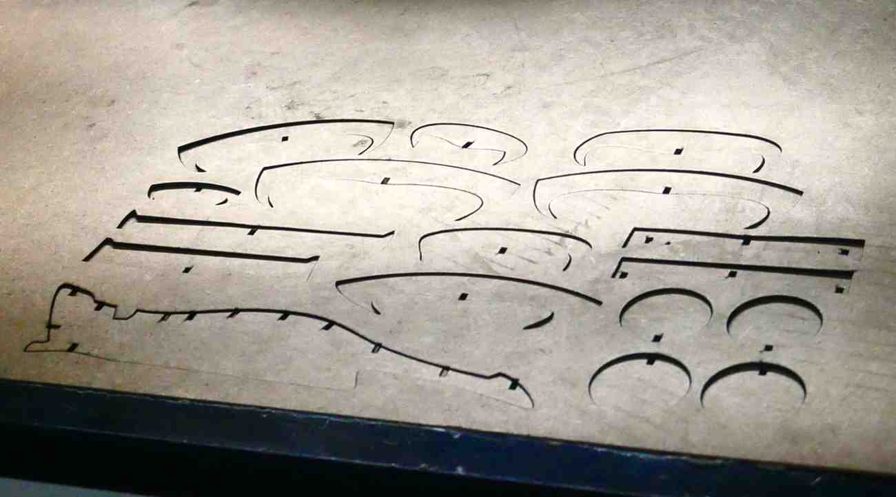
Assembled the cut pieces, aligning them according to their designated positions.
Vinyl Cutter
- A Vinyl cutter is a computer-controlled machine used to cut designs from vinyl sheets. It operates like a plotter but uses a blade instead of a pen to cut shapes, letters, and patterns. Vinyl cutters are commonly used for making stickers, decals, signs, and heat transfers for textiles. Precision cutting allows for intricate designs without manual effort. Advanced models can also handle materials like paper, cardstock, and thin plastics.
- In our lab, we use the Skycut cutting plotter.
Specification
- Model : Skycut C24 (2feet)
- Drive type : Stepper motor
- Media loading Size : 720mm
- Cutting Size : 610mm
- Max Cutting speed : 600mm/sec
- Max Cutting force : 800gm
- Auto Contour Cut : Camera
- Interface : USB Flash/USB cable
- Power : 24V, 1.5A Less than 100Watts
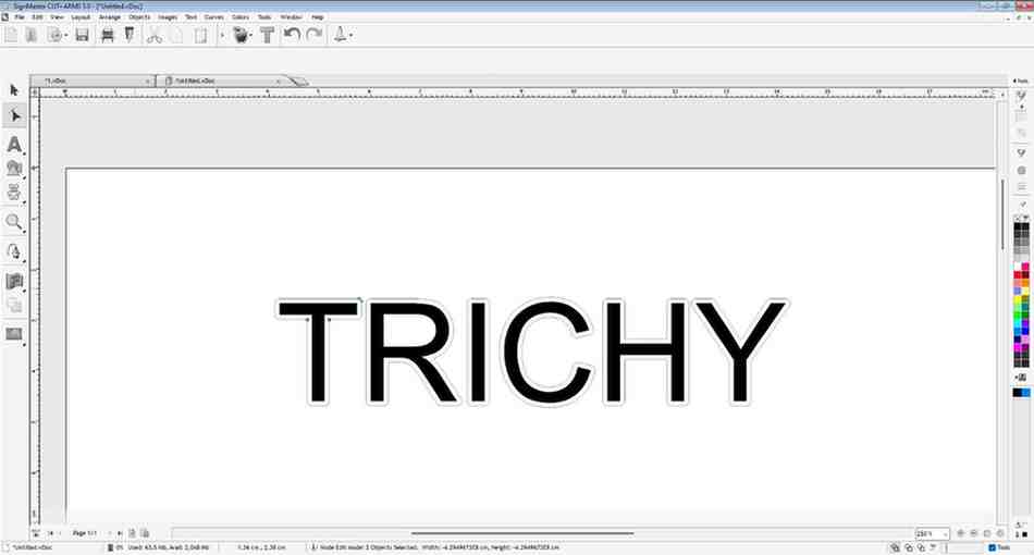
SignMaster
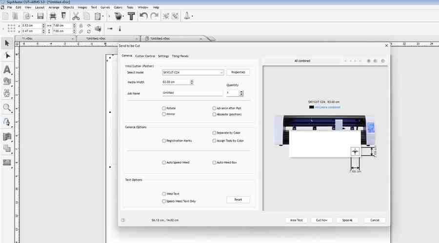
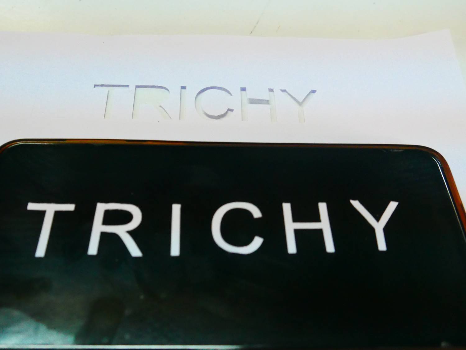
Using the SignMaster, I connected the vinyl cutter and began exploring its interface by watching tutorials. Then performed a simple text TRICHY for cutting test to ensure proper functionality.
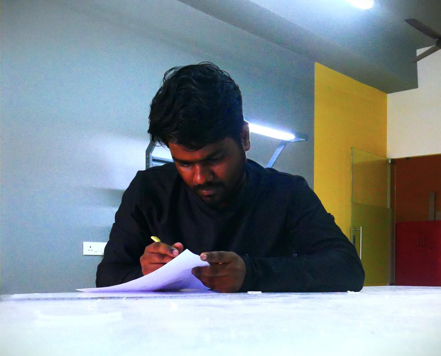
I then set up the vinyl cutter and loaded an A4 sheet for a test run before proceeding with the actual vinyl sheet.

Used a 30-degree blade to cut the paper and adjusted parameters such as speed and force based on the paper's toughness to prevent tearing and excessive blade wear.
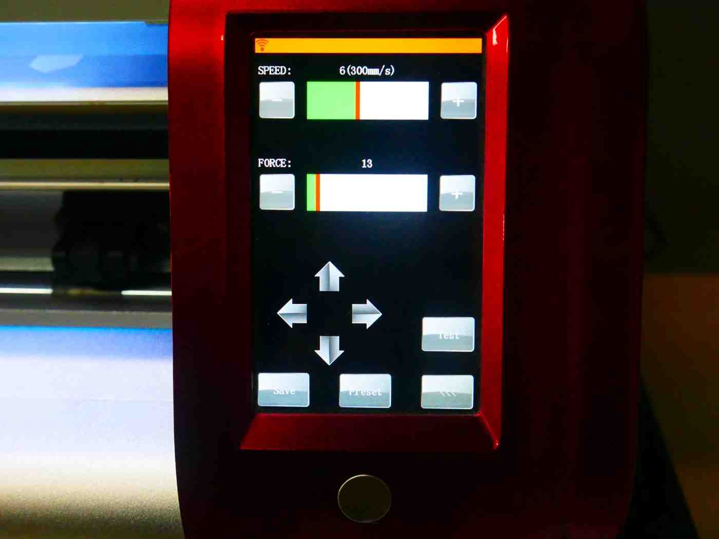
After performing 2 to 3 test cuts, I fine-tuned the parameters to achieve a precise cut on the A4 sheet. Then carefully removed the cut pieces from the parent sheet.
Next, I planned to perform the same activity using a vinyl sheet. I selected a blue-colored sheet and set up the vinyl cutter for the cutting process.
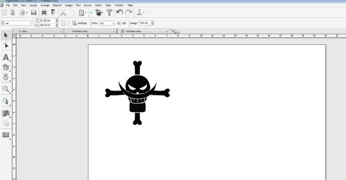
I initially searched for an image without a specific idea in mind. Eventually, I decided to cut the One Piece anime pirate logo and choose the Whitebeard flag as inspiration for its iconic design.
I downloaded the desired logo and converted it into an
SVG file. After importing it into the software, I made the necessary adjustments to align with my desired output design.