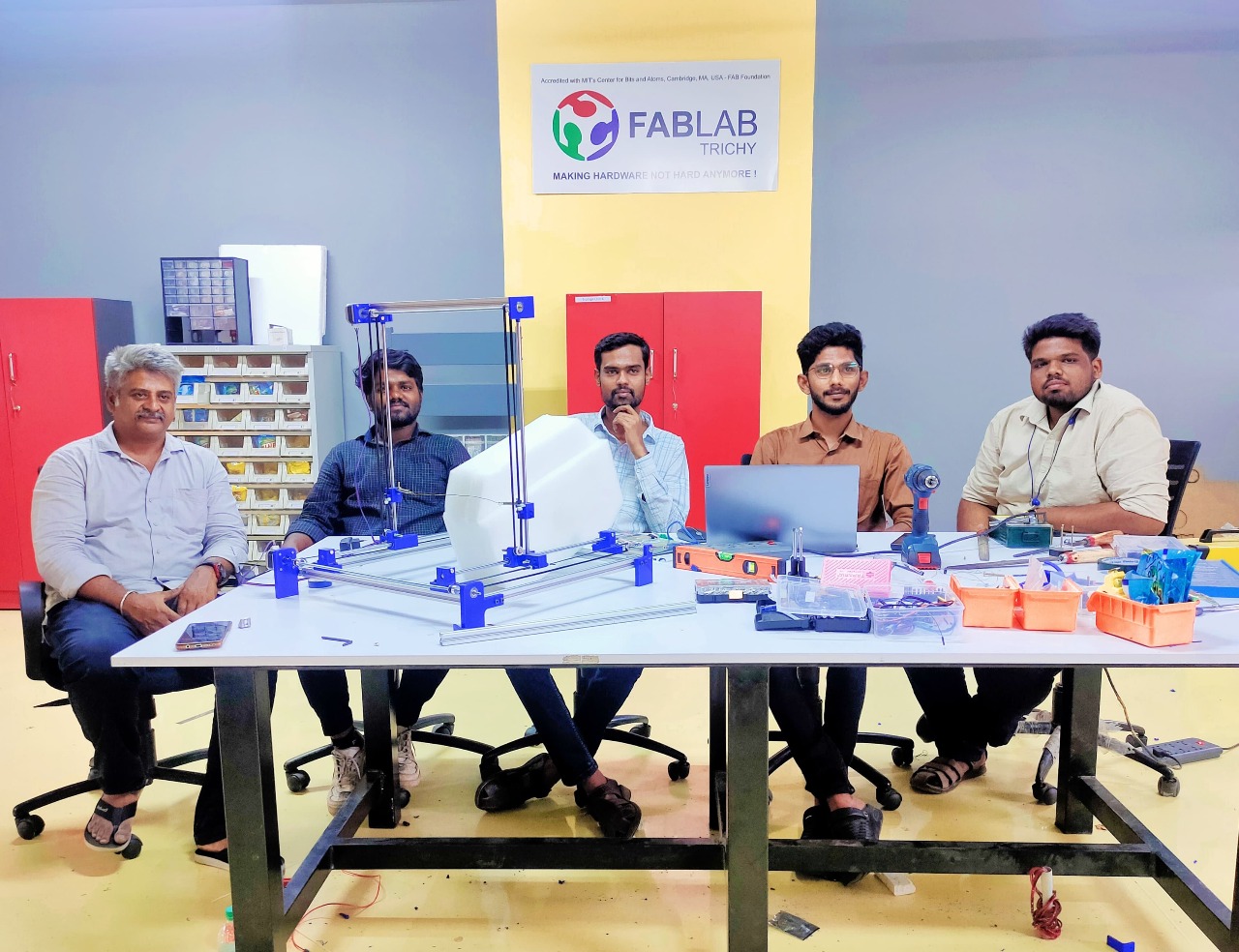
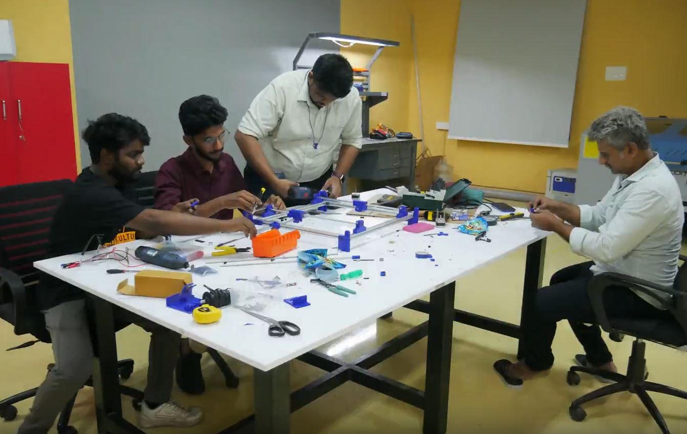
Our Group Assignment
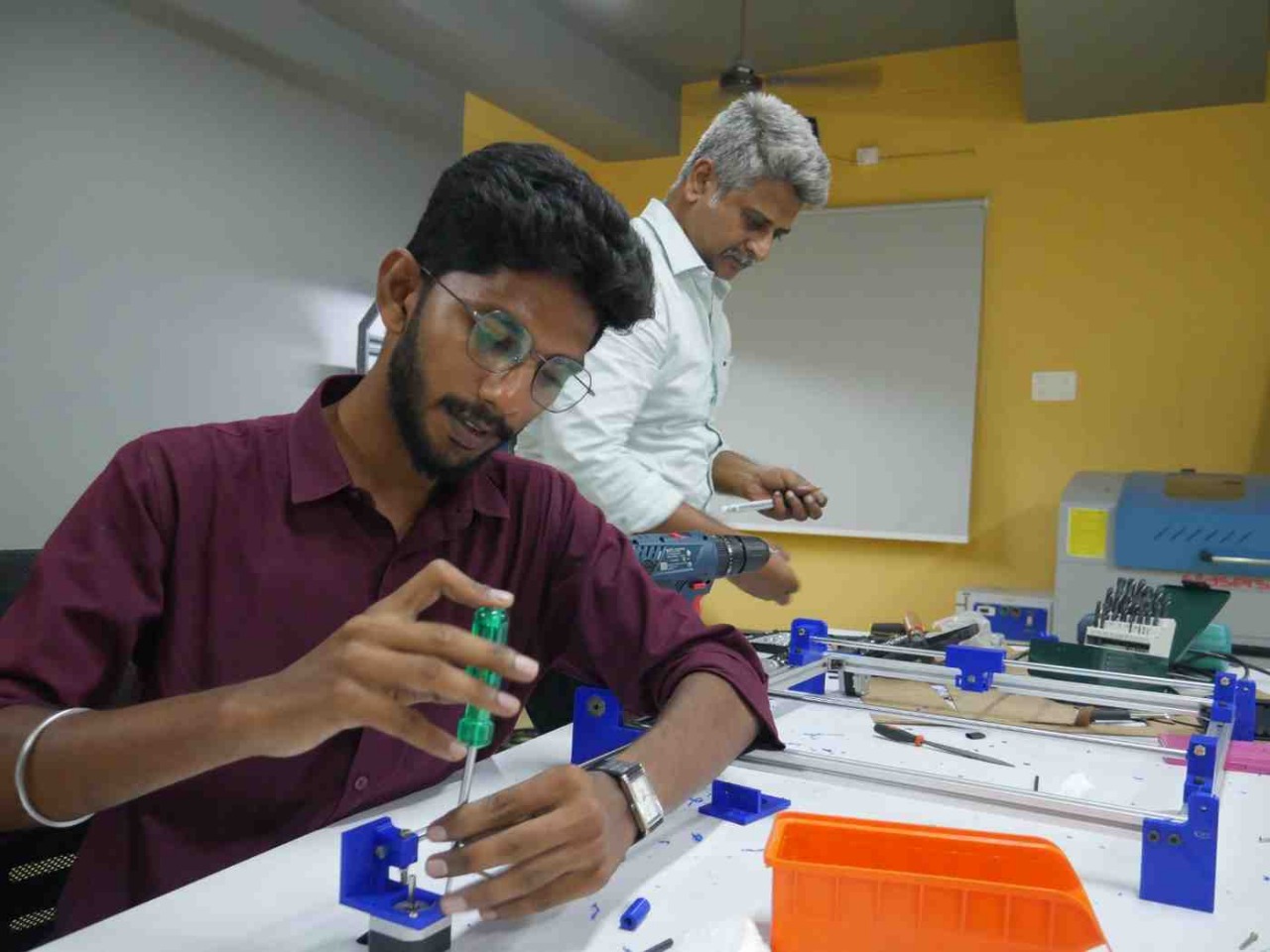
As part of the group assignment, we collaboratively designed and built a machine that incorporated a mechanical structure, actuation system, automation, and a specific application. The project involved brainstorming concepts, planning the machine architecture, allocating tasks among team members, designing mechanical components, fabricating parts, assembling the system, and testing its operation. Initially, the mechanical system was operated manually to verify its functionality. We then integrated motors, control electronics, and programming to actuate and automate the machine. Through this process, we gained practical experience in machine design, mechanical fabrication, motion control, system integration, teamwork, and project management. The assignment enhanced our ability to design, build, troubleshoot, and improve complete electromechanical systems from concept to implementation.
Individual assignment:
Documented my individual contribution for Mechanical Design, Machine Design
My Role is Components Procurement Machine AssemblyDesign focuses on creating and detailing parts, assemblies, and systems that meet functional requirements.
Machine Design is a subset of mechanical design, specifically targeting the creation of complete machines.
It involves material selection, calculations for strength, motion, and durability.
Both require understanding forces, stresses, motion, and efficiency.
Goal: Build reliable, cost-effective, and user-friendly mechanical solutions.
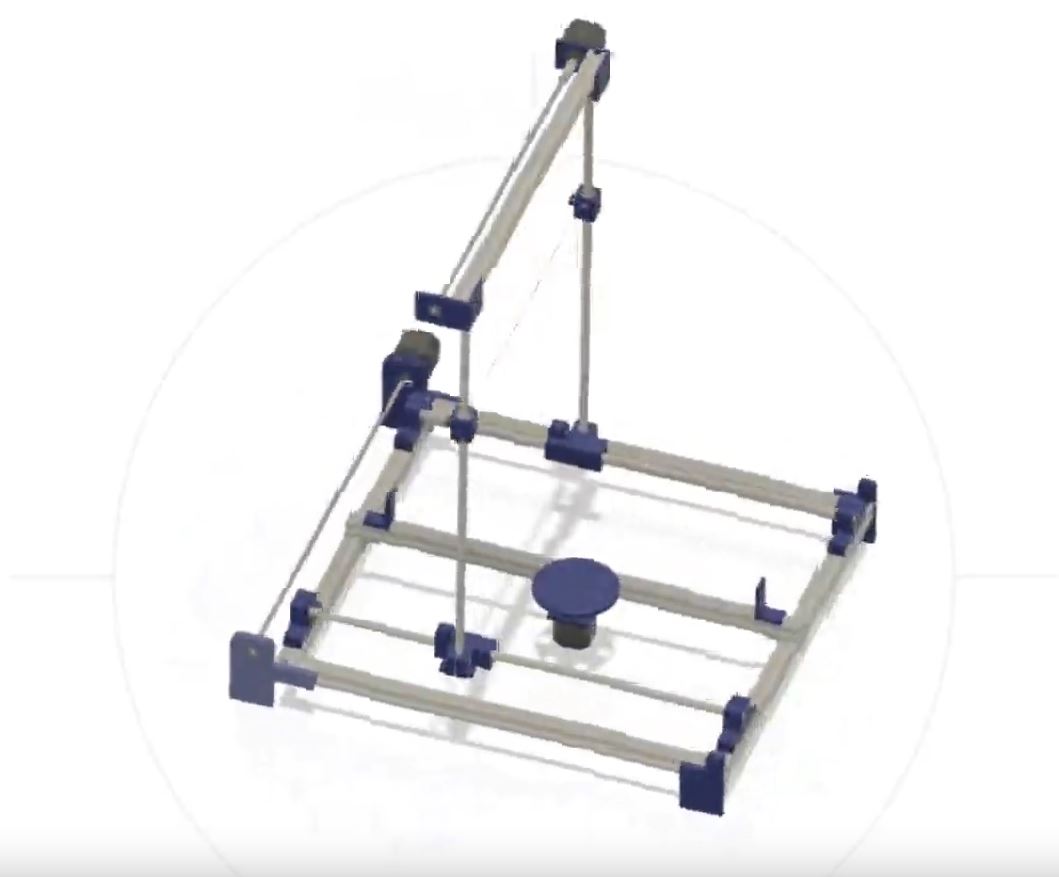
DIY 3-Axis Hot Wire Foam Cutter For the Machining week
IntroductionThe demand for complex foam cutting has increased in industries like packaging, aerospace, architecture, and RC modeling. Traditional single-axis cutters are limited to straight-line cuts. This project aims to design and build a 3-axis CNC- controlled hot wire foam cutter for cutting complex 2.5D profiles, airfoils, and custom shapes from thermoplastic foams like EPS and XPS.
Foam Cuttting Machine usageFoam cutting machines are used to shape, trim, and carve different types of foam like PU, EPS, and EPE.
They help create precise parts for packaging, insulation, signage, and models.
Machine is CNC controlled for complex designs.
Hot wire, blade, and laser are common cutting methods depending on foam type.
They reduce material waste and improve production speed and accuracy.
Widely used in industries like construction, automotive, furniture,prototyping.Education,hobby and ent
ertainments
A Hot Wire Foam Cutter is a simple yet effective machine that uses a resistive wire heated by electricity to cut through foam like EPS or XPS
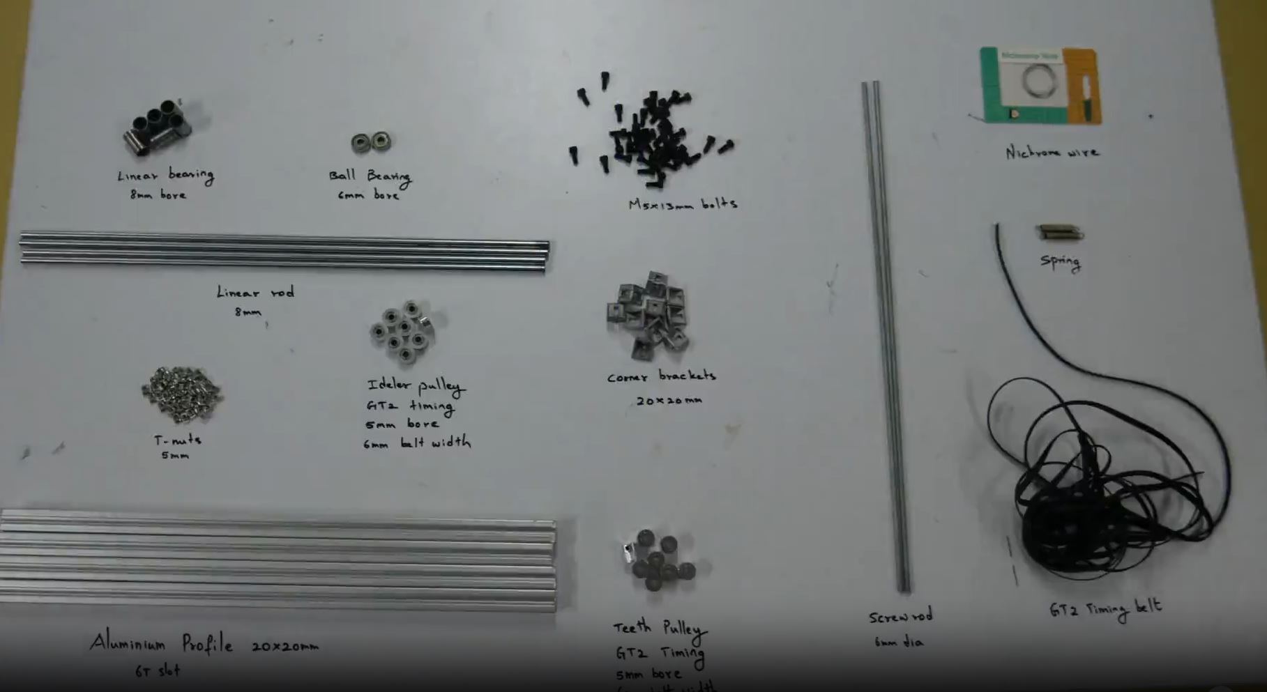
| 🔌 Component | Specification | Qty |
|---|---|---|
| Nichrome Wire | 0.3–0.5 mm | 1 loop (approx. 40–60 cm) |
| Aluminium profile | 10 feet length | 1 no |
| 8mm linear rods | 19 inches length | 4 |
| linear bearing | 8mm dia | 8 no |
| screw rod | 600px dia 3 feet | 1 no |
| gt2 timing belt | 3feet lkength | 2 no (optional) |
| t-screw | 6mm dia | 24 no |
| gt timing pulley | 8mm bore | 3 no |
| normal pulley | 8mm bore | 2–3 |
| ball bearing | 6mm bore | 2 no | Nichrome | 3mm wire | 1 meter |
Phase 1: Planning & Layout
Define Cutting Area Dimensions:
Example: 600mm (X), 400mm (Y), 300mm (Z).
Consider foam block size and tool reach.
Design the Frame:
Use T-slot aluminum
Sketch your gantry-based or moving-bed layout
. List Tools Required:
Drill, hacksaw or metal cutter, screwdriver set, multimeter, soldering iron, etc.
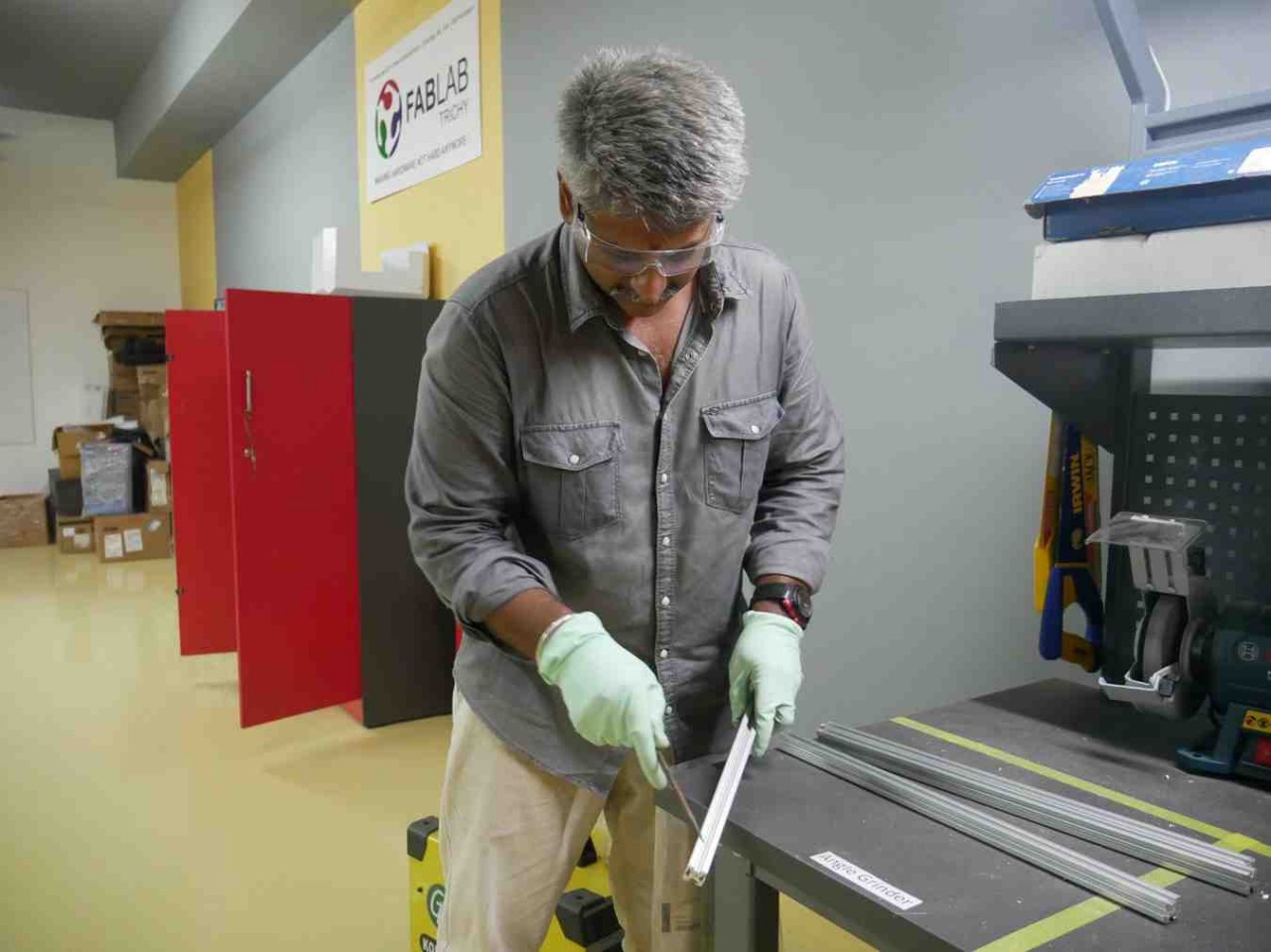
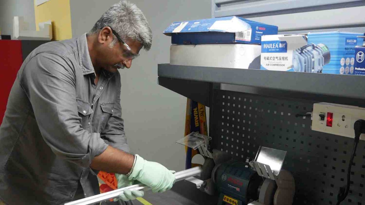
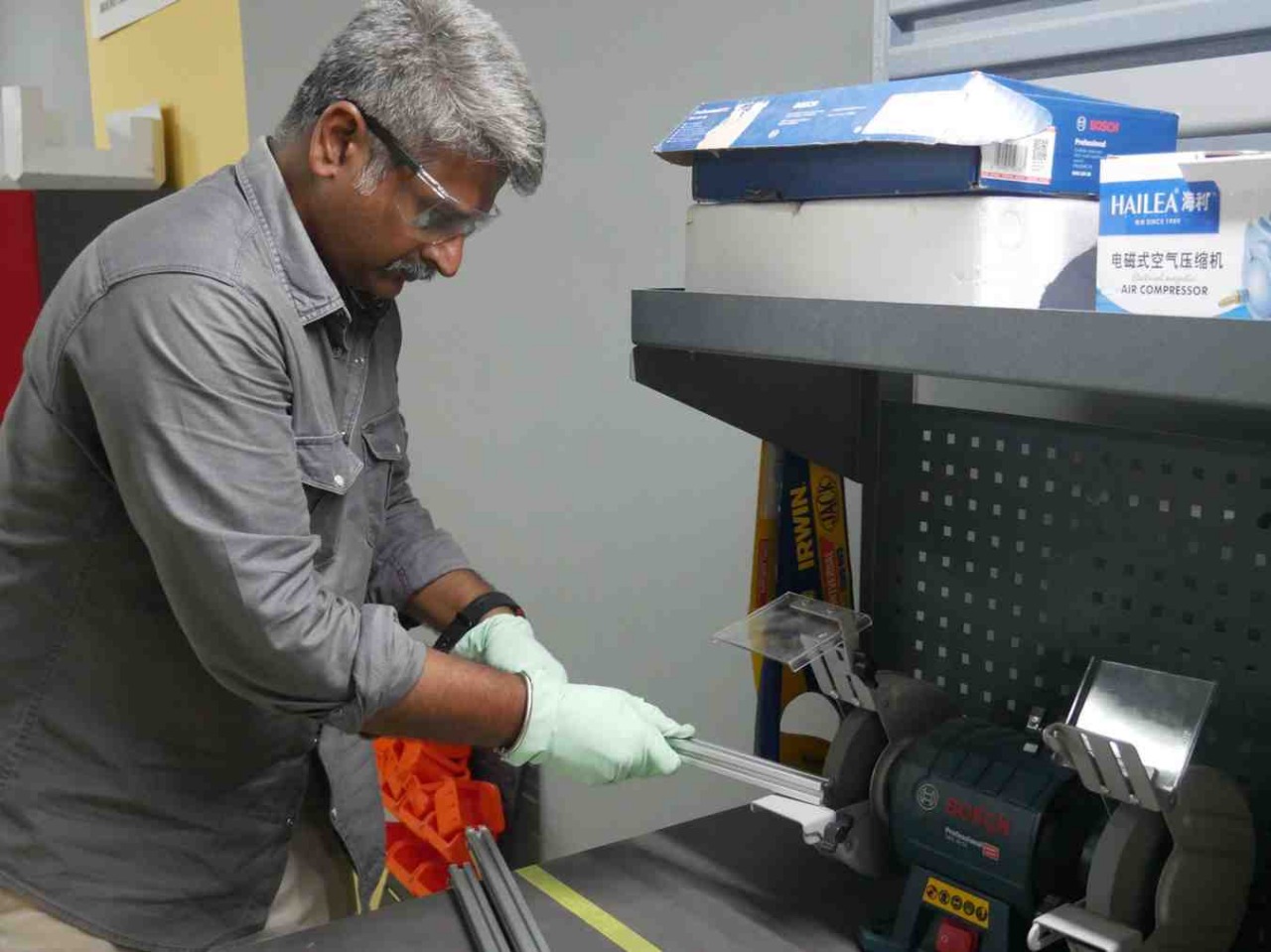
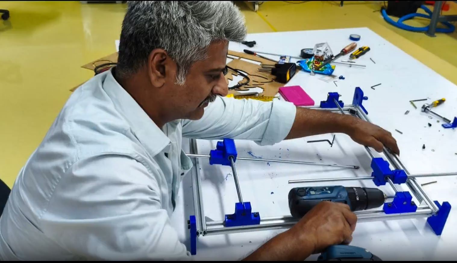
Phase 2: Mechanical Fabrication
1. T-slot aluminum Frame Construction:
Cut T-slot aluminum extrusions to the required lengths for the base and vertical supports.
Use corner brackets or L-joints to connect and square the frame.
Slide T-nuts into the slots to fasten components securely with bolts.
Assemble the base frame first, then attach vertical and cross members.
Ensure the entire structure is level, square, and rigid before mounting any motion components.
Cut and assemble the base and vertical supports.
Ensure 90° alignment using corner brackets or L-squares.
2. Mount Linear Rails:
Mark precise alignment points on the frame for each axis.
Secure the linear rails or support rods using clamps, brackets, or screws.
Attach linear bearings (e.g., LM8UU or V-slot wheels) to the moving gantry or carriage.
Slide the bearings onto the rods to test smooth movement and adjust alignment.
Tighten all fasteners after verifying straight, friction-free motion.
Attach rails or guide rods for X, Y, Z axes.
Install linear bearings
3. Mount screw rod:
Secure the stepper motor on a mounting bracket aligned with the axis.
Attach a shaft coupler to the motor shaft.
Insert the screw rod (lead screw or threaded rod) into the coupler and tighten.
Mount bearing supports at both ends of the screw rod.
Ensure the rod is straight and rotates smoothly without wobble or binding.
Fix stepper motors with brackets.
Connect GT2 belts or lead screws with pulleys/couplers.
Align idlers or bearings to ensure smooth motion.
4. Z-Axis Wire Arms:
Build two sliding arms that can move up/down or tilt.
Stretch nichrome wire between them with spring tension.
lace a properly sized thermocol block securely on the cutting bed or between wire arms.
Power on the machine and set the wire temperature using the PWM controller.
Load a test G-code file for a simple shape (e.g., square, circle, or airfoil).
Run the cutter and monitor for smooth movement and clean, smoke-free cuts.
Inspect the cut quality and adjust speed, wire tension, or temperature as needed.

Analyze and Solve Technical Problems
| # | Problem | Solution |
|---|---|---|
| 1 | Component Compatibility Issues Some sourced components (like lead screw nuts and motor couplings) had mismatched dimensions compared to the mechanical design files. |
Verified mechanical drawings and adapted the mounting plates using spacer shims and custom brackets to ensure alignment without redesigning major parts. |
| 2 | Axis Misalignment During Assembly Minor misalignments in the X and Y-axis motion due to frame tolerances and improper tightening of brackets. |
Used a square, dial gauge, and iterative tightening to re-align the frame and linear rails. Adjusted motor and screw mounts for minimal play and ensured smooth, backlash-free movement. |
| 3 | Wire Tensioning & Sagging The hot wire, if not properly tensioned, caused inconsistent cuts due to sagging at high temperatures. |
Integrated a spring-based tensioning mechanism to maintain consistent wire tension during heating and movement. |
| 4 | Stepper Motor Vibration Excessive vibration in stepper motors during rapid movement affected precision. |
Checked motor current settings, added rubber dampers, and isolated the motor mounts from the frame to absorb vibrations. |
Improvement Steps Based on Assembly Experience
| Area | Current Practice / Observation | Issue | Improvement Step |
|---|---|---|---|
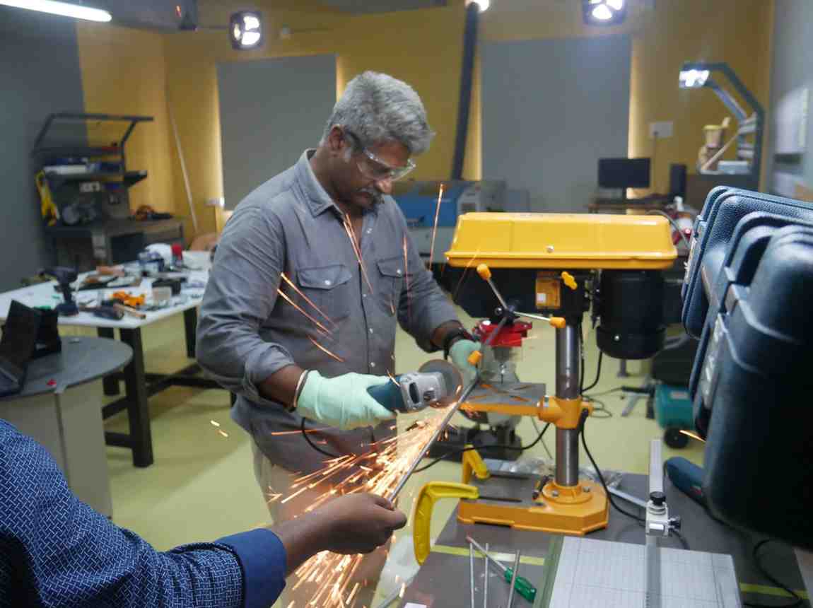
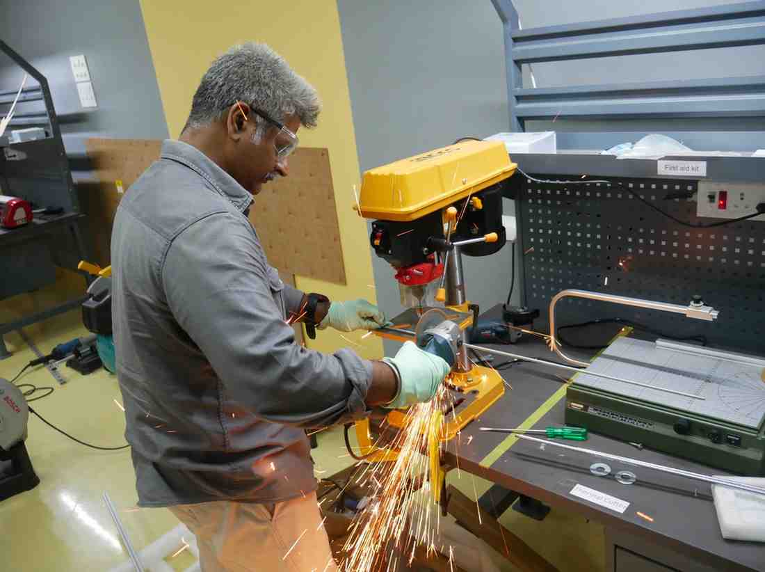
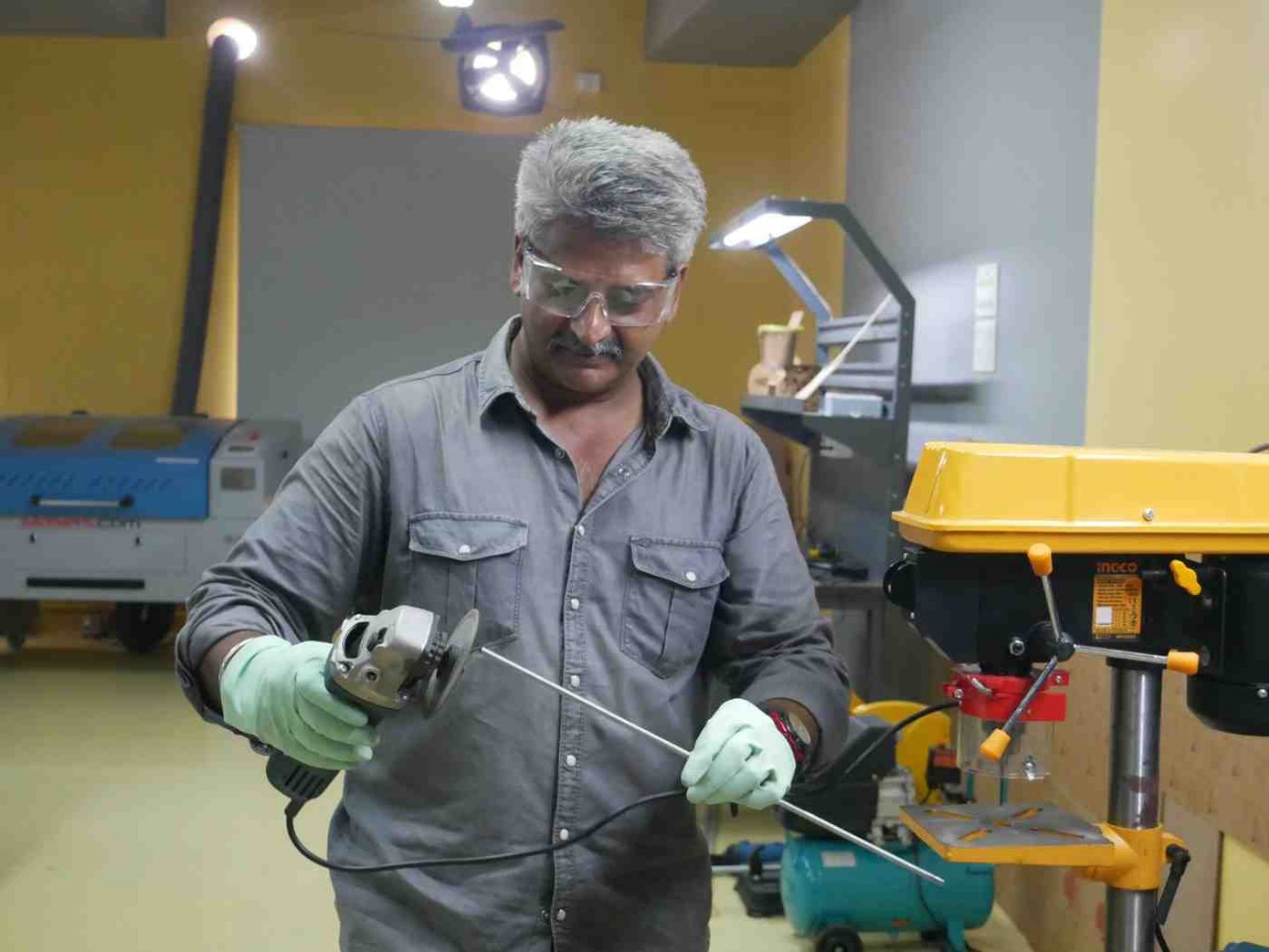
| CNC Machining of Structural Metal Parts | Aluminum extrusions, lead screws, and linear rods are cut manually and hand-finished using grinding tools. | Manual cutting can lead to inconsistent lengths, rough edges, and imprecise mating surfaces that affect alignment. |
Use a CNC 3-axis metal milling machine or cutting fixture with jigs. Ensure precise drilling, slotting, and tapping using digital fabrication. Improves parallelism, perpendicularity, and smoothness of assembly. |
| Tolerance Optimization in 3D Printed Parts | 3D printed connectors and holders are designed with tight fits. | Rods are hard to insert, causing stress or deformation during assembly. |
Apply parametric offsets: - Press fit: reduce ID by 0.1–0.3 mm - Free fit: increase ID by 0.2–0.4 mm Calibrate printer; use slot-based or clamp-fit holes for easier insertion. |
| Assembly-Friendly Design Adjustments | Assembly required extra time due to trial fitting, filing, and tightening. | Slows down assembly and introduces fitment errors. |
Add chamfers/lead-ins in slots and holes. Label parts or use alignment markers in CAD. Design brackets with small tolerance ranges to compensate for variability. |
| Design for Disassembly and Maintenance | Accessing internal parts like rod ends or couplers is difficult post-assembly. | Time-consuming maintenance; risk of damage during disassembly. |
Design modular subassemblies with tool-free fasteners (e.g., thumbscrews). Use hinged/slotted enclosures for quick access without full teardown. |
With My sucess team