Group Assignment Conclusion:
Our group assignment provided an understanding of the communication protocols available for embedded systems and their advantages, limitations, and applications. Through testing and comparing different communication methods, we gained practical knowledge of how devices exchange data in a networked environment.
Building on this knowledge, I completed the individual assignment by implementing communication between embedded devices and successfully transmitting data through a networking protocol. This group assignment helped me understand device addressing, data transmission, and troubleshooting communication issues. I gained hands-on experience in programming and testing networked embedded systems, which improved my understanding of how multiple devices can work together as a distributed system. The skills learned in this week will be valuable for developing connected devices and integrating communication features into my Future projects.
Individual Assignment:
design, build and connect wired or wireless node(s) with network or bus addresses and a local input and /or output devices
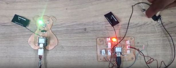
Hero Shot
What is Networking and Communication?
Networking
Networking is the process of connecting multiple devices (or nodes) together so they can share data and resources. In embedded systems, this means connecting microcontrollers, sensors, actuators, or machines to talk to each other.
Example: Connecting 10 sensors and motors on a factory floor using RS485 or Wi-Fi.
Communication
Communication is the method or process by which data is transferred between two or more devices.
It involves:
- Sender (who sends data)
- Receiver (who receives it)
- Medium (wired/wireless channel)
- Protocol (rules for data exchange)
Example: Sending a temperature reading from a sensor node to a control panel using Modbus.
Why is it Important in Embedded Systems?
In embedded systems:
- Devices are usually "smart" but need to work together
- Inputs from one device can trigger actions in another
- Communication is needed for monitoring, control, data logging, and automation
Wired Communication Method
| Communication Method | Type | Description |
|---|---|---|
| UART (Serial) | Wired | Simple, asynchronous serial communication; typically used for point-to-point data transfer. |
| I2C | Wired | 2-wire synchronous communication (SDA, SCL); allows multiple masters and slaves on the same bus. |
| SPI | Wired | High-speed synchronous communication with separate lines for data and control (MISO, MOSI, SCLK, SS). |
| CAN | Wired | Robust multi-master communication bus commonly used in automotive and industrial networks. |
| Ethernet | Wired | Standard networking technology for high-speed data communication over LAN using twisted pair or fiber cables. |
Wireless Communication methods
| Communication Method | Type | Description |
|---|---|---|
| Wi-Fi | Wireless | Long-range wireless communication standard (IEEE 802.11) used for internet and local network access. |
| Bluetooth | Wireless | Short-range wireless communication ideal for personal devices, low power, and low data rates (IEEE 802.15.1). |
| Zigbee | Wireless | Low-power mesh network protocol for IoT and sensor networks (IEEE 802.15.4). |
| LoRa | Wireless | Long-range, low-power wireless communication used in remote IoT applications (LPWAN). |
| NFC | Wireless | Very short-range communication used for contactless payment and authentication (13.56 MHz). |
| Infrared (IR) | Wireless | Line-of-sight communication used in remote controls and low-speed data links. |
ESP32’s built-in Wi-Fi
The ESP32’s built-in Wi-Fi functionality enables seamless integration into wireless networks. It can operate in multiple modes—as a client (station mode), a server, or even as an access point (AP mode)—allowing it to either connect to existing Wi-Fi networks or create its own hotspot for direct device communication. This flexibility makes the ESP32 a powerful platform for a wide range of applications, including IoT (Internet of Things) systems, web-based control panels, real-time sensor data logging, remote monitoring, and smart home automation. With support for standard internet protocols (like HTTP, MQTT, WebSocket), the ESP32 behaves like any other networked device, capable of hosting full-featured web servers or communicating with cloud platforms.
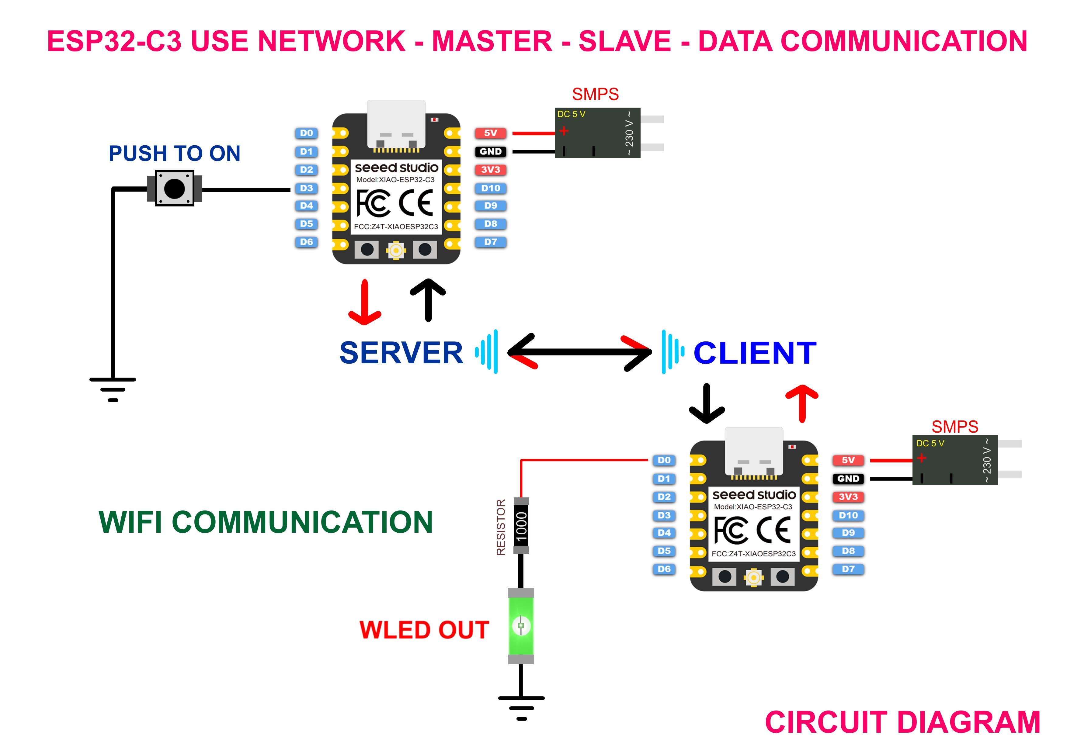
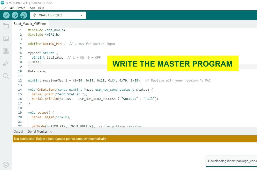
In a master-slave communication system, the master device controls the flow of data by initiating communication and managing how and when data is exchanged with one or more slave devices. In this setup, the ESP32-C3 acts as the master, while a single slave device is used for demonstration and data exchange. The master sends commands or data requests, and the slave responds with the appropriate data or acknowledgment, typically using a predefined communication protocol such as I2C, SPI, UART, or Modbus. This structured approach ensures deterministic and synchronized communication, making it ideal for applications where centralized control and coordination are required. The master-slave model is widely employed in embedded systems, industrial automation, robotics, and network infrastructure where predictable, hierarchical communication is essential.
Step by Step Demonstration:
In Arduino sketch is a program written using the Arduino programming language (based on C/C++) and uploaded to an Arduino board to control its behavior. Each sketch typically contains two main functions: setup(), which runs once at the beginning to initialize settings, and loop(), which continuously executes instructions for ongoing tasks. Sketches can control sensors, motors, LEDs, displays, and communicate with other devices using various protocols. The Arduino IDE provides a user-friendly platform to write, compile, and upload sketches via USB. Sketches are central to creating interactive, embedded, and IoT applications using Arduino-compatible boards like the UNO, Nano, or ESP32.
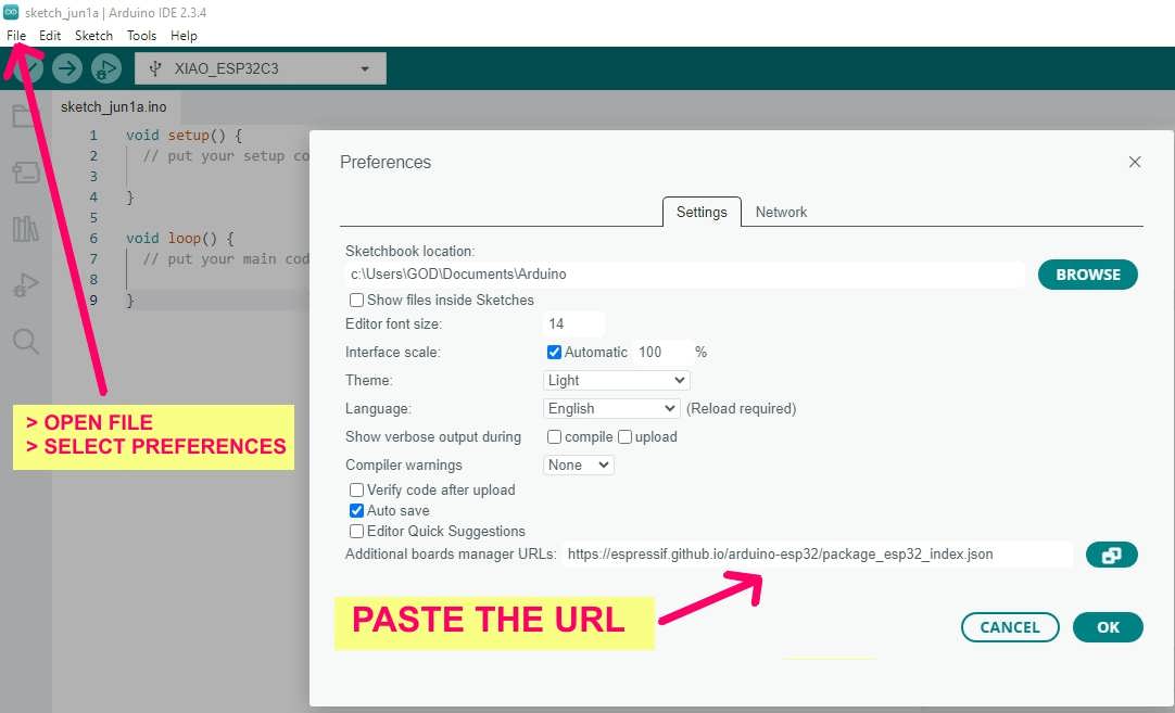
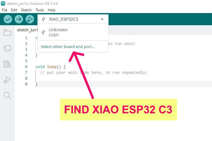
To use the ESP32 with the Arduino IDE, first open the IDE and go to File > Preferences. In the “Additional Board Manager URLs” field, add this URL: https://raw.githubusercontent.com/espressif/arduino-esp32/gh-pages/package_esp32_index.json
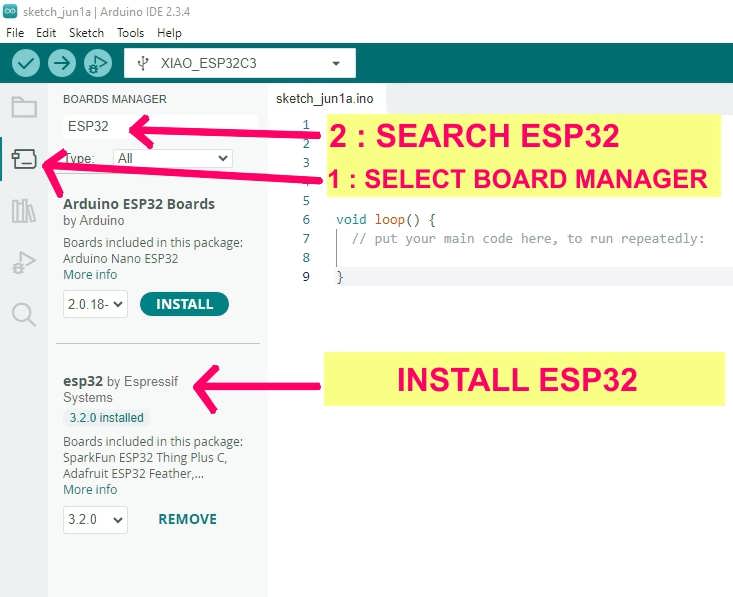
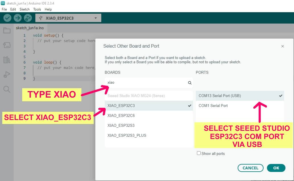
Next, go to Tools > Board > Boards Manager, search for "Seeed ESP32" or "XIAO ESP32-C3," and install the Seeed ESP32 Boards package. After installation, go to Tools > Board and select Seeed XIAO ESP32-C3. Connect the board via USB, select the correct port from Tools > Port, and you're ready to upload sketches and start development.
Next, go to Tools > Board > Boards Manager, search for
"Seeed ESP32" or "XIAO ESP32-C3", and install the
Seeed ESP32 Boards package.
After installation, go to Tools > Board and select
Seeed XIAO ESP32-C3.
Connect the board via USB, select the correct port from
Tools > Port, and you're ready to upload sketches and start development.
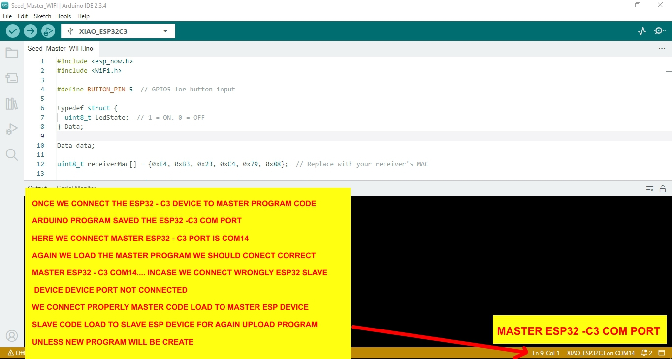
Write the Master program
verify the program
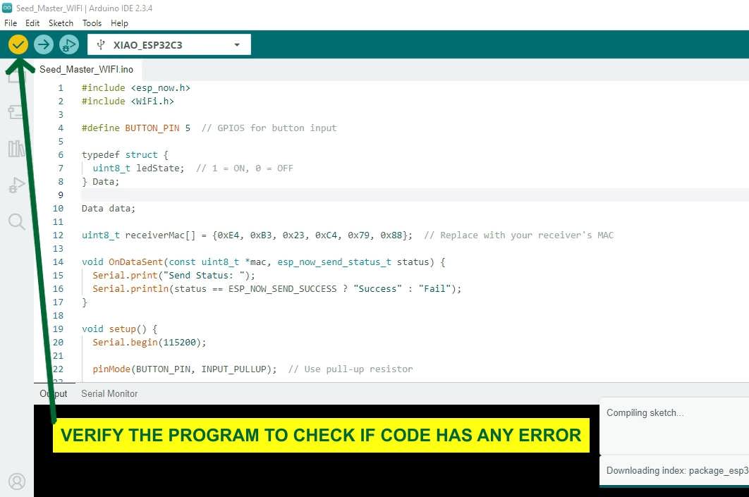
verifyied-No error in code
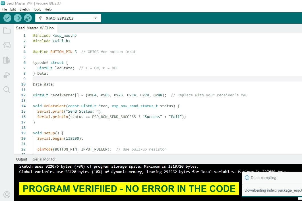
Program loaded in code
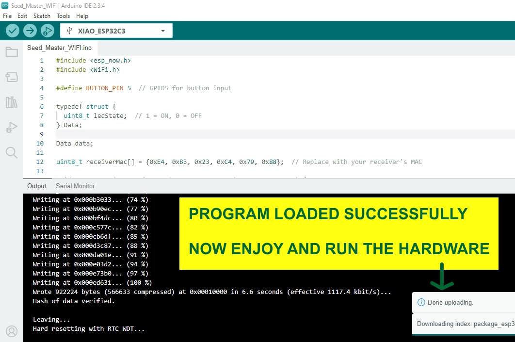
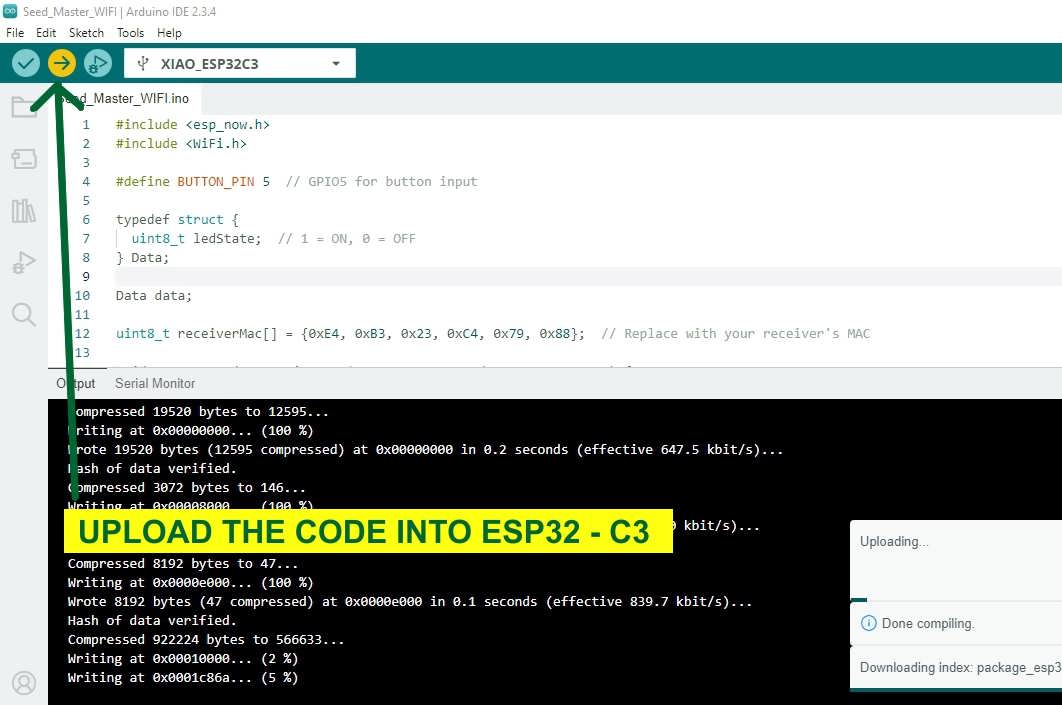
Upload Code to XIAO ESP32-C3:
- Connect your XIAO ESP32-C3 to your PC using a USB-C data cable.
- Open the Arduino IDE.
- Go to:
- Tools > Board > Seeed ESP32 Boards
➜ Select "Seeed XIAO ESP32-C3" - Tools > Port
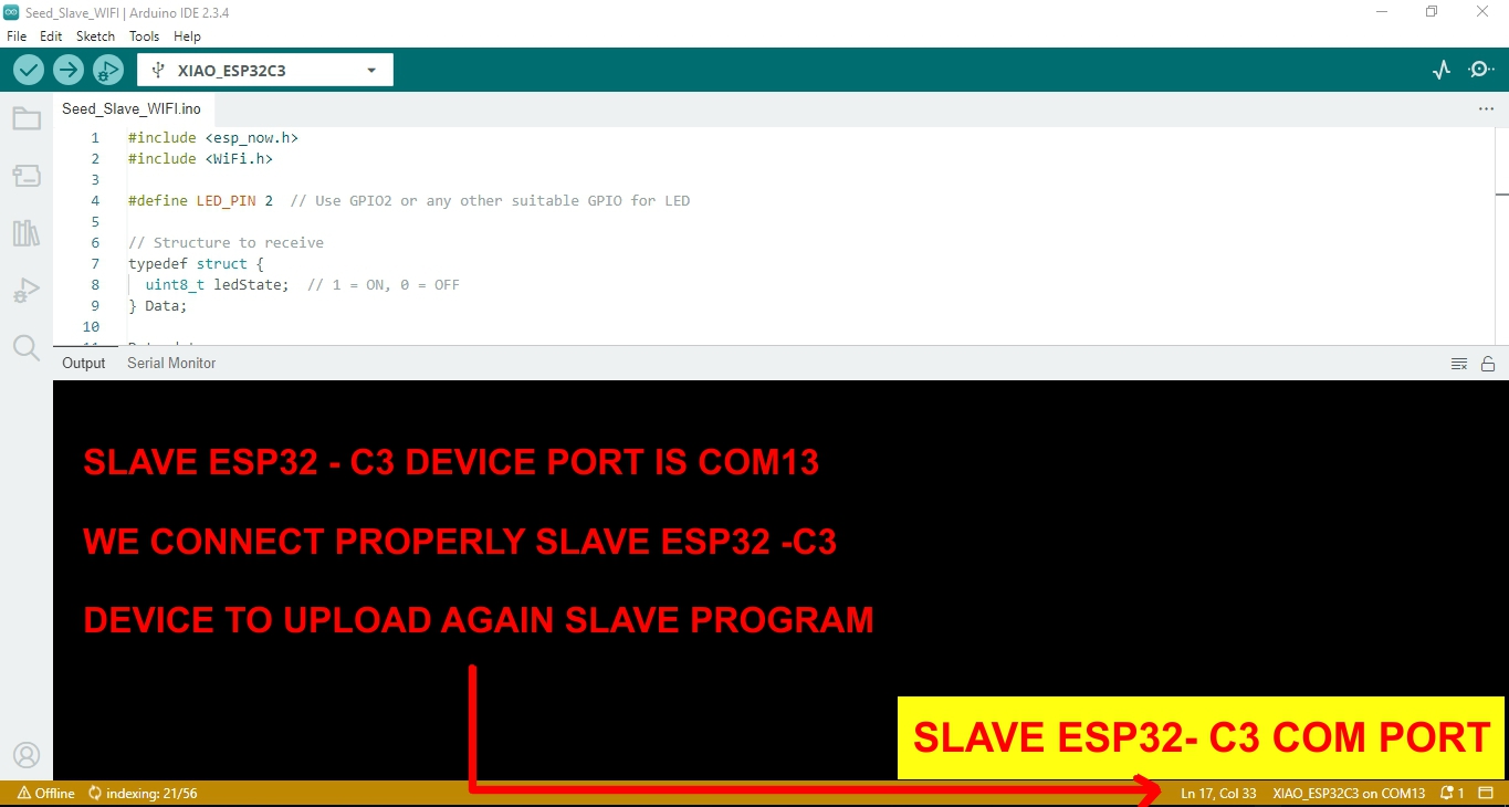
➜ Select the correct COM port (e.g., COM13 (XIAO ESP32-C3))
- Tools > Board > Seeed ESP32 Boards
- Paste or write your sketch in the Arduino IDE.
- Click the Upload (→) button in the top-left of the IDE.
- Wait for the “Done uploading” message in the console.
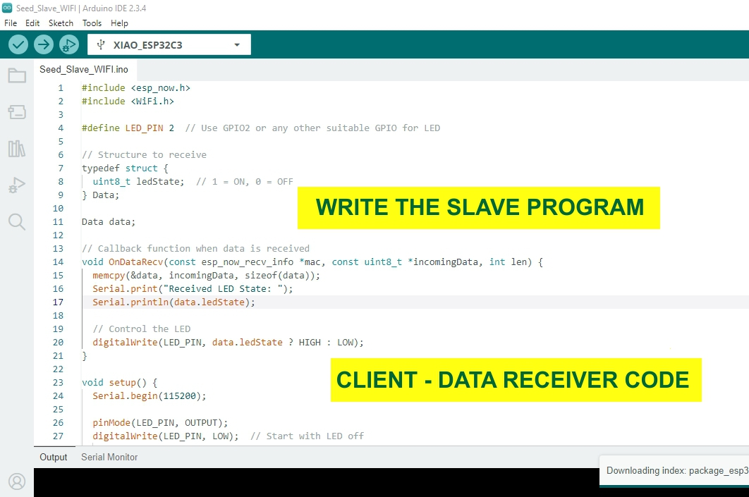
In a master-slave setup using I2C, the slave device sketch configures the microcontroller (e.g., an Arduino) to respond to data requests from the master. It uses Wire. begin(address) to set its I2C address and Wire.onRequest() to define the data to send when the master calls. The client (master) data receiver, such as an ESP32-C3, initiates communication using Wire.requestFrom() to fetch data from the slave. It reads incoming bytes with Wire.read() and processes or displays them, such as printing to the Serial Monitor. This setup enables reliable, request-based communication between devices in embedded systems and sensor networks
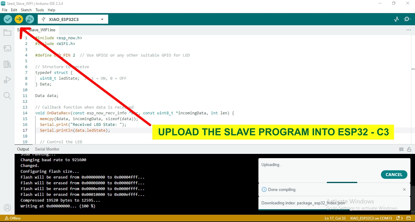
To upload the slave program to an ESP32 (as an I2C slave) using the Arduino IDE, first connect your ESP32 to your PC via USB. Open the Arduino IDE, go to Tools > Board, and select your ESP32 model (e.g., Seeed XIAO ESP32-C3). Also, select the correct COM port under Tools > Port. Write the I2C slave sketch using Wire.begin (address) and Wire.onRequest() to send data. Click the Upload button (→). Wait for the “Done uploading” message. Your ESP32 is now configured as a slave device, ready to respond to a master’s data requests using I2C protoco
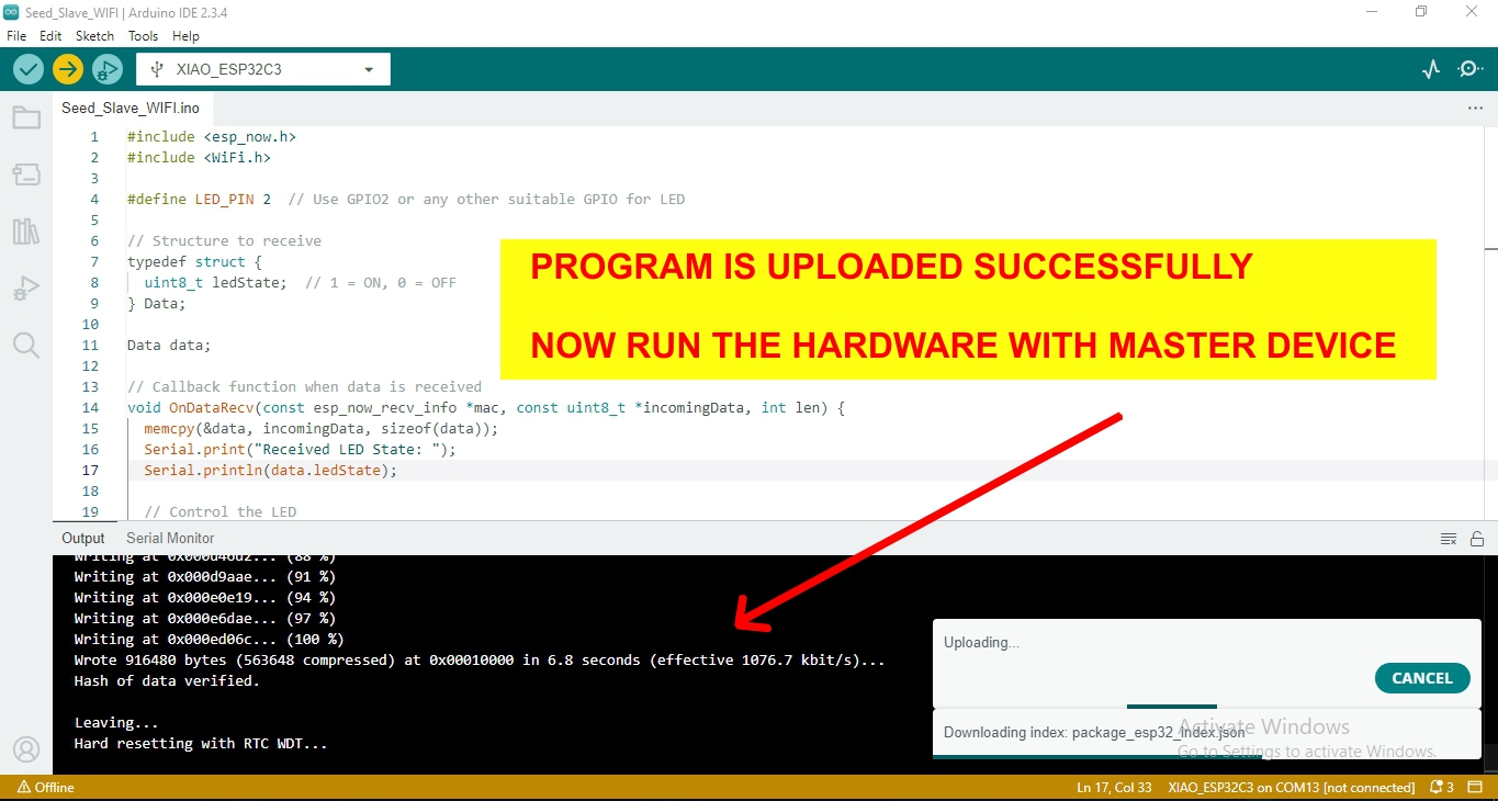
After successfully uploading the slave program to the ESP32, you can run the hardware by connecting it to a master device, such as another ESP32. For I2C communication, connect SDA to SDA, SCL to SCL, and GND to GND between both boards. Upload the master sketch to the second ESP32, which sends a request to the slave (address 0x08) and receives a response. The slave sends data using Wire.write(), while the master reads it with Wire.requestFrom() and Wire.read(). When powered on, the master receives and displays the slave’s response, confirming successful communication between both ESP32 boards.
Problem I Encountered During My Embedded Networking and Communications Assignment
I attempted to establish communication between two ESP32-C3 boards using the ESP-NOW protocol. Although ESP-NOW is a powerful peer-to-peer protocol with low latency and no need for Wi-Fi, I faced several issues during setup and testing.
Problem: Device Pairing and Message Failure
Issue:
Initially, the sender device was not able to transmit messages to the receiver. The devices were powered and programmed correctly, but no data was being received on the other end.
Diagnosis:
- I checked the MAC address format and found that it was incorrectly typed.
- I also realized I hadn’t added the peer device properly using
esp_now_add_peer().
Solution:
- I retrieved the correct MAC address of the receiver using a serial print function and updated the sender code.
- I added the peer registration code with correct parameters (MAC address, encryption disabled, and communication channel).
- I also added debug print statements to ensure the data was being sent and callbacks were triggering as expected.
Once corrected, communication was successfully established, and the receiver started receiving the expected data from the sender.