Mechanical Design & Machine Design
Home ← →
Objective of this Week
Mechanical Design
- Design a machine that includes mechanism + actuation + automation + application
- Build the mechanical parts and operate it manually
Machine Design
- Actuate and automate our machine
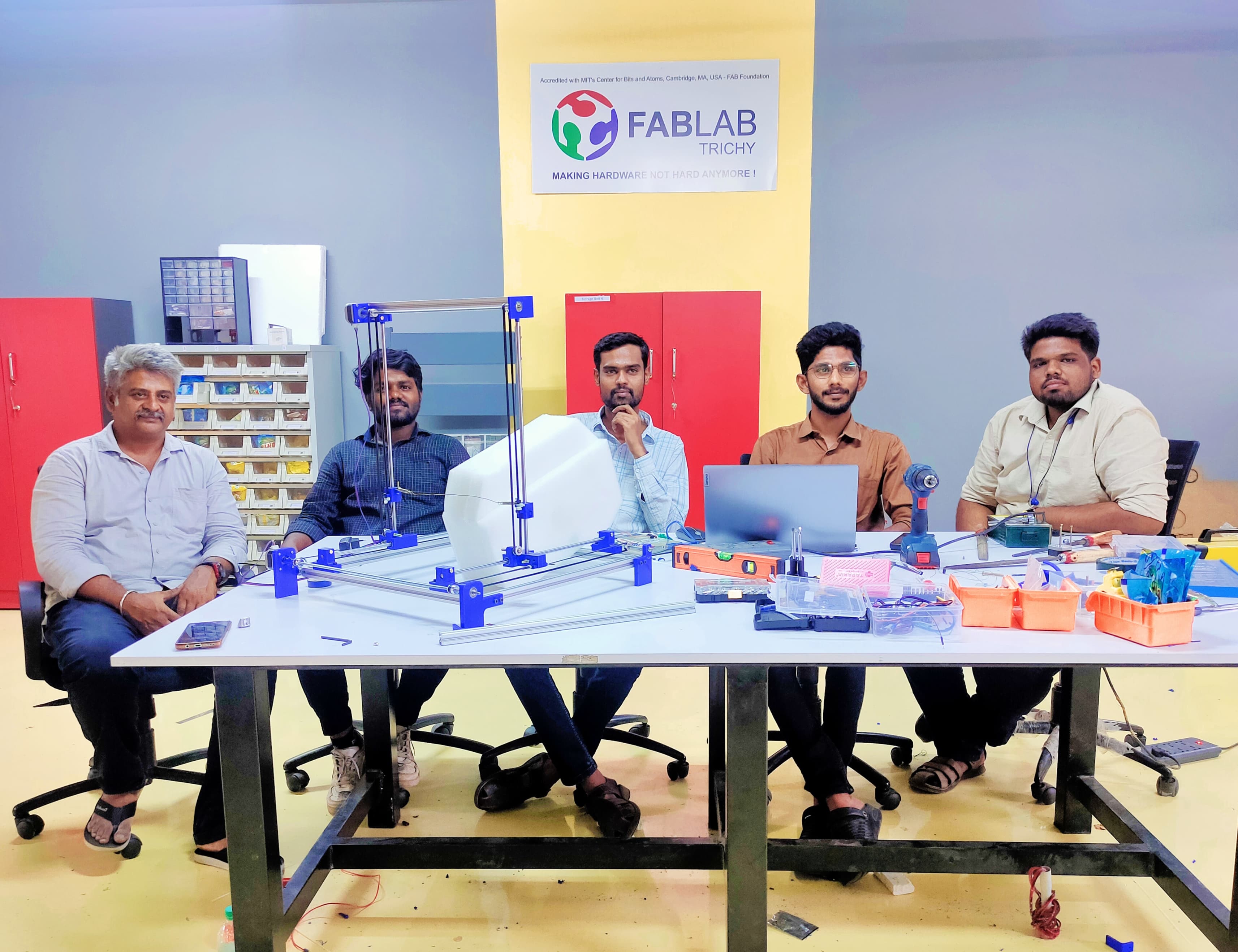
Hero shot
Presentation
Problem Identification
In our lab we have the thermal cutting machine, but it has some issues by using that.
- Safety Issues - Students in our lab they are using it manually so it seems like it may be affect their hands in case of any accidence.
- Finishing - Students can’t be done their design according to their designs properly.
- Readiness - Students can’t attain their working model more frequently within their restricted time.
Idea Generation
So we decided to build a machine which can be accurate and precise. The initial idea was to develop a lever handled the mechanism and then the mechanical movements makes some mistakes and then we thought on work on the Automated the X and Y axis machine movements by using the stepper motors and Universal G-code software, the machine movements can be done with add some limit switches to restrict the boundaries.
Foam Cuttting Machine
For the Machining week we dicussed a lot of things, we are parellely did the secondary research to do what we build the machine week. At the time we found out the Foam cutting machine in online, we all are really interested to build that, and our wish also to do build the machine for the uses of students in their fast prototyping in their ideas.
A Hot Wire Foam Cutter is a simple yet effective machine that uses a resistive wire heated by electricity to cut through foam like EPS or XPS.
| Features | EPS (Expanded Polystyrene) | XPS (Extruded Polystyrene) |
|---|---|---|
| Structure | Made of small beads fused together | Continuous closed-cell structure |
| Appearance | Looks grainy with visible beads | Smooth and dense surface |
| Density | Lower (10–30 kg/m³) | Higher (28–45 kg/m³) |
| Thermal Insulation | Good, but less than XPS | Excellent thermal insulation |
| Water Absorption | Absorbs more water over time | Very low water absorption |
| Strength | Less compressive strength | Higher compressive strength |
| Cost | Cheaper | More expensive |
| Eco-friendliness | More recyclable | Less recyclable |
Roles and Responsibilities
| Persons | Key Roles | |
| Manikandan R | Design the machine Documentation our work | |
| Gayathri Prasad | Components Procurement Machine Assembly | |
| Uthaya Velraj | Electronics hardware Fabrication | |
| Muhesh Kumar | Software |
Progress Start
After we done our exploration we found out the Hot wire Foam cutting machine tutorial, by refering it we get some ideas how to create it for our assignment.
We take that machine design as our refernce to build the machine from scratch.
Machine Design
For designing the machine Manikandan take the priority to complete that.
By using the Fusion 360 Software he start the machine design from scratch.
Fusion 360
We used aluminum extrusion profiles as the machine's base for strength and precision.

As per our requirement he created six parts of Aluminium profile, four for the base, one as the workpiece holder, and one for the motor holder at the top.
Then by using the assembly option he assemble it, and Futher take the required components from the MCmaster


For the connectors and holders parts he designed it, and will take out the parts completely from the 3D printing.


For the detailed designing work you can go and check Manikandan page.
Rendering

Procurement
As per the machine design Gayathri Prasad going to purchase the requied Mechanical and Electronics parts by assissting Manikandan and Uthaya.
Bill of Materials
Mechanical Components
| Components | Spcification | Quantity | Reference Link |
|---|---|---|---|
| 20x20mm T-slot aluminum profiles | 20x20mm, 12 feet length | 1 | Link |
| Linear Rails Rods | 10mm Linear Rails Rods, 500mm length | 4 | Link |
| Corner Brackets | T-slot profile corner brackets | 6 | Link |
| Nuts | M5 nuts for T-slot Profiles | 50 | Link |
| Linear bearings | Linear bearings 10mm | 6 | Link |
| GT2 Belt | 5M GT2 Timing Belt 6mm Width | 1 | Link |
| Tooth Pulley | 20 Teeth 5mm Bore Belt Pulley Wheel | 4 | Link |
| Idler Pulley | 4 | Link | |
| Bearing | Bearing 5x16x5mm | 2 | Link |
| Spring | 2 | Link | |
| Hot wire | 1 | Link | |
| Foam Material | 1 | Link |
Electronics Components
| Components | Spcification | Quantity | Reference Link |
|---|---|---|---|
| Stepper Motor – NEMA 17 | 3 | Link | |
| Arduino Mega | Mega 2560 ATmega2560-16U2 Board without USB Cable for Arduino | 1 | Link |
| DC-DC Converter | 1 | Link | |
| Limit Switch | Mini Endstop Limit Switch with 1M Cable | 6 | Link |
| DC Power Supply | SMPS Mean Well LRS-150-12 – 12V 12.5A – 150W SMPS | 1 | Link |
| Stepper motor driver | TB6600 | 3 | Link |
3D Printing
Flash Print
After completed the Machine design Manikandan 3D printed the design parts. In our lab we have the Flash Forge 3D printer so he uses the Flash print software for slicing the 3D model.
He export the required 3D printed parts from Fusion 360 as STEP File. Then import it into the slicing software.
He did the supports and for slicing he gave the infill density - 15%, infill pattern - Hexagon, also enable the raft for optimizing the final good print.
If you give without raft, when the print part is more height then it will remove from the bed easily
So we must enable the raft for long time printings. Then set up the nozzle temperature upto 205 degree celcius and bed temperature upto 50 degree celcius.
Then give the slicing and take out the Gcode, it seems like the print will be finishing upto 25 hrs and 45 mins, after download the G-code and import it into the flash forge
He load the filament PLA pro blue colour according to our colour expectation as well.


Then start the 3D printer with properly check with the bed layer whether it is good or not.
Start the printing in night, so morning we came and check the print, its going well.

After the complete printing it takes the time upto 25 hrs and 27 mins and the filament usage upto 73.1 m


Fabrication and Assembly
Gayathri Prasad start the Fabrication part, Manikandan assist him to proper work ,at first we cut out the required length of all parts like aluminium profile, linear rods, etc..


Gayathri also give the smootheness to the cutting linear rods by grinding them properly

Manikandan did the grinding in the aluminium profile corners properly.

In between the aluminium profile space the burr has coverd so Gayathri removed it by using the plier tools.

Electronics
Now lets jump to this electronics, Automated Machine movements needs too much of power, that’s where we introduce our Big Boy NEMA - 17 to get done the bigger Task.
NEMA - 17 Specifications
- Shaft dimensions. Ø 5 x 22 mm (4mm flat spot)
- Connection. 4 Cables.
- Holding torque. 0.59 Nm.
- Rated voltage. 3.6 V.
- Rated current. 2.0 A.
- Step angle. 1.8 ° ±5 %
- Phase resistance. 1.8 Ω
Our Big Boy is a Drifter, he needs the proper instruction set to drift in a proper way thats where we introducing our Big Brain AS9984 Motor Driver, he chunks our boy and make him work in a proper way. He is a complete microstepping motor driver with built-in translator for easy operation. It is designed to operate bipolar stepper motors in full, half, quarter, eighth, and sixteenth-step modes.
Specifications of A4988
| Minimum operating voltage: | 8 V |
| Maximum operating voltage: | 35 V |
| Continuous current per phase: | 1 A2 |
| Maximum current per phase: | 2 A3 |
| Minimum logic voltage: | 3 V |