
STM32
Hero Shot

Summary
This week, I explored the Nucleo STM32F401 microcontroller by following a step-by-step tutorial from DigiKey’s video. My goal was to understand the STM32F401 architecture, set up the development environment, configure the board, write a simple program, and upload it using STM32CubeIDE. I successfully ran a basic LED blink test, which confirmed that the setup was working correctly.This documentation outlines the chip specifications, software installation process, project setup, programming, and key learnings from the experience.
Work Process Detail
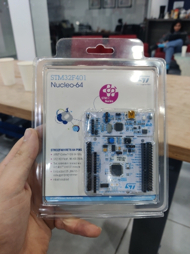
1. Understanding the STM32F401 Chip Specifications and Features
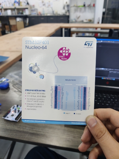
Before writing code, I started by understanding the STM32F401RE microcontroller to get an overview of its capabilities and architecture.
Key Features of the STM32F401RE (ARM Cortex-M4)
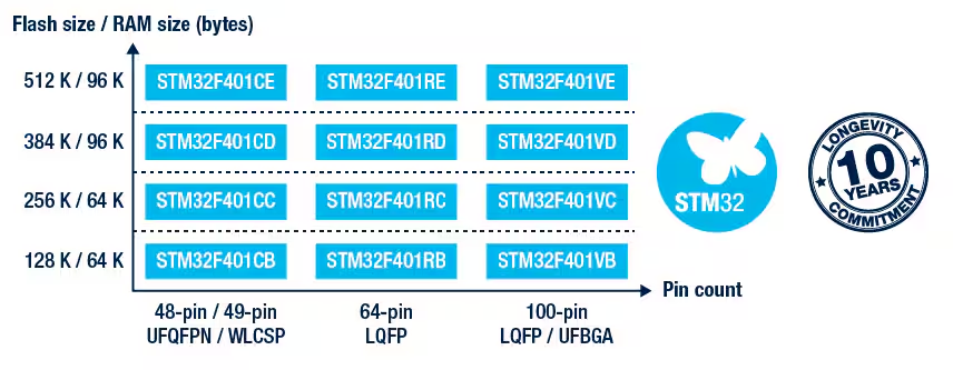
✅ Processor: ARM Cortex-M4, running at 84 MHz, optimized for performance and low power consumption.
✅ Memory: 512 KB Flash (for program storage) and 96 KB RAM.
✅ GPIO: Multiple General Purpose I/O (GPIO) pins, supporting digital I/O, ADC, PWM, and communication interfaces.
✅ Timers: Several hardware timers, which can be used for PWM, event counting, and time-based control.
✅ Interfaces: Supports I2C, SPI, UART, CAN, and USB for peripheral communication.
✅ Floating Point Unit (FPU): Enables efficient mathematical computations, useful for DSP applications.
✅ Power Efficiency: Designed for low-power applications, with multiple power-saving modes.
✅ ST-Link Debugger Integration: Built-in ST-Link/V2-1 for programming and debugging without additional hardware.
These features make the STM32F401RE a powerful choice for embedded systems, robotics, IoT, and industrial applications.
2. Setting Up the Development Environment
I started by setting up the required tools and software for programming the Nucleo STM32F401.
✅ Installed STM32CubeIDE, the official IDE for STM32 microcontrollers.
✅ Connected the Nucleo STM32F401 board via USB, ensuring it was detected by my system.
✅ Verified that the board was properly recognized and identified the correct ST-Link Debugger and COM port.
3. Creating a New Project in STM32CubeIDE
Once the environment was ready, I followed the tutorial to create a new STM32 project:
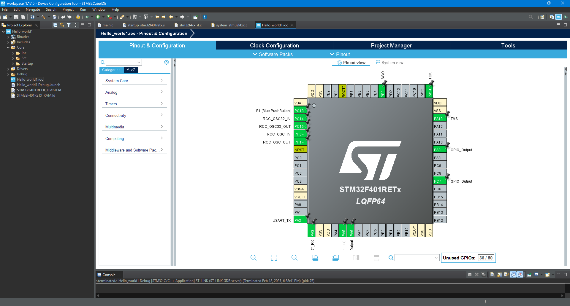
✅ Opened STM32CubeIDE and selected Nucleo-STM32F401RE as the target board.
✅ Configured GPIO settings, ensuring that PA5 (the onboard LED) was set as an output pin.
✅ Enabled system clock configuration to ensure proper timing.
✅ Saved the configuration and generated boilerplate code using STM32CubeMX.
4. Writing and Uploading the LED Blink Program
After setting up the project, I wrote a simple LED blink program to toggle the onboard LED at 1-second intervals.
C Code for Blinking an LED (STM32CubeIDE)
while (1)
  {
	  HAL_GPIO_TogglePin(GPIOA,GPIO_PIN_9);
	  HAL_Delay(750);
    /* USER CODE END WHILE */


    /* USER CODE BEGIN 3 */
  }
✅ Successfully built and compiled the project in STM32CubeIDE without errors.
✅ Flashed the program onto the STM32F401RE board using the built-in ST-Link programmer.
✅ Observed the LED blinking every second, confirming that the board was running the program correctly
Learning Outcome
This experience introduced me to STM32 development, focusing on bare-metal programming and GPIO control. I learned how to:
- Set up STM32CubeIDE and configure an STM32 project from scratch.
- Understand STM32F401RE’s architecture, including its GPIO, clock system, memory, and communication interfaces.
- Work with STM32 registers, manually enabling GPIO clocks and toggling output pins.
- Flash and debug firmware using the built-in ST-Link debugger.
- Compare STM32 development with other microcontrollers (e.g., ESP32, RP2040), understanding the advantages of ARM-based microcontrollers.
Working with the STM32F401RE has strengthened my understanding of embedded C programming, microcontroller initialization, and peripheral control. Moving forward, I plan to explore advanced features like UART, timers, and PWM to expand my embedded systems knowledge. 🚀