Week 06 - Electronics Design

Group Assignment:
• Use the test equipment in your lab to observe the operation of a microcontroller circuit board (as a minimum, you should demonstrate the use of a multimeter and oscilloscope)
• Document your work on the group work page and reflect what you learned on your individual page
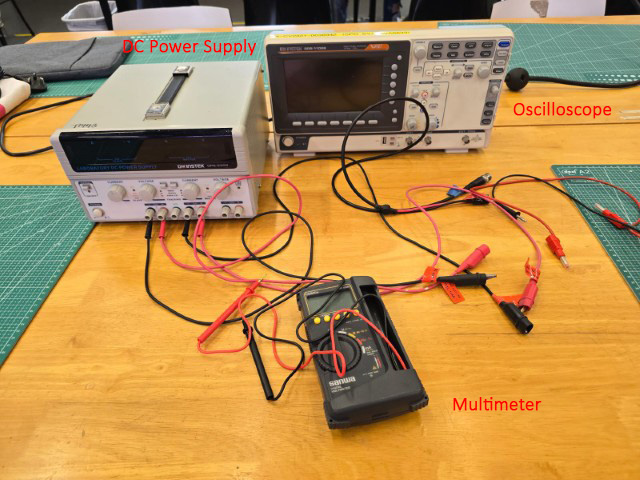
For our Group Assignment, we tested circuits using the following equipment in our Lab:
• Multimeter (Sanwa CD800a)
• Oscilloscope (GW Instek GDS-1102B)
• Bench Power Supply (GW Instek GPS – 3303)
Multimeter
A multimeter is a tool used to measure electrical properties like voltage, current, and resistance. We used the multimeter on the following electronic components shown in the image below.
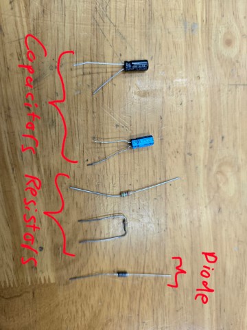
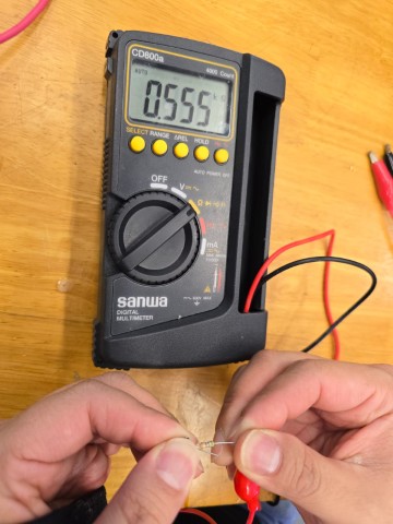
A resistor is an electronic component that limits or controls the flow of electrical current in a circuit. For the resistor, we measured the resistance to be 0.55kΩ (Around 500Ω)
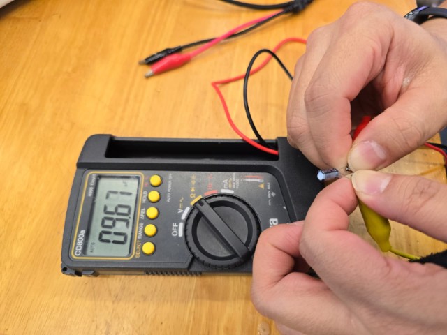
A capacitor is an electronic component that stores and releases electrical energy. The unit of measurement is usually microfarads (µF), and we measure this to be 9.67 µF.
A diode is an electronic component that allows electricity to flow in only one direction, like a one-way valve for electricity. We tested if our diode is working by first applying the multimeter probes to the diode in one direction and then applying the probes in the opposite direction. Our results show that the diode is working (current only flows in one direction).A diode is an electronic component that allows electricity to flow in only one direction, like a one-way valve for electricity. We tested if our diode is working by first applying the multimeter probes to the diode in one direction and then applying the probes in the opposite direction. Our results show that the diode is working (current only flows in one direction).
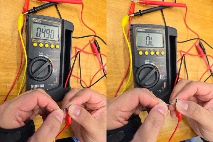
A multimeter can also be used to check the continuity of a circuit as demonstrated in the video below. The multimeter beeps when there is continuity detected in the circuit between two points.
It can also be used to measure a voltage across two points of a live circuit, such as shown in the video below where we are measuring the voltage across a blinking LED light. You can see in this example that the Voltage measurement increases as the LED blinks on.
Oscilloscope
We learnt that the multimeter measures electrical properties at only one point in time. To observe electrical properties over time, we will need to use an oscilloscope.
Setup
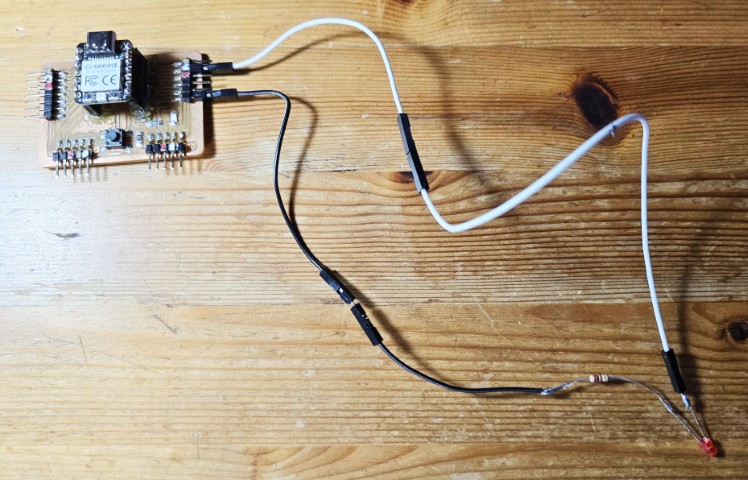
For our test, we use a development board with a Seeed Studio RP2040 that produces a signal to light up a blinking LED. We use the oscilloscope to capture and observe the waveform.
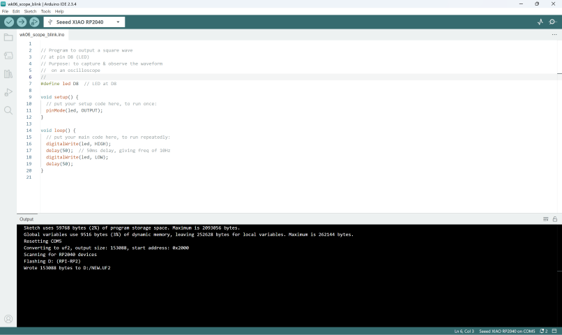
Below is the code from our Instructor Steven Chew, that we used for this experiment.
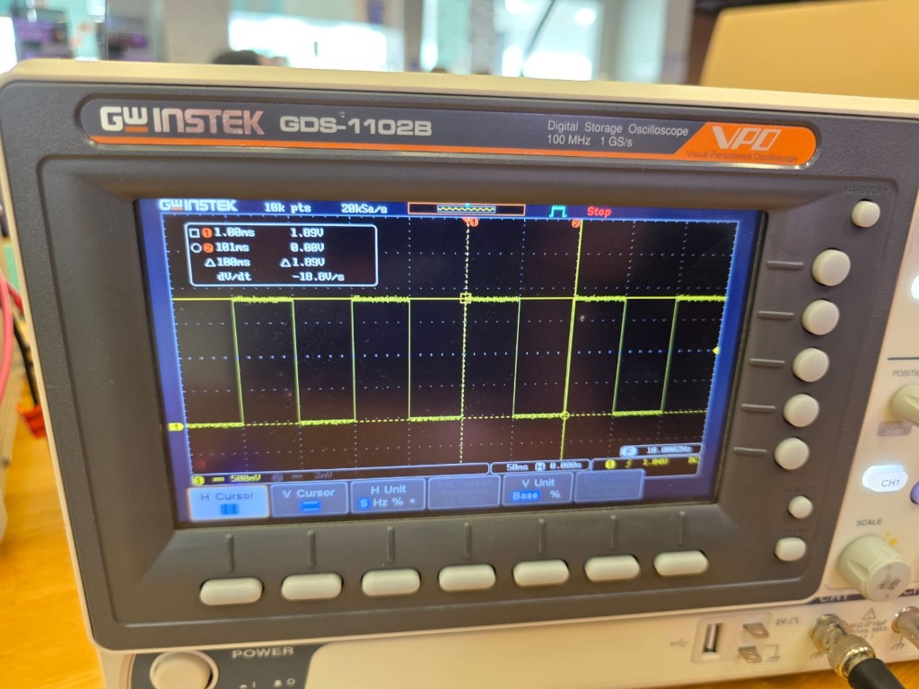
Oscilloscope operation
Here is how we operated the oscilloscope:
1. Switch on the oscilloscope. It takes a few seconds to initialize.
2. Connect the probe to the circuit. We connected the probe tip to the test point we wanted to analyse (we did this at each end of the LED using the crocodile clips on the probe
3. Press AUTOSET
4. Adjust the oscilloscope settings by tuning the VARIABLE nob to frame the wavelength to analyze
5. Press STOP to stop the wavelength for analysis
6. Use the CURSOR button to set the section of the signal that you want to analyze
7. The oscilloscope’s tools automatically provide the frequency (on x-axis) and voltage (on y-axis)
8. We compared it against the expected values from our circuit’s design.
| Expectation | Oscilloscope |
|---|---|
| Square wave for digital output | Observation is consistent with expectation |
| The signal’s frequency to be 10Hz | Observation is consistent with expectation |
| The voltage across the LED to be 0.951V (We measured this with the multimeter) | Observation is consistent with expectation. Our recorded reading was 0.945V (1.89V divided by 2). |
Below is a video of the oscilloscope operation process.
Bench Power Supply
A bench power supply is a device that provides a controlled and adjustable source of electrical power for testing and powering circuits. We used it to power our RP2040 blinking light circuit, which was previously connected via USB in the previous test.
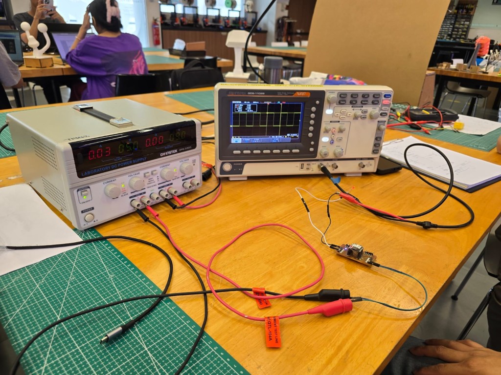
Here is what we learnt about the Bench Power Supply:
Controls
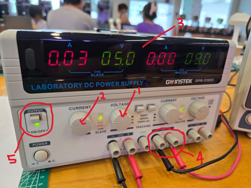
1. Voltage Adjustment Knob/Dial – Sets the output voltage.
2. Current Limit Knob/Dial – Sets the maximum current allowed before limiting kicks in.
3. Display Screen – Shows real-time voltage and current output.
4. Output Terminals – Usually red (+) for positive and black (-) for ground.
5. Output Button – This feature allows us to connect our circuit to the power supply unit and only output when the button is pressed.
How to Use a Bench Power Supply
1. Turn it on and set the voltage to match the circuit’s needs. In our case, this was 5V.
2. Set the current limit slightly above your circuit’s expected current draw. I suppose this feature is useful if you already know how much current your circuit should draw. We did not know this, but it turns out that our current draw was 300mA. Since it is a current limit (and not the actual output current value), any value we set will work as long as it is above 300mA.
3. Connect the leads to your circuit (red = positive, black = ground).
4. Power on the output and observe the circuit's behavior.
5. Check the current reading to ensure everything is working correctly. As mentioned in point 2 in this section, our current reading was 300mA. We had set the current limit to something higher, but when the output button is pressed and the circuit is powered on, we can see the current reading drop from the value we had set to the 300mA value.
Safety Tips
• Always set the correct voltage before connecting to your circuit.
• Use current limiting to prevent burning out components.
• Double-check polarity before connecting to avoid damage.
Conclusion
We learnt how to use 3 different types of electronics testing equipment for this Group Assignment. From the eyes of absolute beginners like us, these tools look very complicated and intimidating with lots of readings, buttons, symbols and settings, they eventually make more sense when we tried using them and learnt more about their purpose and functions.
We encourage anyone who wants to learn more about these tools to just try doing simple things with them. Here are some things we learnt from the Group Assignment:
• A multimeter measures electrical properties at only one point in time, while an oscilloscope is used to observe electrical properties over time
• The current reading on the bench power supply’s display is first set as a current limit, before displaying the true current reading (below the current limit value) when the output button is pressed
• On an oscilloscope, digital signals are represented by a square wave, while analog signals look like a sine wave.
• Polarized capacitors can pop when you reverse the direction of the current flowing through them
• Always practice proper safety while working with electricity. Don’t be this guy (ElectroBOOM).
Additional Links: Beginner-friendly Guides
Being new to electronics, we went through some explainers/guides to get us started. Here are some YouTubes we recommend:
• How to use a multimeter like a pro, the ultimate guide by James Gatlin
• How to use a DC Power Supply | Basic Electronics by Engineer Joules
• Oscilloscope Tutorial (Basics 101) by TheGeekPub
You can watch these tutorials before or after doing your Group Assignment. We did it after our Group Assignment, and it helped us to better understand some of the equipment that we tested.
