LEDs (Light Emitting Diodes) are becoming increasingly popular among a wide range of people. When a voltage is given to a PN Junction Diode, electrons, and holes recombine in the PN Junction and release energy in the form of light (Photons). An LED’s electrical sign is comparable to that of a PN Junction Diode. When free electrons in the conduction band recombine with holes in the valence band in forward bias, energy is released in the form of light.
setup() and loop() are two fundamental Arduino functions for controlling the behavior of your board. The Arduino framework automatically calls these functions, which form the foundation of any Arduino program.
The setup() function is only called once when the Arduino board boots up or is reset. Its goal is to set pin modes, initialize variables, and execute any other necessary setup tasks before the main loop begins. This function can be used to configure settings that should only be changed once over the board’s lifespan.
The loop() function is the heart of an Arduino program. After the setup() function is executed, the loop() function starts running repeatedly until the Arduino is powered off or reset. It contains the main code that performs the desired tasks, controls the board, user input. Whatever is included in the loop() function will be executed in a continuous loop, allowing the Arduino to perform its intended functions continuously.
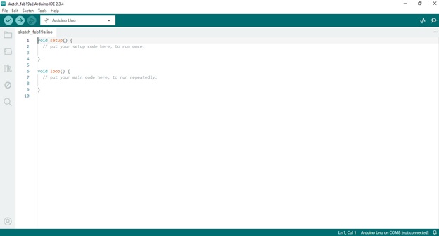
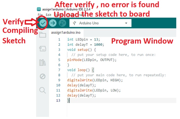
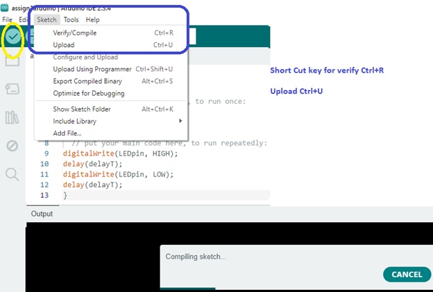
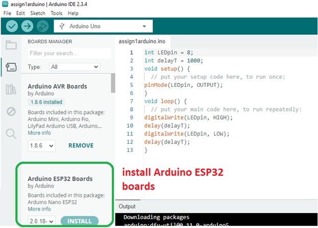
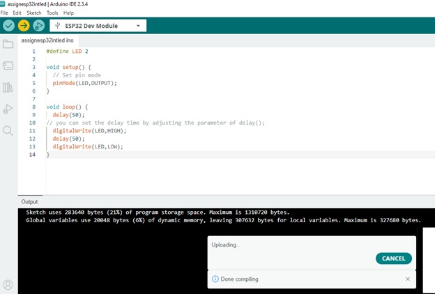
Arduino Sketch Window
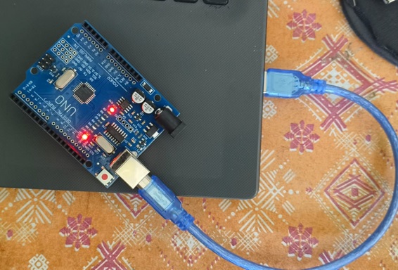
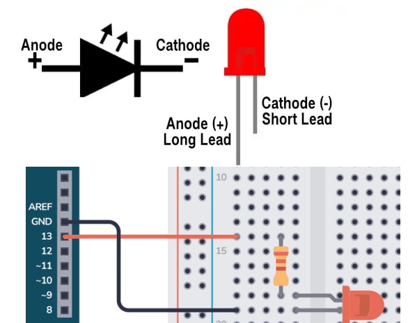
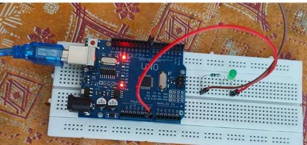
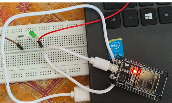
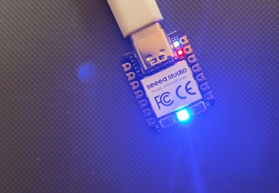
Hardware Setup Diagram
LED blinking Program
int LEDpin = 13;
//Declare an integer variable 'LEDpin' and set it to 13, which represents the pin number connected to the LED.
int delayT = 1000;
//Declare an integer variable 'delayT' and set it to 1000, which represents the delay time in milliseconds (1 second).
void setup() {
//The setup function runs once when the microcontroller is powered on or reset.
pinMode(LEDpin, OUTPUT);
// Set the pin mode of 'LEDpin' (pin 13) to OUTPUT, indicating that it will be used to send signals to the LED.
}
void loop() {
//The loop function runs continuously after the setup function, creating an infinite loop.
digitalWrite(LEDpin, HIGH);
// Set the digital output of pin 13 to HIGH (turn the LED on).
delay(delayT);
//Wait for the duration specified in 'delayT' (1000 milliseconds or 1 second).
digitalWrite(LEDpin, LOW);
// Set the digital output of pin 13 to LOW (turn the LED off).
delay(delayT);
// Wait for the duration specified in 'delayT' (1000 milliseconds or 1 second) before repeating the loop.
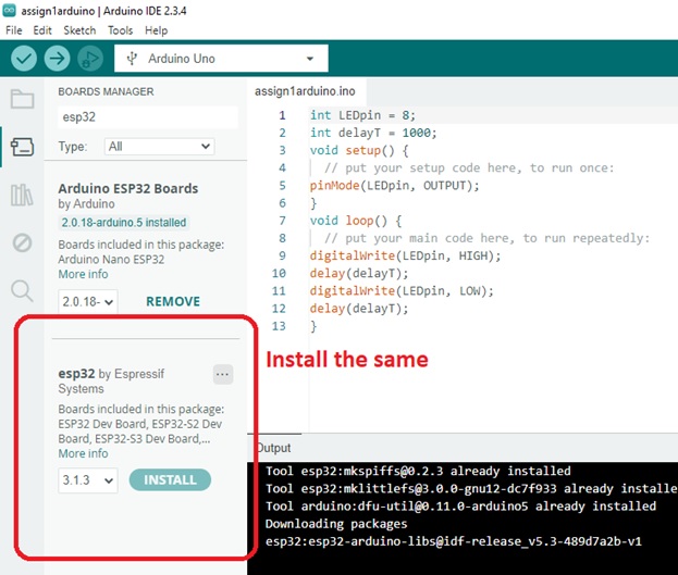
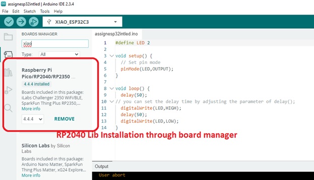
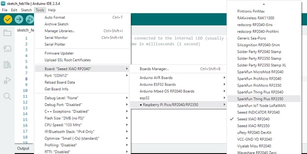
I am unable to perform the operations
So I followed the steps in below link
https://randomnerdtutorials.com/installing-the-esp32-board-in-arduino-ide-windows-instructions/
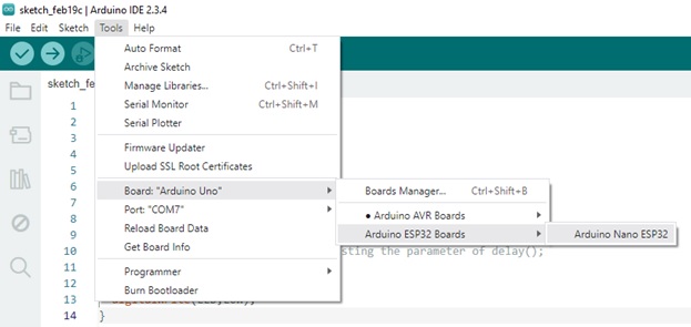
#define LED 2
void setup() {
// Set pin mode
pinMode(LED,OUTPUT);
}
void loop() {
delay(50);
// you can set the delay time by adjusting the parameter of delay();
digitalWrite(LED,HIGH);
delay(50);
digitalWrite(LED,LOW);
}
After Installing this driver in my windows I am unable to communicate to ESP Dev32 module

Program is transferred over COM10 Port to ESP Dev32 Module
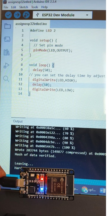
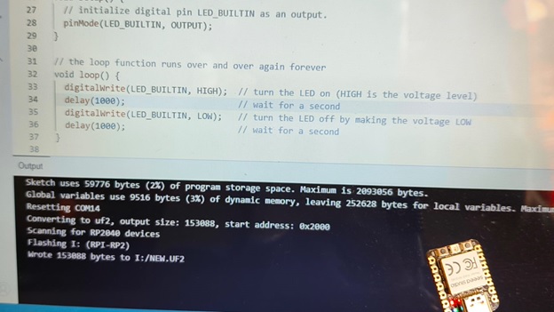
Writing the code through Arduino IDE
// the setup function runs once when you press reset or power the board
void setup() {
// initialize digital pin LED_BUILTIN as an output.
pinMode(LED_BUILTIN, OUTPUT);
}
// the loop function runs over and over again forever
void loop() {
digitalWrite(LED_BUILTIN, HIGH); // turn the LED on (HIGH is the voltage level)
delay(1000); // wait for a second
digitalWrite(LED_BUILTIN, LOW); // turn the LED off by making the voltage LOW
delay(1000); // wait for a second
}