Design is all around us, shaping everything from the apps we use to the buildings we live in. Whether it's a simple sketch or a complex 3D model, design plays a crucial role in how we interact with the world. In this introduction, we’ll explore the basics of 2D and 3D design, their differences, and how they are used in various industries.
What is 2D Design?
2D design refers to artwork or visual content created on a flat surface. It includes drawings, graphics, and digital designs that exist in only two dimensions—height and width. Examples include:
Graphic design (logos, posters, website layouts)
Illustrations (digital or hand-drawn)
Blueprints and technical drawings
In 2D design, elements like color, line, shape, and texture are used to create depth and visual impact, even though there is no physical depth.
What is 3D Design?
3D design adds an extra dimension—depth—to visual creations, making them appear more realistic and tangible. This is commonly seen in:
Architecture (building models and floor plans)
Product design (creating prototypes)
Animation and gaming (3D characters and environments)
3D design allows for better visualization of objects before they are physically created, making it an essential tool in industries like manufacturing, film, and virtual reality.
2D-Raster : GIMP
GIMP is a multi-platform tool to create and edit images of all kinds. GIMP is an acronym for GNU Image Manipulation Program.
Steps:
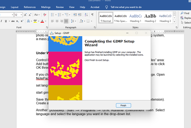
Launch GIMP: Open the GIMP application on your computer.
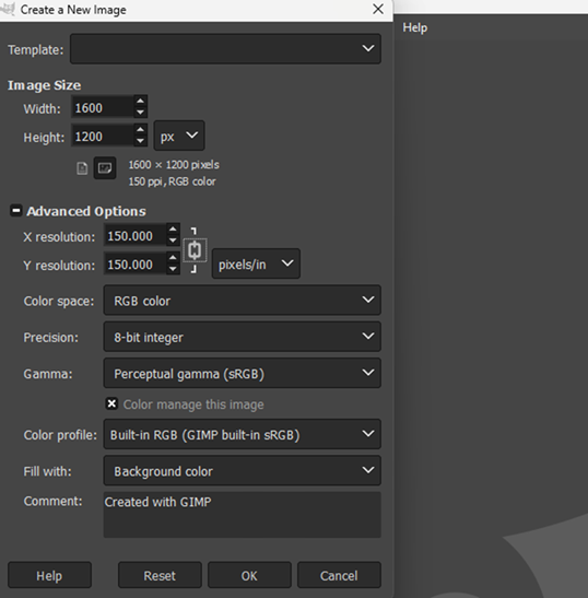
Create a New Project:
Navigate to the 'File' menu and select 'New' to start a new project.
Set your desired canvas size in the dialog box that appears.
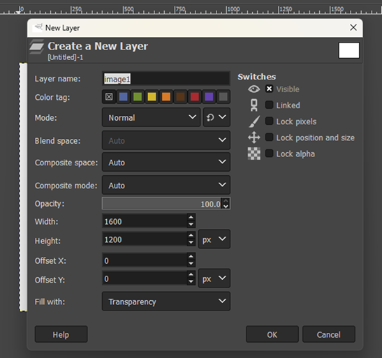
Create the New Layer:
Add a Background:
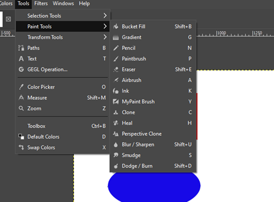
Choose the 'Bucket Fill Tool' from the toolbox.
Select a background color from the color palette.
Click on the canvas to fill it with the chosen color.
Applying the Paint Tools for Bucket:
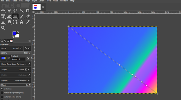
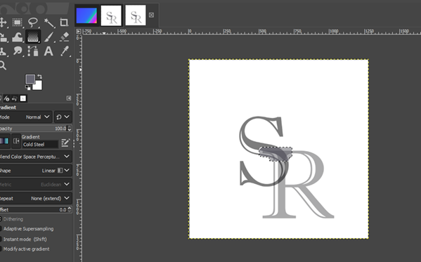
Applying Gradient Tool: Use the gradient tool under the menu "Paint Tool."
Insert Text:
Select the 'Text Tool' from the toolbox.
Click on the canvas where you want to add text.
Type your desired text.
Customize the font, size, and color using the tool options.
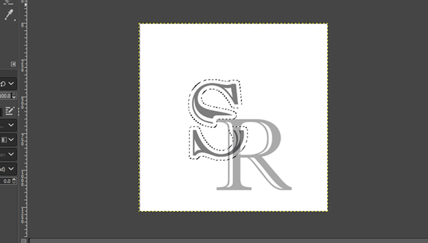
Apply Effects to Text:
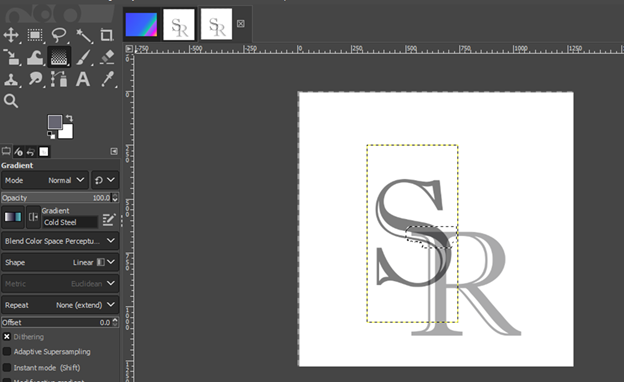
Right-click on the text layer in the 'Layers' panel and select 'Alpha to Selection' to select the text.
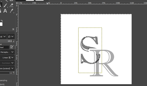
Navigate to the 'Filters' menu, choose 'Light and Shadow,' and then 'Drop Shadow' to add a shadow effect.
Adjust the shadow settings as desired and click 'OK.'
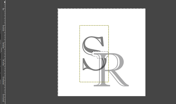
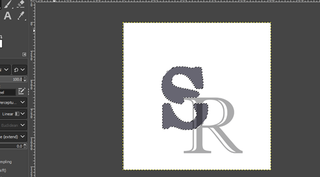
Selection and Alpha Selection:
Selection Options: None, Rectangle Select, Area Select
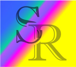
Once you're satisfied with your design, navigate to the 'File' menu and select 'Export As.'
Choose your desired file format (e.g., PNG, JPEG), name your file, and click 'Export' to save your logo.
2D vector: Welcome to InkScape
Simple Line Art Design
Step 1: Opening Inkscape
Launch the Inkscape application on your computer.
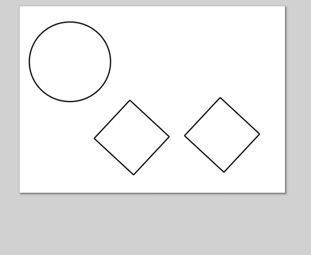
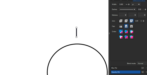
Step 2: Create a Circle or Ellipse
Use the Circle and Ellipse Tool to draw a shape. Set the fill color to black.
Step 3: Change the Color
Apply a black color to the shape if needed. With the help of stroke settings, the border line is filled with black color.
Step 4: Convert Object to Path
Select the shape and go to Path > Object to Path.
Step 5: Edit the Path
Press F2 to activate the Edit Paths by Nodes tool. Modify the shape by dragging or adjusting the nodes.
Step 6: Insert and Rotate a Square
Insert the shape of a square and rotate it to create a hill structure.
Step 7: Add Nodes
Add nodes to selected segments where needed to refine the shape.
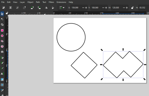
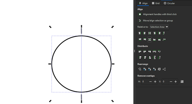
Step 8: Use the Align and Distribute Tool
Use the Align and Distribute tool to position elements precisely.
Step 9: Open the Fill and Stroke Panel
Open the Fill and Stroke panel to adjust color and stroke width.
Step 10: Set Stroke Width
Set the stroke color to black and stroke width to 5 px.
Step 11: Rotate the Object
Use the rotate function to adjust the orientation of the shape.
Step 12: Use Path Operations
Apply Path > Union to merge selected paths.
Step 13: Duplicate Objects
Press Ctrl + D to duplicate the selected object.
Step 14: Select Multiple Paths
Hold Shift and click to select multiple paths.
Step 15: Use Bezier Pen for Custom Shapes
Press Shift + F6 to activate the Bezier Pen tool. Draw and select the shape outside.
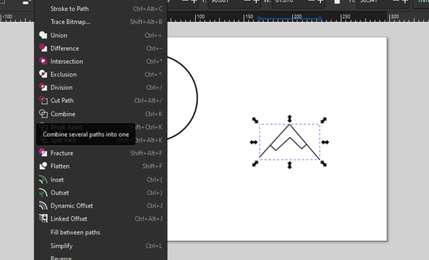
Step 16: Combine Paths
Select all paths and use Path > Combine to merge them.
Step 17: Create a Line
Create the line using the Bezier Pen tool to make the shape into sunshine. Align it using horizontal and vertical axes.
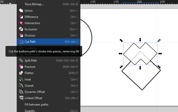
Step 18: Sunshine Axis
Create the sunshine axis with the help of the path option – Cut and Combine.
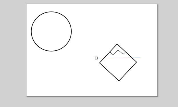
Step 19: Create Water Flow
Draw the horizontal line and convert it into water flow using the path option, cut and combine lines.
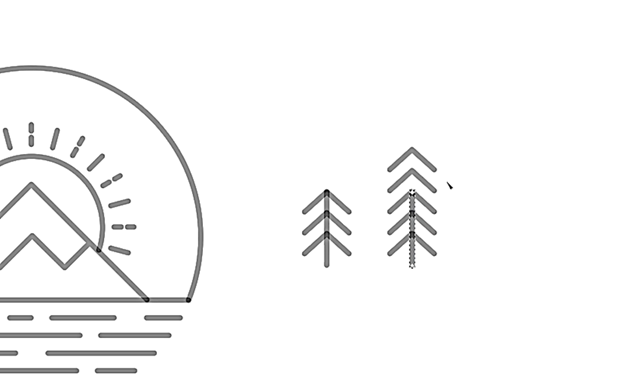
Step 20: Draw a Tree
Draw the tree using normal lines, convert it into a combined shape, and place it in the appropriate location.
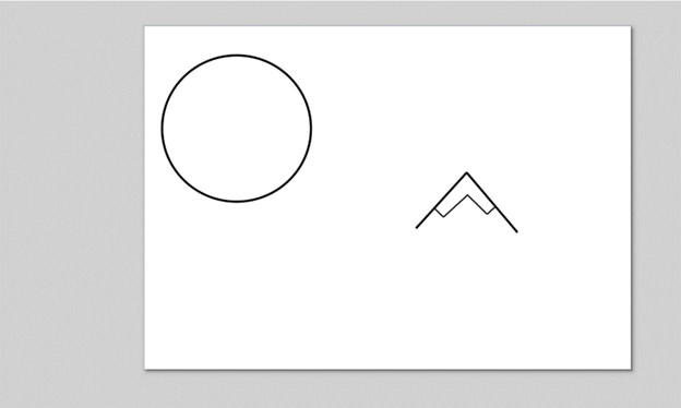
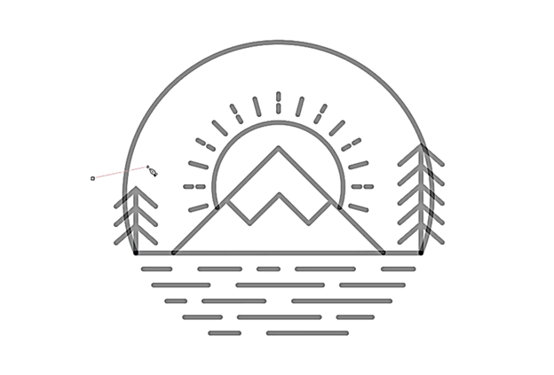
Final Art
The final art logo is created with the help of shapes and lines.
Comparison 2D raster and vector
Raster
Definition: A raster image is made up of tiny individual squares, called pixels.
Example: Digital photos, detailed artwork
Limitation: When you zoom in too much, the image becomes blurry and loses detail.
Best For: Realistic images or complex designs where resolution is important.
Vector
Definition: A vector image uses mathematical equations to create shapes like lines and curves.
Example: Logos, illustrations, icons
Limitation: Not as useful for realistic imagery like photos, as it’s based on simple shapes.
Best For: Designs that need to be resized without losing quality, like logos and graphics.
3D Design Software
Fusion 360 Software
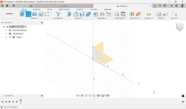
Step 1:
Firstly, Start Fusion 360 software, click on the Sketch option in Solid menu. Select the plane you need to create sketch on (we have choose front plane here).
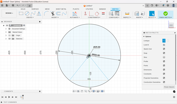
Step 2:
New Sketch menu will open. Click on Centre Diameter circle (or tap C button on your Keyboard) option to create circle on your workspace. Now create a circle from origin of diameter 500 mm and another circle of 25 mm diameter from same point. Draw two lines from center of circle to the circumference of the circle of 500mm.
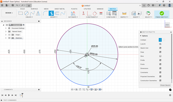
Step 3:
Click on Dimension (or tap on D on keyboard) in Create options in Sketch menu. Select the two lines and add the angle between them of 120°. Select Trim option in Modify option and select the major circle to trim, it will be highlighted in red colour.
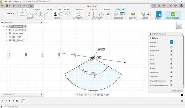
Step 5:
You will have this diagram. Click on finish sketch.
Step 6:
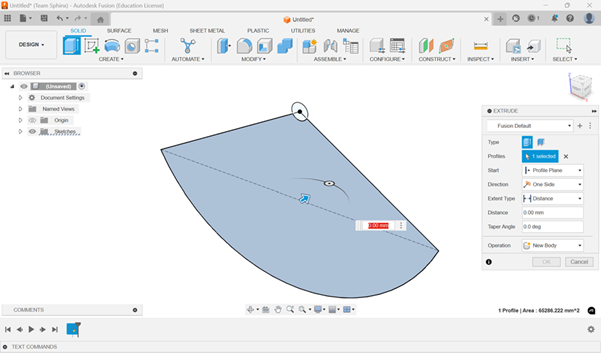
As you click on finish sketch, you will be directed back to the first workspace. Now click on Extrude option in Create Menu (or tap on E on Keyboard). Select the Region shown in figure and type in the value of 50. You will have a solid part of 50 mm thickness.
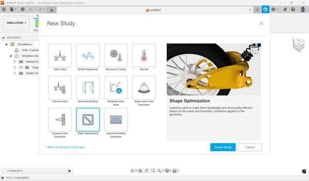
Step 7:
In Tool Bar, Click on Design. A dropdown menu will appear, Select Simulation. Your Workspace will shift from Design to Simulation. A window will appear, Select on Part optimization and click on Create Study.
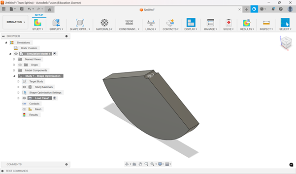
Step 8:
You will see your part on the workspace. Now click on structural constrain on constrain menu. A pop-up menu of structural Constrain will appear. Select the curve on top of the part and click OK. You will see a LOCK symbol to verify if the constrain is applied.
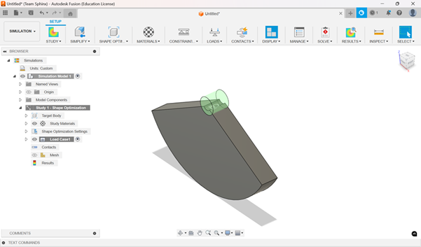
Step 9:
Click on Preserve Region in Shape Optimization menu. Select the curve, a green colored cylinder will appear, set the Boundary size of 25mm radius, click OK.
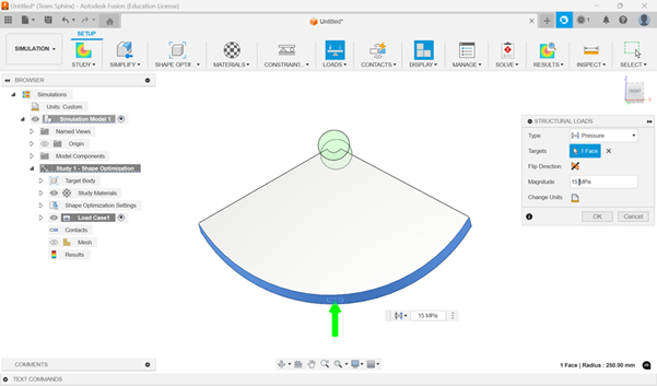
Step 10:
Click on Structural Load in Loads menu. Select the type as Pressure Load, apply the Magnitude of 10 MPa and click OK.
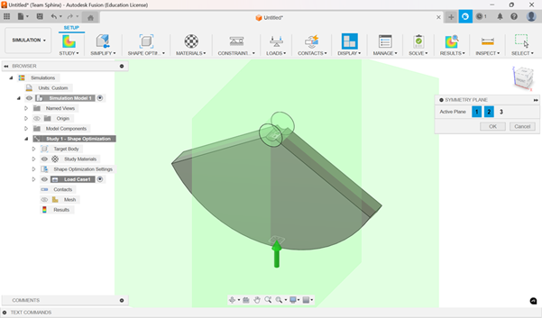
Step 11:
In Shape Optimization, click on Symmetry Plane. Select Front Face, in Symmetry Window select 1,2 planes.
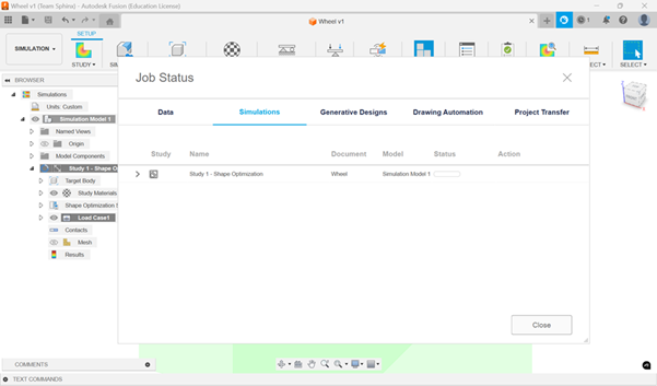
Step 12:
In Manage Menu, Click on Settings (or tap on E on keyboard). A Settings Window will appear, click on Mesh, adjust Model-based Size a bit. Click on OK, do a pre-check and click on Solve. After some time, you will see the Result window.
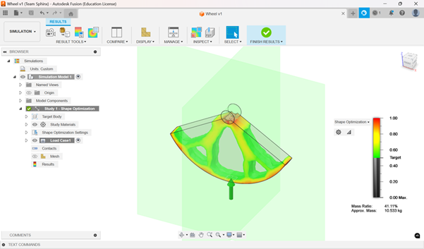
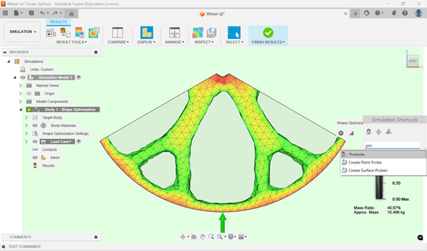
Step 13:
You will see the below Result.
Step 14:
Click on workspace and tap S on keyboard, search dialog will appear, search for Promote option and click on it.
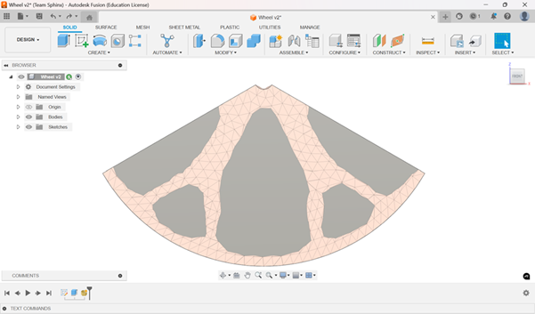
Step 15:
The workspace will convert back to Design Workspace. And below figure will appear.
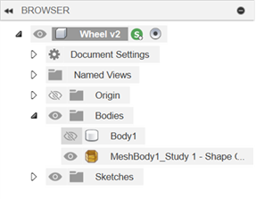
Step 16:
Turn OFF visibility of Body1 from Browser.
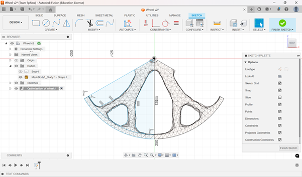
Step 17:
Click on the Browser and create new component, name it as Optimization of Wheel. Create a new sketch and trace out half of the wheel using Line command.
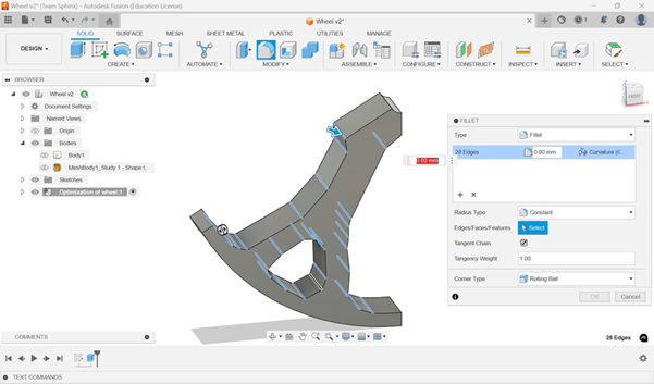
Step 18:
Extrude the traced-out part of thickness 50mm, and add fillet to edges to smooth out the body.
Step 19:
After Completing fillet, mirror the component.
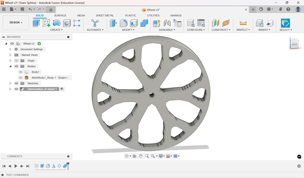
Step 20:
Now use circular pattern and make a complete wheel. Use Combine option to Join the new segments to make it a single component.
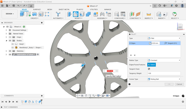
Step 21:
Again Use Fillet to the inside of the wheels. Here we took fillet of 10 mm.
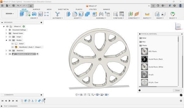
Step 22:
Now add Physical Material to the component. To add Physical Material, tap on S to open search window and then type “Physical Material”. A side window will be open with a list of multiple materials. In the plastic section, click and hold on to ABS Plastic then drag and drop to the component.
I m belongs to non mechanical background, learned with the help of Akash Instructor and Kadam sir. Sincere thanks for their support