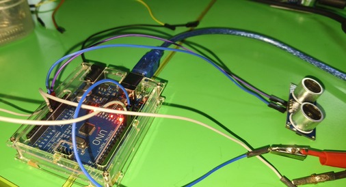
Ultrasonic Sensor
This sensor measures distance by emitting sound waves and calculating the time it takes for them to bounce back. It is commonly used in parking systems, obstacle detection, and robotics.
The HC-SR04 ultrasonic module stands out for its expansive detection range, spanning from 2cm to 400cm , with a remarkable accuracy of up to 3mm. Consequently, it proves to be particularly well-suited for scenarios that demand precise distance measurements.
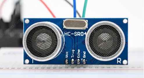
- VCC supplies power to the HC-SR04 ultrasonic sensor. You can connect it to the 5V output from your Arduino.
- Trig (Trigger) pin is used to trigger ultrasonic sound pulses. By setting this pin to HIGH for 10µs, the sensor initiates an ultrasonic burst.
- Echo pin goes high when the ultrasonic burst is transmitted and remains high until the sensor receives an echo, after which it goes low. By measuring the time the Echo pin stays high, the distance can be calculated.
- GND is the ground pin. Connect it to the ground of the Arduino.
Pin Details
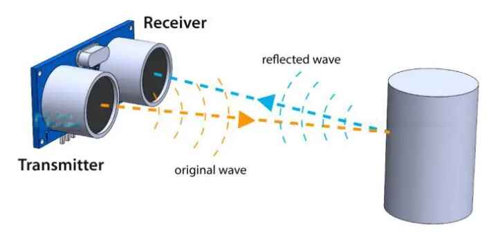
It all starts when the trigger pin is set HIGH for 10µs. In response, the sensor transmits an ultrasonic burst of eight pulses at 40 kHz. This 8-pulse pattern is specially designed so that the receiver can distinguish the transmitted pulses from ambient ultrasonic noise.
These eight ultrasonic pulses travel through the air away from the transmitter. Meanwhile the echo pin goes HIGH to initiate the echo-back signal.
If those pulses are not reflected back, the echo signal times out and goes low after 38ms (38 milliseconds). Thus a pulse of 38ms indicates no obstruction within the range of the sensor.
Calculating the Distance
The width of the received pulse is used to calculate the distance from the reflected object. This can be worked out using the simple distance-speed-time equation we learned in high school. An easy way to remember the equation is to put the letters in a triangle.
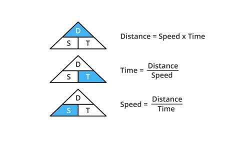
Let us take an example to make it more clear. Suppose we have an object in front of the sensor at an unknown distance and we receive a pulse of 500µs width on the echo pin. Now let’s calculate how far the object is from the sensor. For this we will use the below equation.
Distance = Speed x Time
Here we have the value of time i.e. 500 µs and we know the speed. Of course it’s the speed of sound! It is 340 m/s. To calculate the distance we need to convert the speed of sound into cm/µs. It is 0.034 cm/μs. With that information we can now calculate the distance!
Distance = 0.034 cm/µs x 500 µs
Remember that the echo pulse indicates the time it takes for the signal to be sent and reflected back. So to get the distance, you have to divide your result by two.
Distance = (0.034 cm/µs x 500 µs) / 2
Distance = 8.5 cm
Now we know that the object is 8.5 cm away from the sensor.
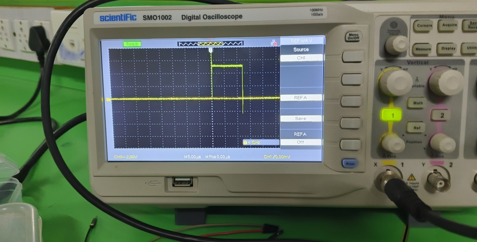
We connected the trigger pulse pin to the DSO to observe its response. By carefully probing the signal, we were able to see the waveform, gaining insights into its behavior and characteristics. This process allowed us to understand the interaction between the trigger pulse and the oscilloscope's display, providing valuable data for our assignment.
We observed the trigger pulse on the Arduino board and measured its corresponding response on the echo board. By analyzing the signals on both boards, we gained a better understanding of the interaction and timing relationships of voltage pulse between the components.
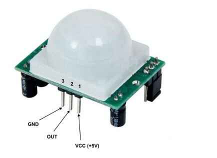
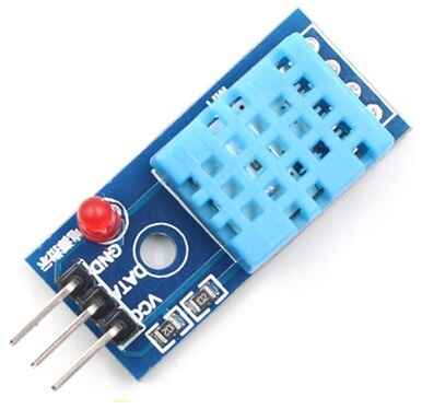
DTH 11 Sensor
DHT11 Module features a temperature & humidity sensor complex with a calibrated digital signal output. The exclusive digital-signal-acquisition technique and temperature & humidity sensing technology ensure high reliability and excellent long-term stability. This sensor includes an NTC for temperature measurement and a resistive-type humidity measurement component for humidity measurement.
The DHT11 module has a total of 3 pins. In which two are for power and one is for communication. The pinout of a DHT11 Sensor module is as follows:
Similary we used the multimeter and observe the voltage in the data pin when it shorted with ground
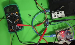
Damaged sensor module shows the Zero '0' voltage on the out/data pin, observed commonly
During our observation of the DTH sensor while it was communicating with the Arduino, we noticed that it exhibited a response influenced by a delay. This response was characterized by the generation of square-like pulses. These pulses seemed to reflect the sensor's data transmission behavior, providing us with an interesting insight into its operation and timing dynamics.