Study of PCB Production Process
This week, Dr. Shantanu Kadam and I visited a fabrication lab to learn the complete PCB production process hands-on. We began by designing circuit boards using KiCad software and MIT MODS, where we carefully laid out copper traces and marked component positions. The real excitement came when we transferred these digital designs to physical boards using a CNC milling machine. Working with FR4 material gave us insight into commercial PCB manufacturing standards, as this is the material used in most consumer electronics.
PCB Material: FR4 (Fiberglass Epoxy)
FR4 is the most widely used material for printed circuit board substrates. It consists of a woven fiberglass cloth impregnated with flame-resistant epoxy resin, creating a strong and durable composite. The material is typically light green in color (due to the solder mask) but appears yellowish or translucent in its raw form.
As a fiber-reinforced plastic, FR4 offers superior mechanical and electrical properties compared to phenolic-based materials (like FR1/FR2). Its key advantages include:
FR4 is the industry standard for most commercial PCBs, including multilayer designs, due to its balance of performance, cost, and manufacturability. It is used in everything from consumer electronics to industrial equipment, where reliability under thermal and mechanical stress is critical. The "FR" designation indicates its flame-retardant properties, meeting UL94 V-0 standards for fire safety.
The UL94 V-0 standard is a flammability test used to classify the self-extinguishing time of vertically oriented plastic specimens.
Mill Drill Machine for PCB Drilling, Milling and Routing Application
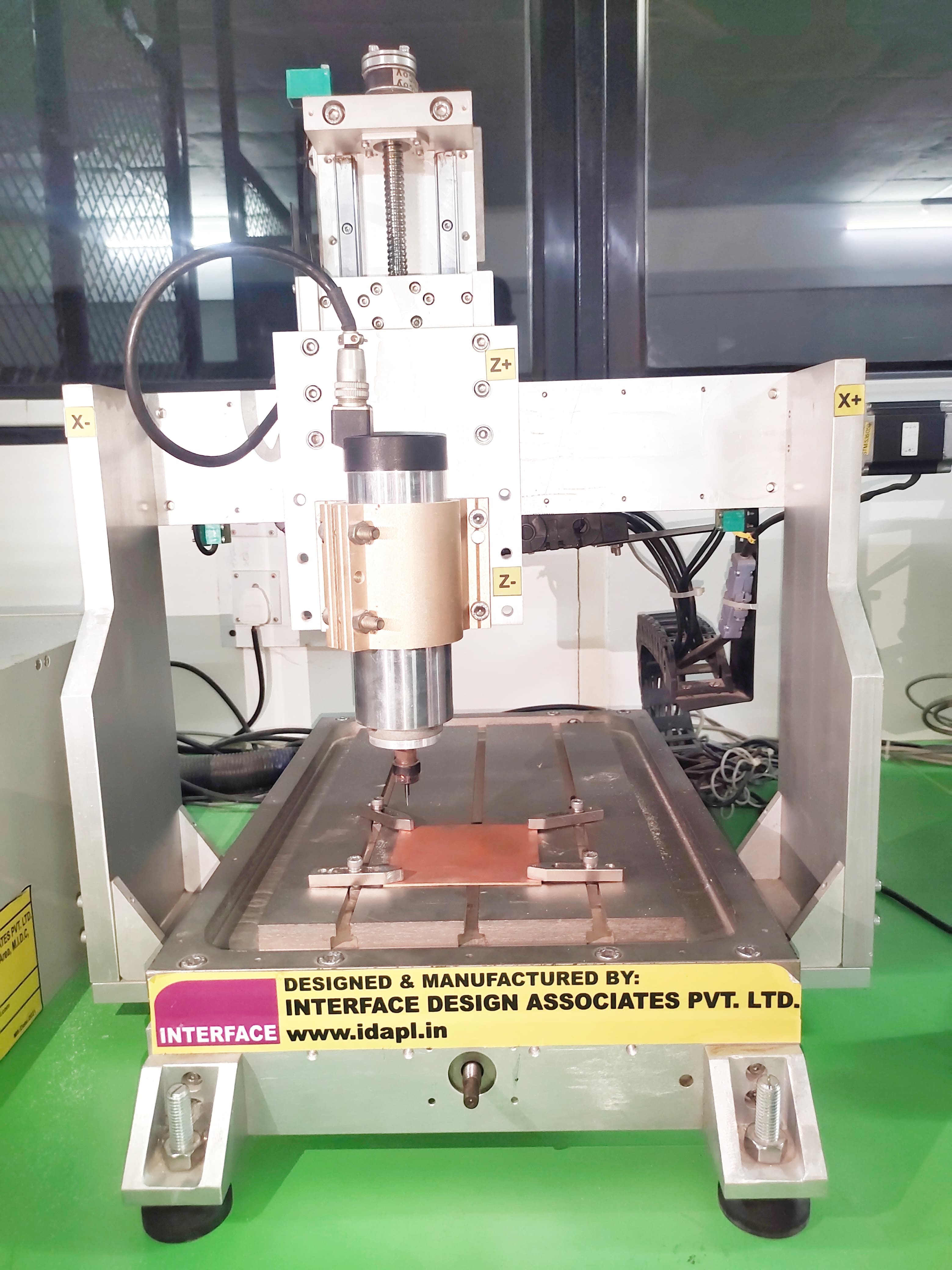
The manufacturer of the machine is Interface Design Associates Pvt. Ltd., a local manufacturer in India. Additionally, we are utilizing the WinMill, which combines the power of the SC06 with a user-friendly application running under the Windows 7/8/8.1/10 32-bit system. The SC06 card is a three axis CNC controller which is highly cost effective controller with following features:
• 4 Axis of digital numerical control• G & M Code support
• Multiple Operation Modes.
• Manual Mode - Jog, Incremental, Absolute and Home.
• PLC Interface available
• 16 digital inputs and 16 digital outputs. (Additional RemIOV4 card with serial port comm.)
The CNC controller is a standard PC running Microsoft Windows. The motion is controlled through the SC06 card and the IOs are through an intelligent IO board (SC04 BOB ISO ). The PLC system forms a part of the CNC application and the PLC ladder logic program and the GCODE programs are coordinated.
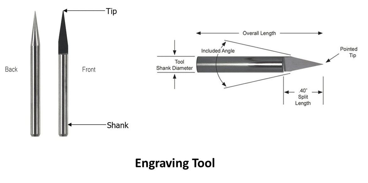
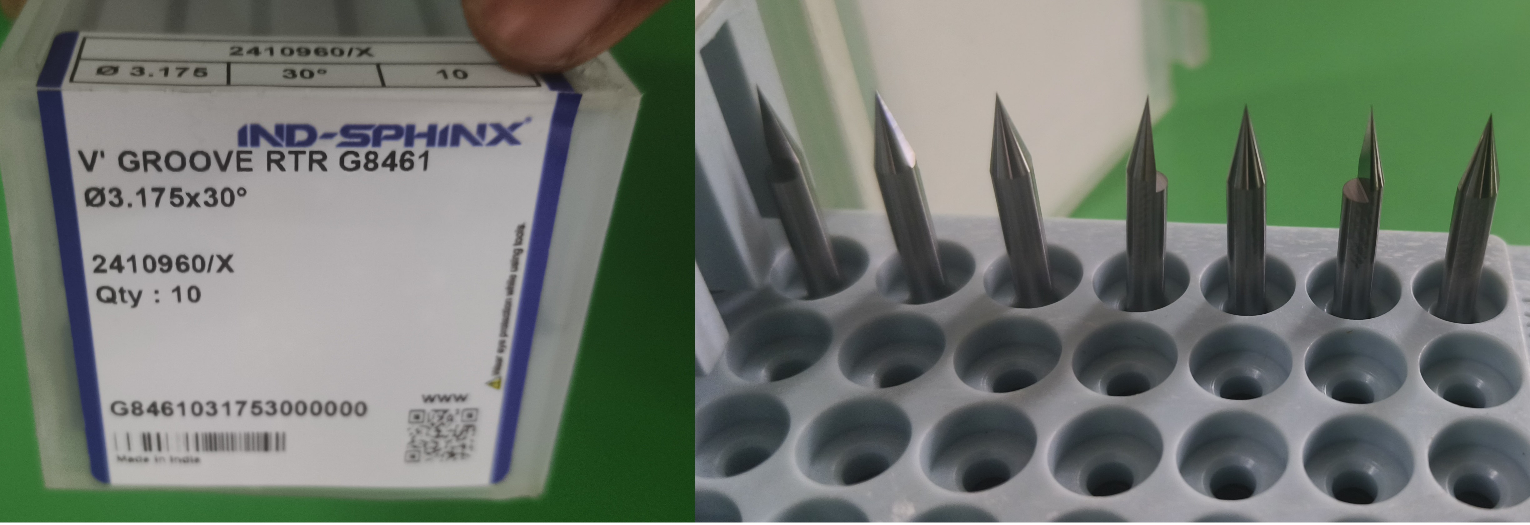
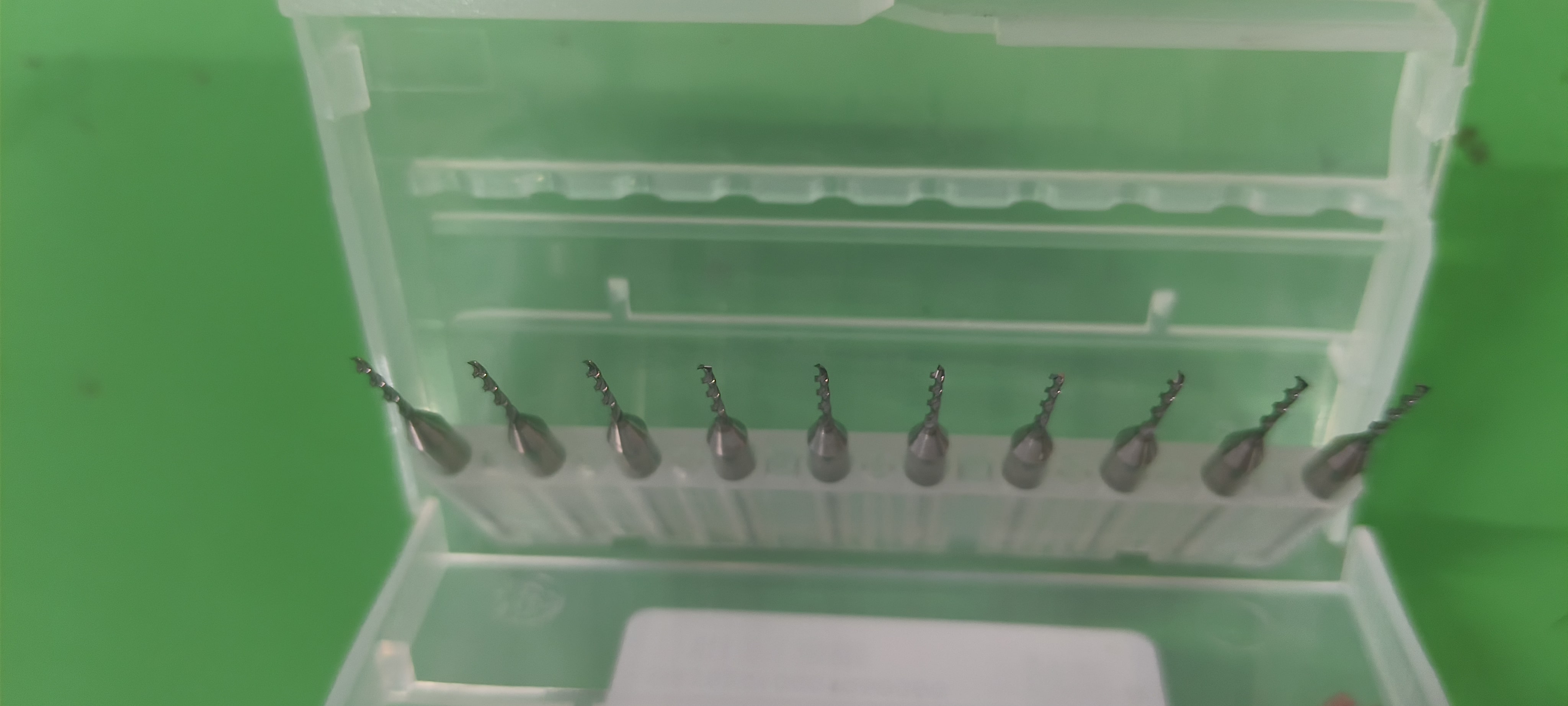
PCB milling (Engraving) Tool:
Engraving tools are available in different shank diameter, different tip diameter and also with different split angles. There are also coated and uncoated tools. Coated tools have double life as compared to uncoated tools in normal operation.
PCB edge cut tools, often referred to as "edge cuts" or "board outline," are graphical lines that define the physical shape of a printed circuit board (PCB).
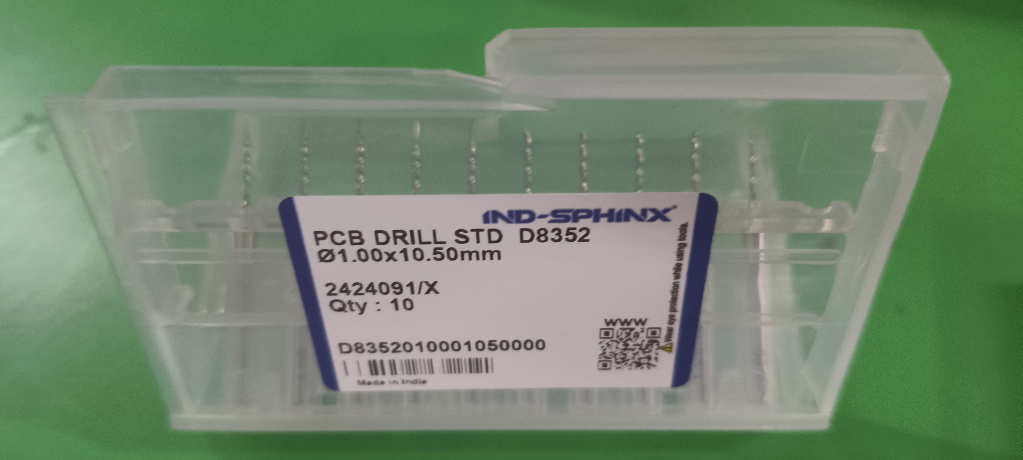
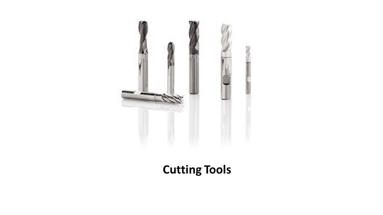
Routing Tool:
Routing tool is called as End Mill. These tools are also available in different shank sizes and different nosal diameter. There is flat end mill and ball end mill; user can use these tools depending upon their application.
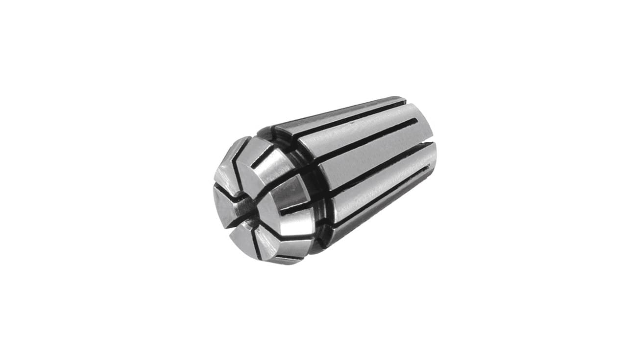
Collet:
Spindle of MM3030 is with ER11 Collet, therefore always use ER11 collet for MM3030 machine. ER11 series collets have a capacity of 0.020-0.3125 inches. Each ER11 collet has a range of 0.020 inches (0.5mm). The size indicated on the collet is the largest size it can hold and can be collapsed smaller within its collapse range of 0.020 inches (0.5mm). For example, ER11-3mm can grab a round shank from 3mm diameter to 2.5mm diameter.
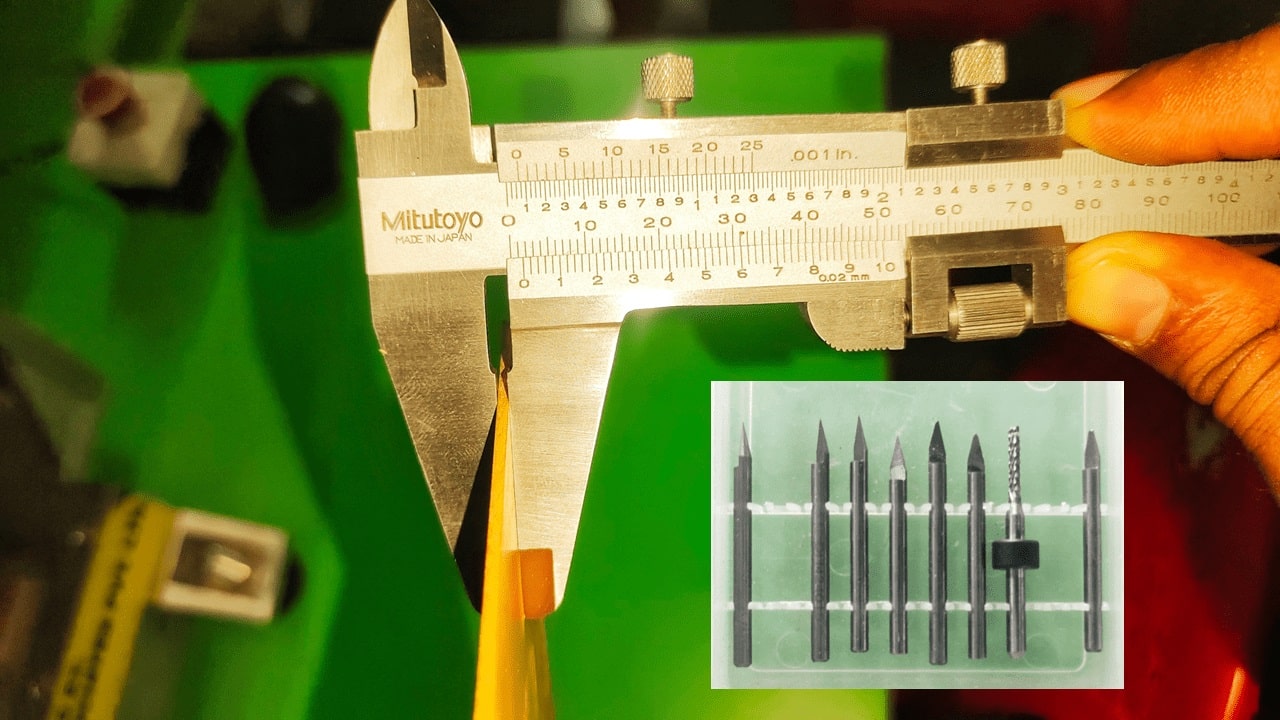
Mr.Akash Mhais gave a lecture about the PCB milling machine, then i fix the tool into the spindle properly
We measured the thickness of the sheet to determine and set the maximum depth of the tool.
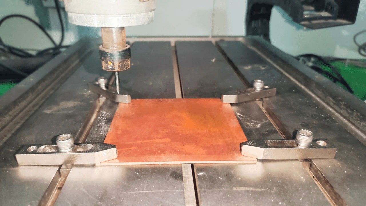
We fixed the sheet using clamps on the workbench, which is a crucial step. Uneven fixing of the material can result in incorrect traces, potentially leading to defects in the PCB.
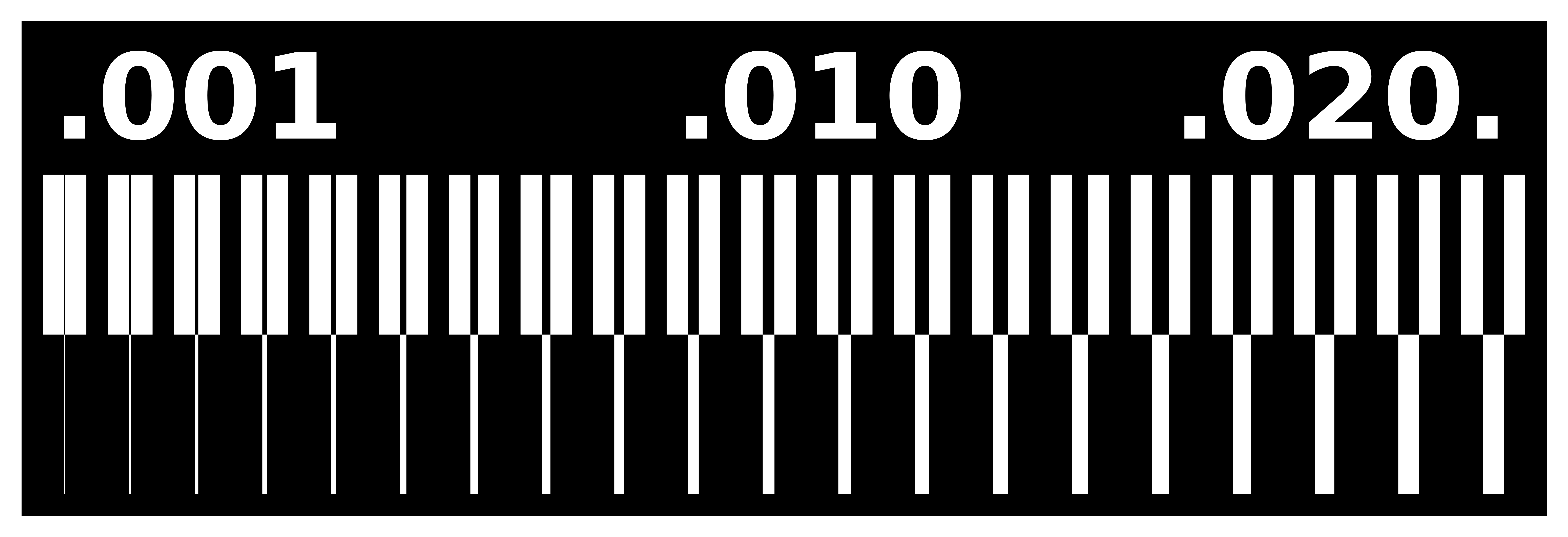
Then Downloaded the given traces from the fab academy link Fab Academy PCB milling.

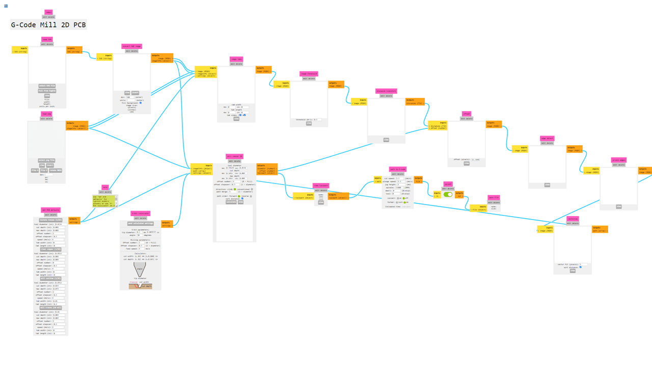
To generate the G-code for PCB milling, we used the online MODS interface developed by MIT's Center for Bits and Atoms (available at modsproject.org. The process was straightforward: First, I right-clicked anywhere on the blank workspace to open the context menu, which displays various modules and options. From there, I selected "Programs" and then chose the "mill 2D PCB" option from the list of available machining operations. This automatically loaded the complete PCB milling workflow into the interface, with all the necessary modules connected in the proper sequence for generating toolpaths. The web-based MODS platform made it easy to prepare our milling files without needing any specialized software installed on our computers.
Following steps are followed to convert png file to .nc file
In this program, we can import two types of file formats: .svg and .png. In our case, we will be using the .png file format. After opening the file, go to "Set PCB Defaults" and select the mill outline (1/32).
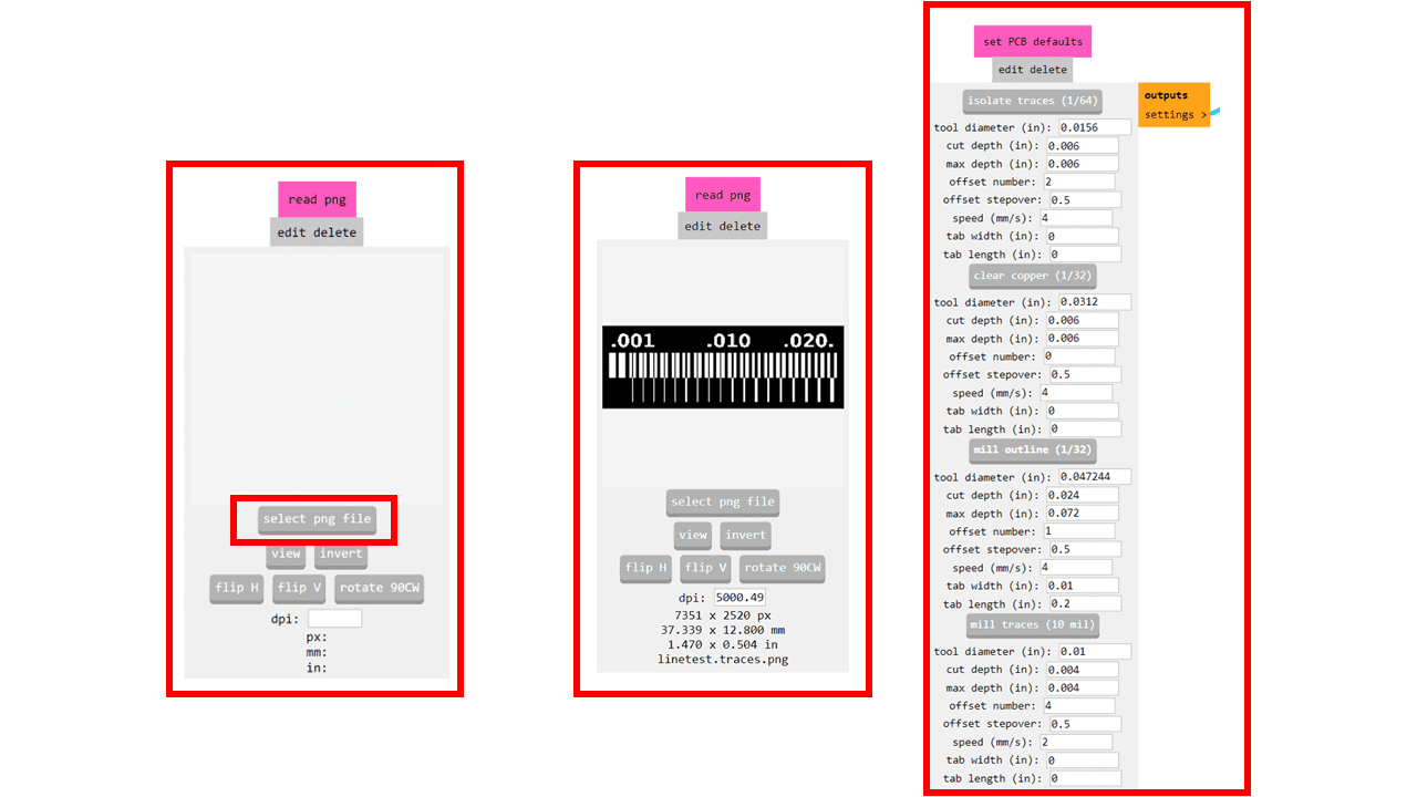
After selecting the mill outline (1/32), proceed to "Mill Raster 2D." Here, we can adjust the tool diameter, cut depth, and the maximum depth of the tool. Then, click on the "Calculate" option. The code file will be downloaded, and we can view the traces by clicking on the "View" button.
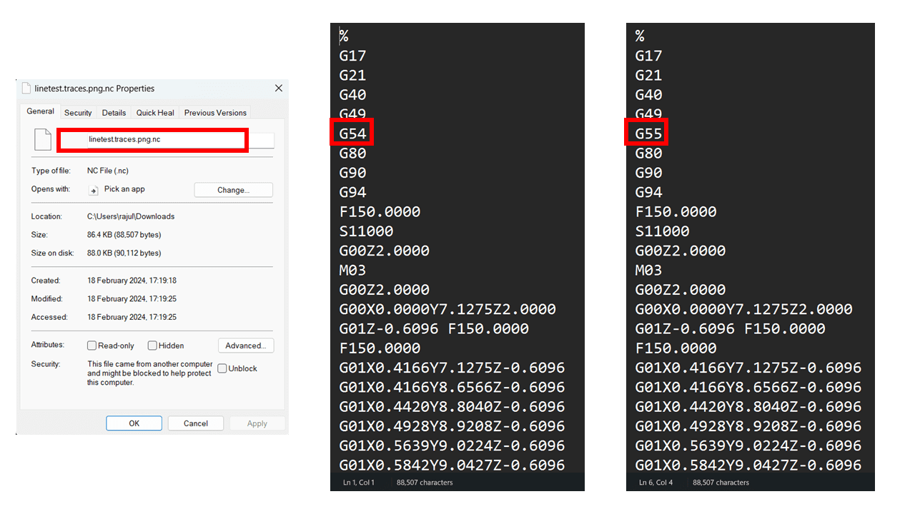
The downloaded file is in the format of .nc. In our case, we have to change the extension of the file from .nc to .gcd for compatibility with our software and the machine. Additionally, we edit the file and make some changes in the G-code, such as changing from G54 to G55.
This is the interface of the software used for the PCB milling machine, which is provided by the local manufacturer of our fab lab's PCB milling machine.
The information displayed is:1. Idle mode of the machine displayed
2. Machine status consisting of the following parameter is displayed:
X, Y, Z and A axis co-ordinates
Feed rate, Override, Dry run, Single step, Retrace, Optional Stop, Block Skip
Spindle ON/OFF and Coolant ON/OFF
Cycle Start and Cycle Hold
Load, Reload, Preview and Reset And Jog control section.
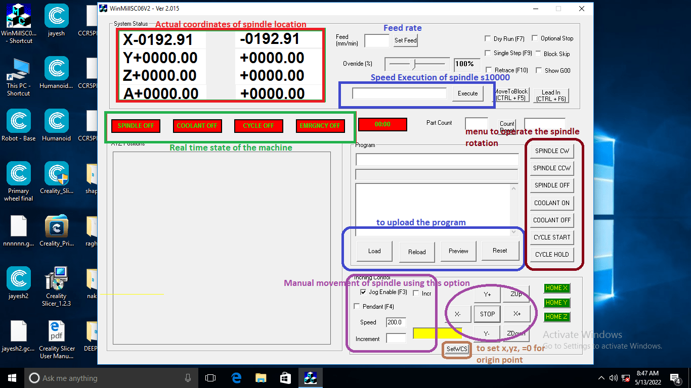
Manual Movement: Manual movement is provided as a sub menu of play menu, used to set the spindle in origin . Click on Jog Enable on the play screen to enter into the jog menu. There are three options for Jogging:
1. Jog Enable: Once Jog Enable is selected, the mechanism moves in the direction specified by pressing the buttons X+, X-, Y+, Y-, ZUp or ZDown. The movement stops only when the STOP button is pressed. The speed of movement is the speed specified in the Speed option in mm/min. The default speed is 200 mm/min.
2. Incremental: When incremental motion is selected, the mechanism will move with the specified speed only for the distance specified in the Increment option.
Indication Window: In indication window it will indicates the status of Spindle, Coolant, Cycle ON/OFF, Emergency ON/OFF, Cycle time. For OFF condition it will indicate in Red colour for respective status tab and for ON condition it will indicates in Green colour. In "Part Count" dialog box it will show cycle counts, the count will increment after completing every cycle. To reset part counts use "Count Reset" button.
Emergenecy push butto The emergency push button is activated in the event of a software or hardware malfunction to immediately halt the spindle and prevent potential damage.
CONTROL MENU: The Control Menu is used to control Inputs & outputs like Spindle ON/OFF, Coolant ON/OFF, Cycle Start, Cycle Hold. User can turn ON the Spindle by using buttons "SPINDLE CW" for clockwise direction and "SPINDLE CCW" for counter clockwise direction, to Turn OFF the Spindle press "SPINDLE OFF" button. Similarly for Coolant ON/OFF press "COOLANT ON"/"COOLANT OFF". For Cycle starts and Cycle hold use "CYCLE START" and "CYCLE HOLD" buttons.
This is Work Offset setting in which we can set the co ordinates of the spindle
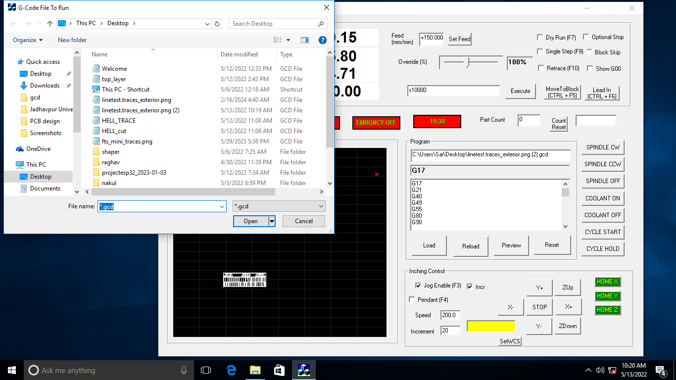
Upload the trace using load option in sotware window. On the display, it will show the toolspath of the real-time operation of the machine.
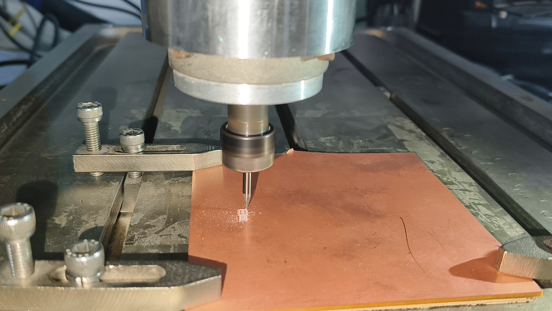
PCB Engraving on our machine
Upload the external outline-edgecut layer using load option in sotware window. On the display, it will show the toolspath of the real-time operation of the machine.
This is the output i got from the milling machine.
Shots of group learning along with my instructor
Learning outcomes
We learned to use MIT Mods, a free online tool designed for generating PCB milling files. This tool simplifies the process of creating G-code, converting design files into machine instructions. One of the most convenient aspects of MIT Mods is that it operates entirely in a web browser, eliminating the need for software installation. The workflow is user-friendly—just right-click, select "mill 2D PCB," and follow the guided steps. This makes it especially helpful for beginners, as it demystifies the complexities of PCB milling. With this newfound knowledge, I am now equipped to create milling files for my own PCB designs, making the process both efficient and accessible.
Thanks to our instructor Mr.Akash Mhais for providing support
🙂 Happy Group Learning 🙂
🙂 Sujith Mayakrishnan 🙂