SANJIVANI FAB LAB
Week 6: Electronic Design
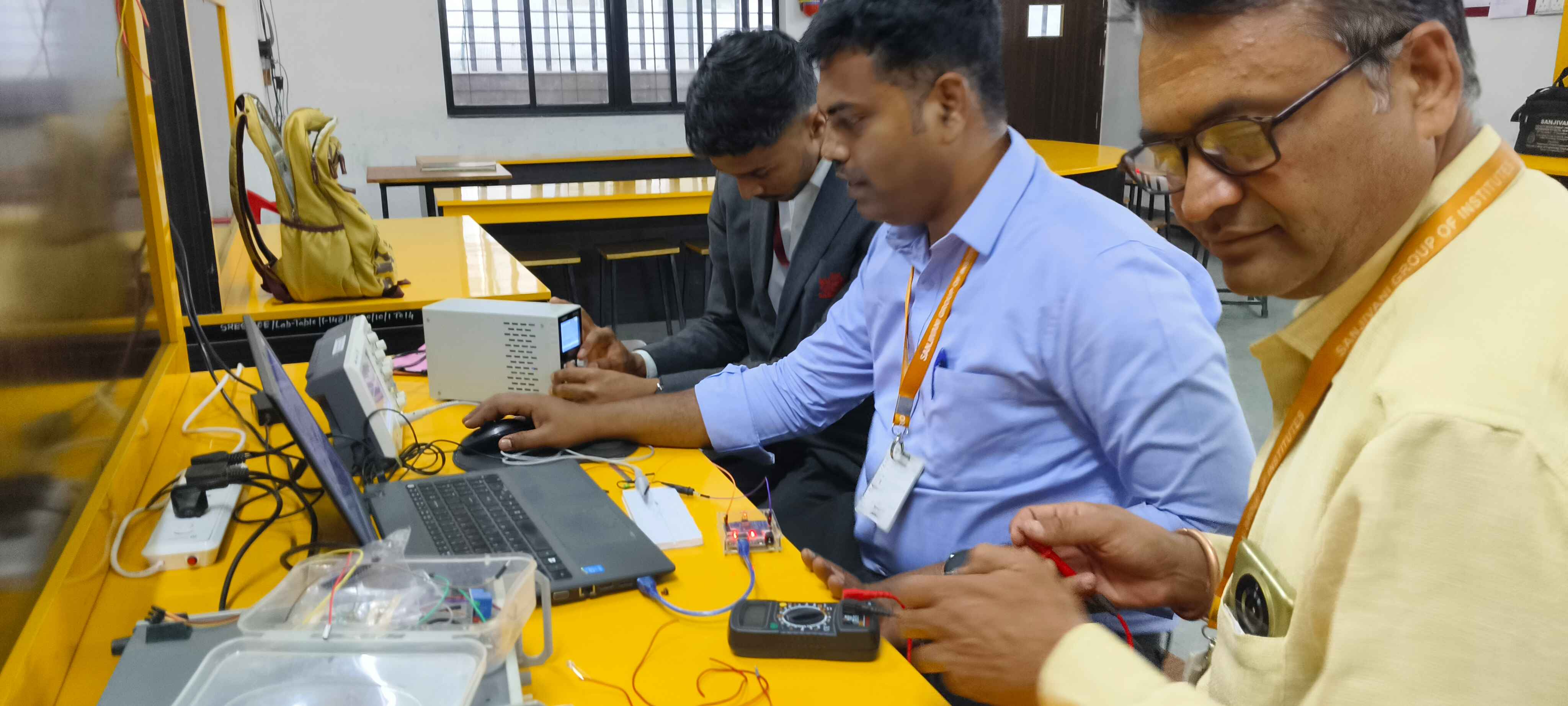
Group Assignment
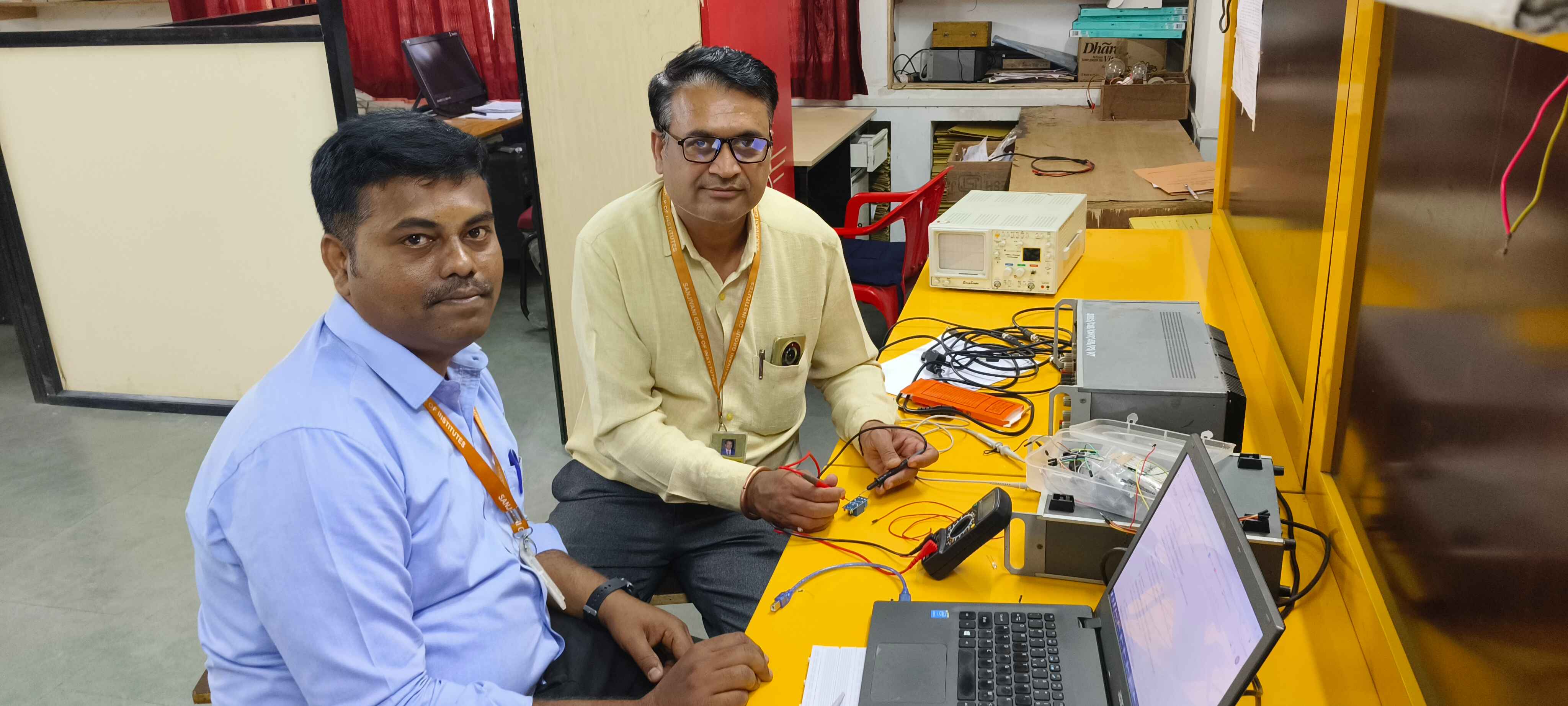
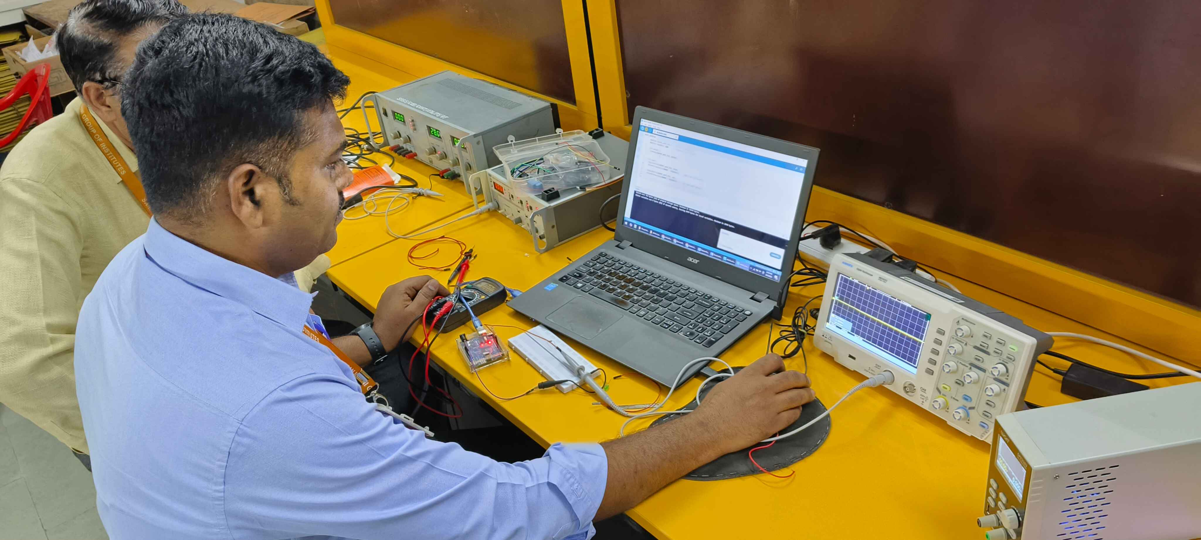
Use the test equipment in your lab to observe the operation of a microcontroller circuit board
In this asssignment we have taken available equipment in our lab
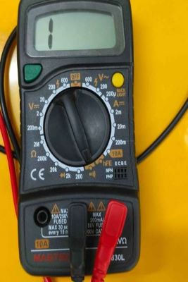
It is hard to say exactly which characteristics a multimeter should have, since there are different needs depending on the background of the user and the intended usage, but let's say that independently of the level of the user, a multimeter should have:
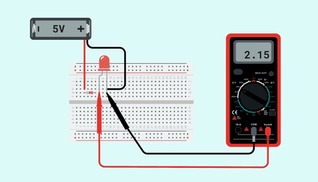
The image below shows how to read the voltage falling in an LED. In order to know the voltage falling on a component, you will need to connect the multimeter in parallel with it.
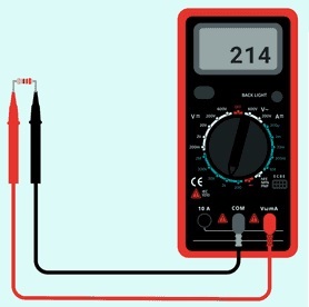
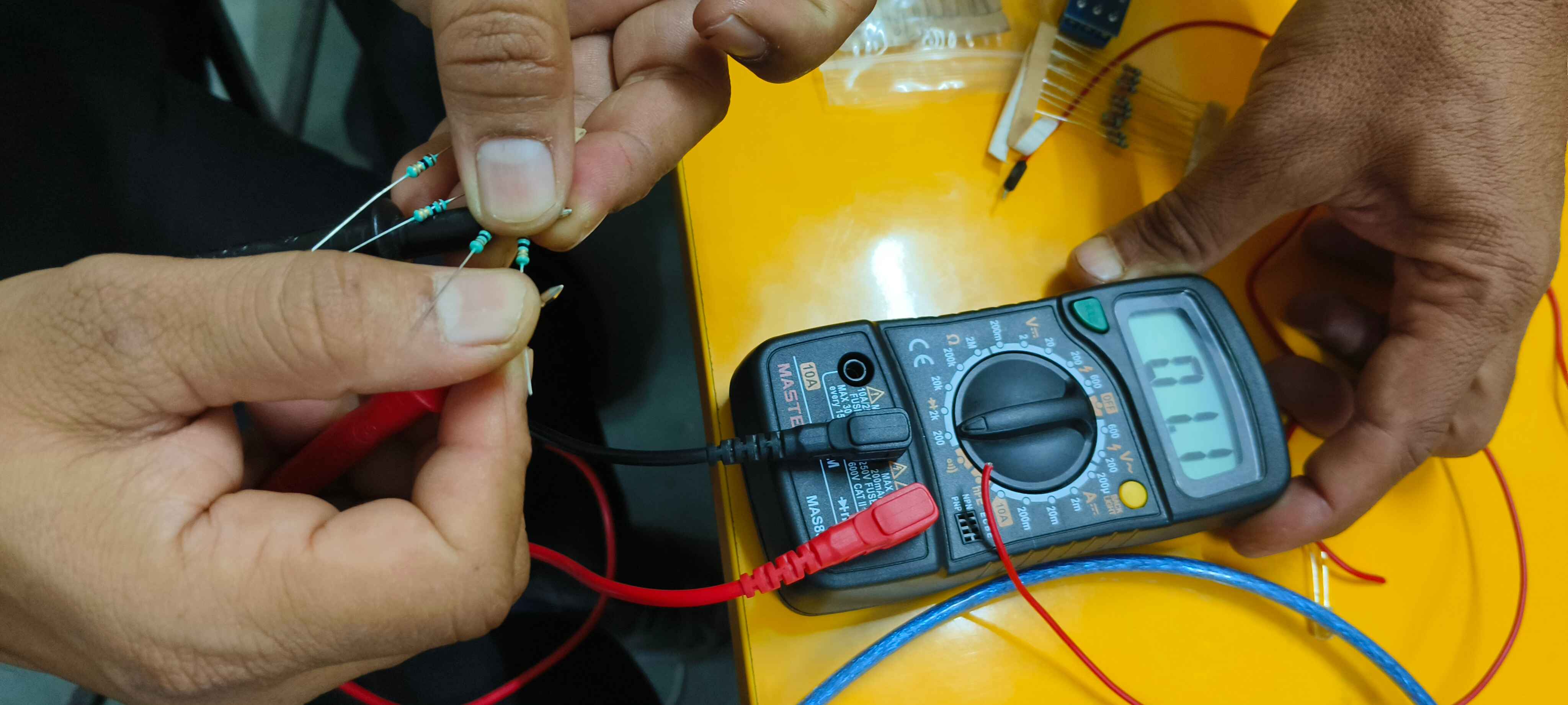
In order to know the value of a resistor, you need to keep in mind that the measurement must be done on a resistor that is not connected to any other component! Then, you can make the reading:
Place each one of the terminals of the multimeter in each one of the terminals of the resistor.
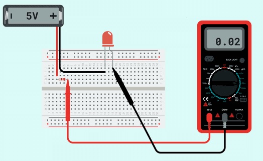
 The image below shows how to read the current flowing through a circuit with a LED and a resistor. Here, you can see how the multimeter is connected in series with the resistor and the LED, as if it was one more component of the circuit.
M4
The image below shows how to read the current flowing through a circuit with a LED and a resistor. Here, you can see how the multimeter is connected in series with the resistor and the LED, as if it was one more component of the circuit.
M4
 Continuity Test in relay
Then, depending on the user background, there will be some features that could make the multimeter easier to use, or make it a more complex tool. Some of these features are:
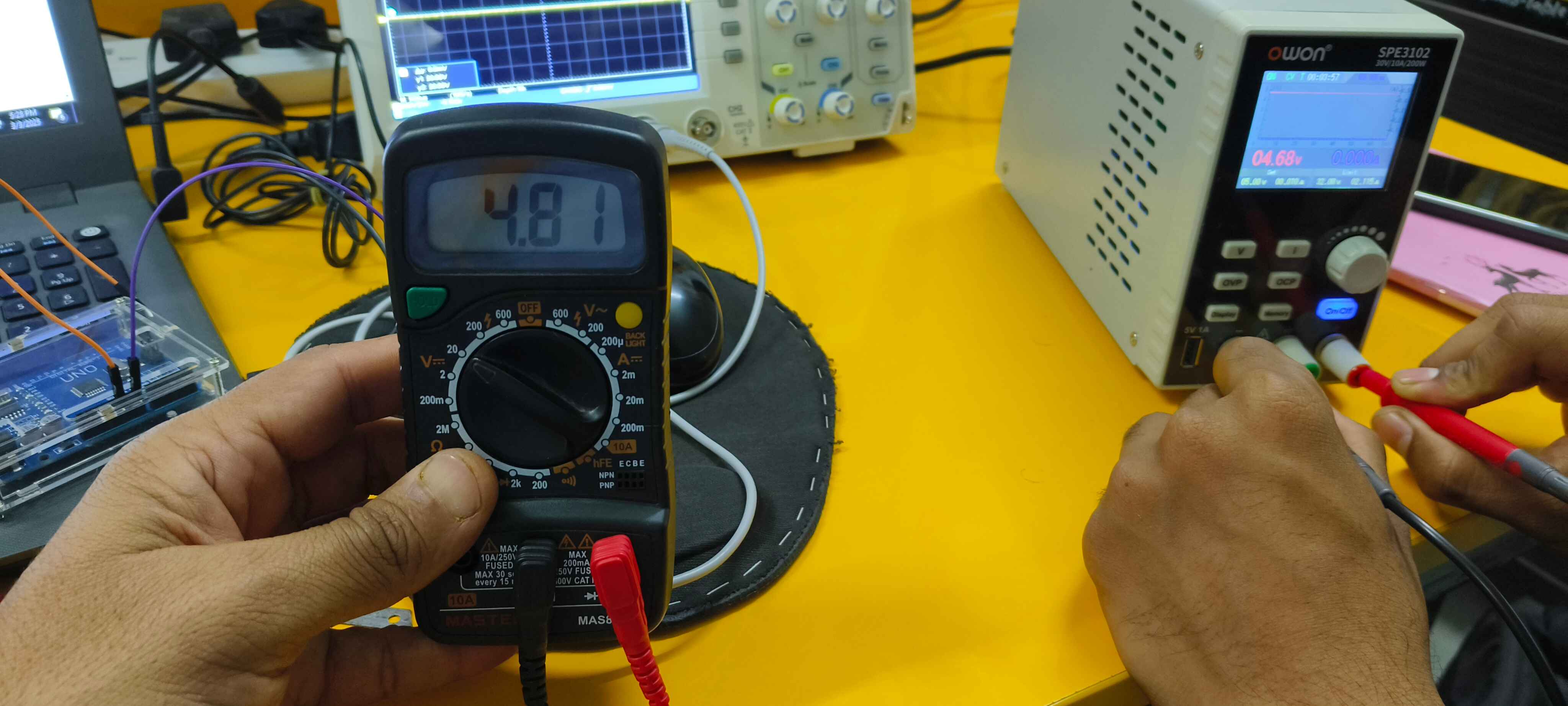
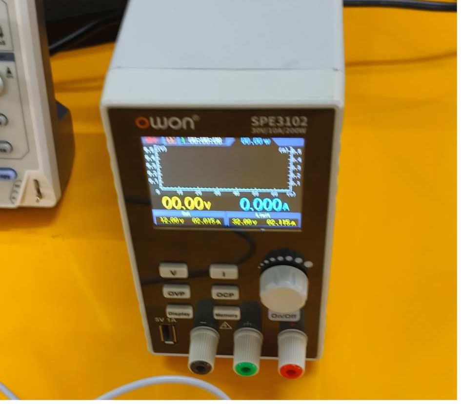
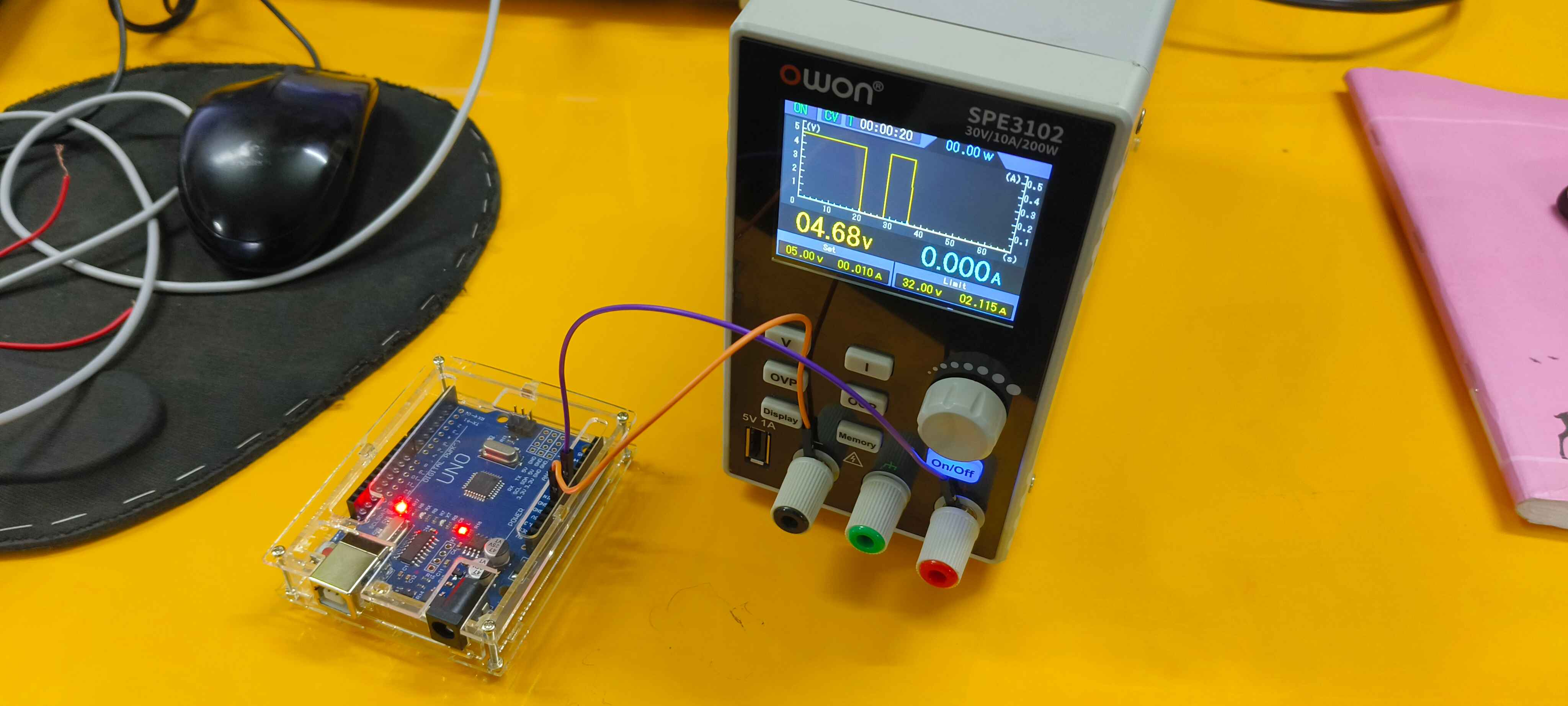
Arduino can be powered in three ways: using USB, Jack, and Vin. In our setup:
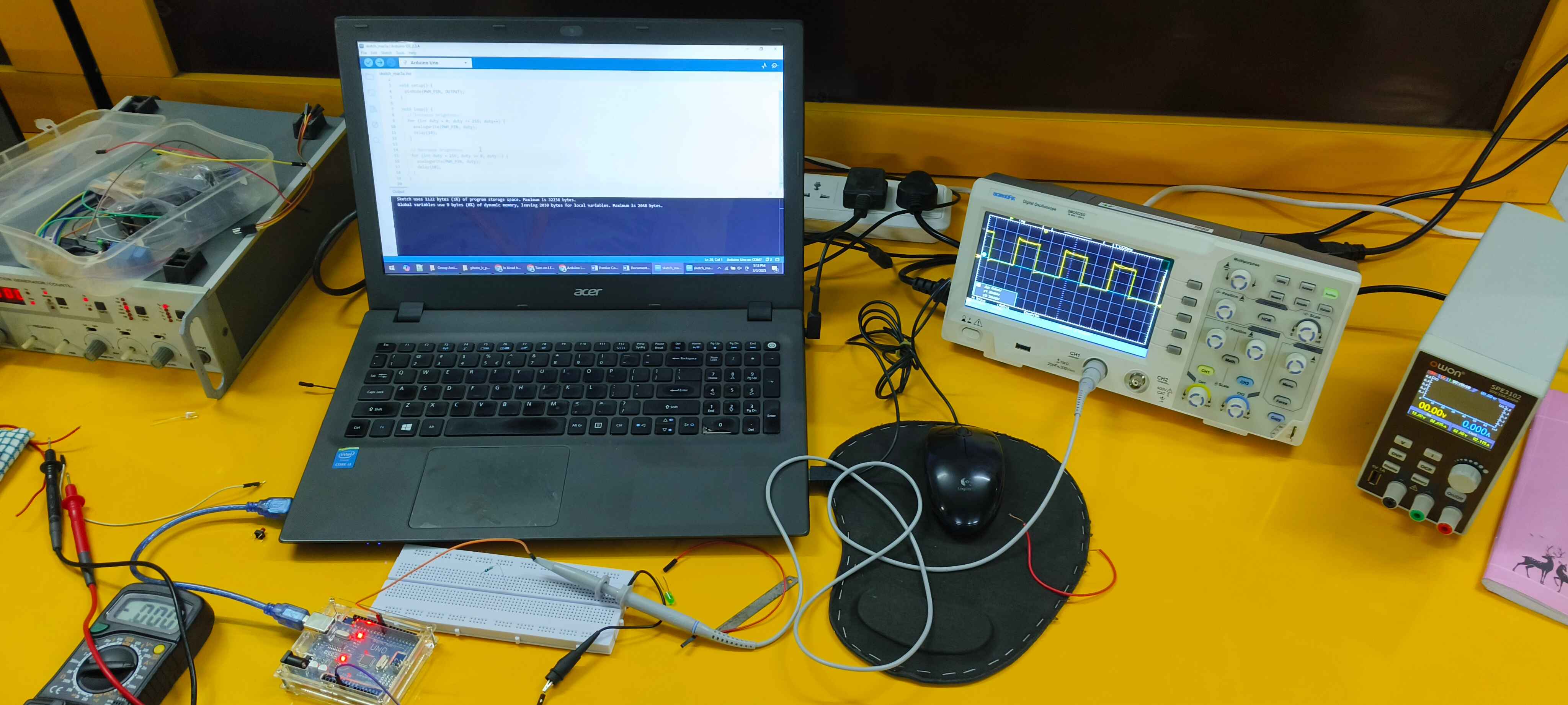
A digital storage oscilloscope (DSO) is a device that measures and records electrical signals
The digital storage oscilloscope works in three modes of operations they are roll mode, store mode, and hold or save mode.Features:
Code for LED fading intensity levels:
To generate the PWM pulse in Arduino we wrote the code of Simple led fading of intensity levels. Connecting the aduino pin D9 and Gnd to the oscilloscope
#define PWM_PIN 9
void setup() {
    pinMode(PWM_PIN, OUTPUT);
}
void loop() {
    for (int duty = 0; duty <= 255; duty++) {
        analogWrite(PWM_PIN, duty);
        delay(10);
    }
    for (int duty = 255; duty >= 0; duty--) {
        analogWrite(PWM_PIN, duty);
        delay(10);
    }
}
#define SQUARE_WAVE_PIN 9
#define FREQUENCY 1000
void setup() {
    pinMode(SQUARE_WAVE_PIN, OUTPUT);
}
void loop() {
    digitalWrite(SQUARE_WAVE_PIN, HIGH);
    delayMicroseconds(500000 / FREQUENCY);
    digitalWrite(SQUARE_WAVE_PIN, LOW);
    delayMicroseconds(500000 / FREQUENCY);
}
😀 Learned to use different test equipments to understand the microcontroller board functions 😀
😀Thanks to Sanjivani FAB LAB 😀