Individual Assignment
- Write a program for a microcontroller,and simulate its operation, to interact (with local input &/or output devices) and communicate (with remote wired or wireless connections)
My Exiciting journey towards Embedded Programming
Diving into the world of development boards and programming languages is a thrilling adventure, and choosing the humble LED as a starting point is a fantastic decision. The LED, a simple yet versatile component, has opened the gateway to understanding electronics and programming in a hands-on way.
As you connect the LED to boards like Arduino, ESP32, Xiao RP2040, and Xiao ESP32C3, you unravel the intricate relationship between hardware and software. Each board offers unique capabilities, challenging you to adapt and grow. Writing programs in C++, CircuitPython, and MicroPython expands your skill set and introduces the subtle nuances of each language.
The LED, with its ability to illuminate with a single line of code, becomes a symbol of success and learning. Whether it’s blinking, dimming, or creating patterns, the possibilities are endless. Through these experiments, you begin to grasp concepts like GPIO pin control, PWM signals, and code logic, all while watching your efforts light up the room—literally.
Starting with something as fundamental as an LED ensures a strong foundation. This journey promises not only technical growth but also the sheer joy of creating something tangible. The first glow of an LED is a moment to cherish—your first step into the boundless universe of embedded systems and coding.
What is LED?
LEDs (Light Emitting Diodes) are becoming increasingly popular among a wide range of people. When a voltage is given to a PN Junction Diode, electrons, and holes recombine in the PN Junction and release energy in the form of light (Photons). An LED’s electrical sign is comparable to that of a PN Junction Diode. When free electrons in the conduction band recombine with holes in the valence band in forward bias, energy is released in the form of light.

Working Procedure
setup() and loop() are two fundamental Arduino functions for controlling the behavior of your board. The Arduino framework automatically calls these functions, which form the foundation of any Arduino program.
The setup() function is only called once when the Arduino board boots up or is reset. Its goal is to set pin modes, initialize variables, and execute any other necessary setup tasks before the main loop begins. This function can be used to configure settings that should only be changed once over the board’s lifespan.
The loop() function is the heart of an Arduino program. After the setup() function is executed, the loop() function starts running repeatedly until the Arduino is powered off or reset. It contains the main code that performs the desired tasks, controls the board, user input. Whatever is included in the loop() function will be executed in a continuous loop, allowing the Arduino to perform its intended functions continuously.
Components Required
- 1 X LED
- 1 X Resistor, 330 Ohm
- Breadboard
- Different Boards
- Jumper wires
Learning objective
- First i have tried with Arduino IDE for Arduino , ESP 32, and Xiao EXP32c3
- Next i have tried circit python and micropython with XIAO RP2040 for LED blinking
Selected boards- Arduino Uno, ESP 32, XIAO RP2040, XIAO ESP32C3
Arduino IDE Sketch Window
I have followed the guidelines of the rduino installation from this website and it is worked perfectly Click on this link
After Installing the Arduino IDE.

Select the Arduino Uno board.

USB cable is used to connect the Arduino Uno to the computer, allowing for power supply and data communication between the board and the Arduino IDE for programming.

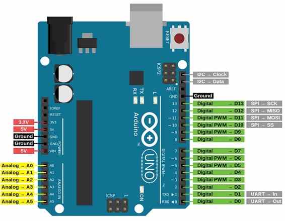
Hardware Setup Diagram

Pin diagram of Arduino uno
LED blinking Program
int LEDpin = 13;
//Declare an integer variable 'LEDpin' and set it to 13, which represents the pin number connected to the LED.

int delayT = 1000;
//Declare an integer variable 'delayT' and set it to 1000, which represents the delay time in milliseconds (1 second).

void setup() {
    //The setup function runs once when the microcontroller is powered on or reset.
    pinMode(LEDpin, OUTPUT);
    //Set the pin mode of 'LEDpin' (pin 13) to OUTPUT, indicating that it will be used to send signals to the LED.
}

void loop() {
    //The loop function runs continuously after the setup function, creating an infinite loop.
    digitalWrite(LEDpin, HIGH);
    //Set the digital output of pin 13 to HIGH (turn the LED on).
    delay(delayT);
    //Wait for the duration specified in 'delayT' (1000 milliseconds or 1 second).
    digitalWrite(LEDpin, LOW);
    //Set the digital output of pin 13 to LOW (turn the LED off).
    delay(delayT);
    //Wait for the duration specified in 'delayT' (1000 milliseconds or 1 second) before repeating the loop.
}
Simulated using https://www.tinkercad.com/

After compiling the code a, upload to arduino with correct port no
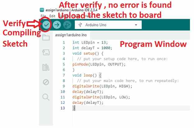
After Uploading the Code
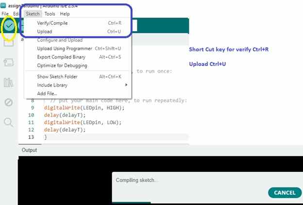
2. ESP32-WROOM-32E
Use the same Arduino IDE setup and installed the ESP32 board package for communicating with the board.
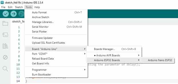
After installing library select the port and board, for suitable communication with the ports
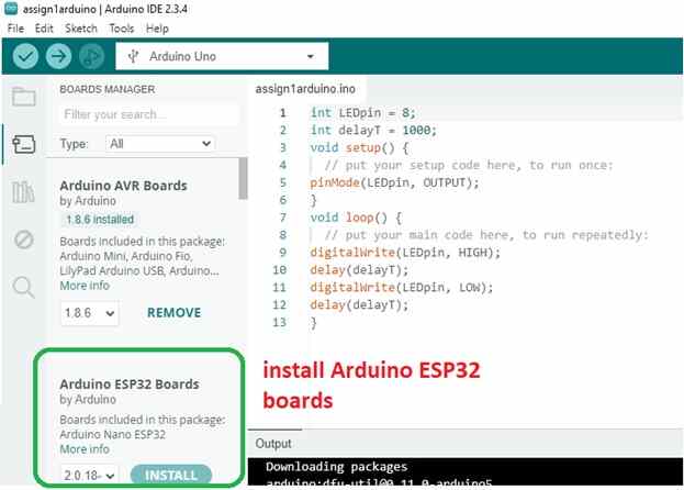
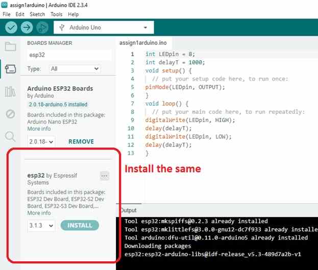
I am unable to perform the operations.So I followed the steps in the link https://randomnerdtutorials.com/installing-the-esp32-board-in-arduino-ide-windows-instructions/
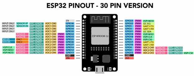
Connect the ESP32-WROOM-32E via USB. I have used the Pin diagram of ESP32
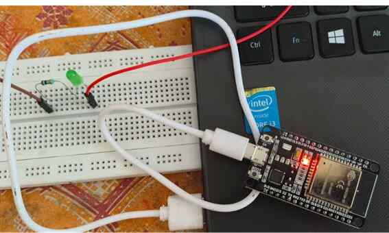
The following prgram is uploaded in the ESP 32
#define LED 2

void setup() {
  // Set pin mode
  pinMode(LED, OUTPUT);
}

void loop() {
  delay(50); // you can set the delay time by adjusting the parameter of delay();
  digitalWrite(LED, HIGH);
  delay(50);
  digitalWrite(LED, LOW);
}
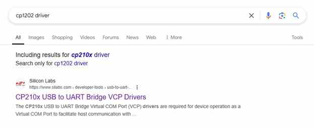
After Installing this driver in my windows I am unable to communicate to ESP Dev32 module
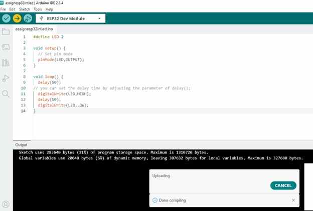
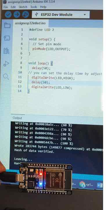
Program is transferred over COM10 Port to ESP Dev32 Module
XIAO RP2040
Using the Same Arduino IDE. I had installed the RP2040 board package
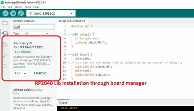
Select the board and port for the XIAO RP 2040
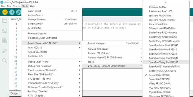
Connect the XIAO RP2040 via USB for uploading the program
I have used the below pin diagram of XIAORP2040 for my reference for connecting LED
Writing the code through Arduino IDE
// the setup function runs once when you press reset or power the board
void setup() {
  // initialize digital pin LED_BUILTIN as an output.
  pinMode(LED_BUILTIN, OUTPUT);
}

// the loop function runs over and over again forever
void loop() {
  digitalWrite(LED_BUILTIN, HIGH); // turn the LED on (HIGH is the voltage level)
  delay(1000); // wait for a second
  digitalWrite(LED_BUILTIN, LOW); // turn the LED
}
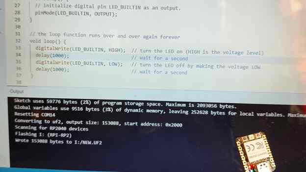
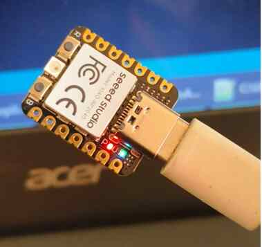
XIAO ESP32C3
1.Using the Same Arduino IDE and Esp32 packages is already added and now i need to select the board and port for communication
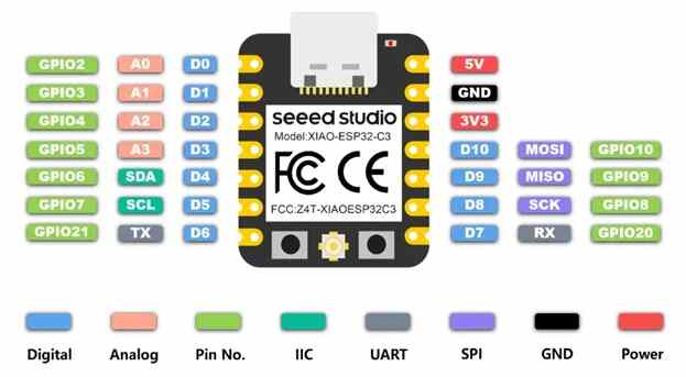
Pin diagram of XIAO ESP32c3
Simple LED Program with push button
LED Anode is connected to ESP32c3 pin 2 and another terminal connected to GnD
Push button is connected to ESP32c3 pin 3 and another terminal connected to GnD
#define LED_PIN 2 // LED connected to Pin 2
#define BUTTON_PIN 3  // Push button connected to pin 3

bool ledState = false;

void setup() {
    pinMode(LED_PIN, OUTPUT);
    pinMode(BUTTON_PIN, INPUT_PULLUP); // Use internal pull-up resistor
}

void loop() {
    if (digitalRead(BUTTON_PIN) == LOW) {  // Button pressed (LOW due to pull-up)
        delay(200);  // Debounce delay
        ledState = !ledState;  // Toggle LED state
        digitalWrite(LED_PIN, ledState);
        while (digitalRead(BUTTON_PIN) == LOW); // Wait until button is released
    }
}
XIAO ESP32C3 -LED Control Using Wifi in Window Screen
Selected the board and port for the XIAO ESP32C3
Simple LED Program with Wifi Control
This program is designed for an ESP32-based board (like the XIAO ESP32) and uses WiFi connectivity to allow remote control of an LED via a simple web interface. Below is an explanation of how the code works:
#includeThis includes the WiFi.h library, which allows the ESP32 to connect to a WiFi network and serve web pages. Global Variables: cpp Copy const char* ssid = "sujith"; const char* password = "123456878"; ssid and password store the WiFi network credentials that the ESP32 will use to connect to a WiFi network. cpp Copy WiFiServer server(80); This line creates a WiFiServer object that listens on port 80 (default HTTP port) for incoming client connections. cpp Copy int ledPin = D1; // GPIO2 (D2) on XIAO ESP32 ledPin specifies the pin (D1 in this case) to which the LED is connected. setup() Function: cpp Copy void setup() { pinMode(ledPin, OUTPUT); digitalWrite(ledPin, LOW); Serial.begin(115200); WiFi.begin(ssid, password); while (WiFi.status() != WL_CONNECTED) { delay(1000); Serial.println("Connecting to WiFi..."); } Serial.println("Connected to WiFi!"); Serial.print("IP Address: "); Serial.println(WiFi.localIP()); server.begin(); } Pin Setup: The ledPin is configured as an output, and initially, the LED is turned off (digitalWrite(ledPin, LOW)). Serial Monitor: The serial communication is initialized at 115200 baud rate for debugging output. WiFi Connection: The ESP32 attempts to connect to the WiFi network using WiFi.begin(ssid, password). It keeps checking the connection status until it's connected, printing a message to the serial monitor every second. Once connected, the IP address assigned to the ESP32 by the router is printed to the serial monitor. Start Web Server: The web server is started using server.begin() to begin listening for incoming client requests. loop() Function: cpp Copy void loop() { WiFiClient client = server.available(); if (client) { String request = client.readStringUntil('\r'); client.flush(); Wait for Client: The server checks if there is any client trying to connect. If a client is available, it reads the request sent by the client. Request Parsing: The request is read until a carriage return (\r) is received, and the flush() function ensures that any leftover data in the input buffer is discarded. cpp Copy if (request.indexOf("/LED=ON") != -1) { digitalWrite(ledPin, HIGH); } else if (request.indexOf("/LED=OFF") != -1) { digitalWrite(ledPin, LOW); } Control LED: Based on the client's request, the program checks if the URL contains /LED=ON or /LED=OFF. If /LED=ON is part of the request, the LED is turned on (digitalWrite(ledPin, HIGH)). If /LED=OFF is part of the request, the LED is turned off (digitalWrite(ledPin, LOW)). cpp Copy client.println("HTTP/1.1 200 OK"); client.println("Content-type:text/html"); client.println(); client.println(""); client.println(" XIAO ESP32 LED Control
"); client.println(""); client.println(""); client.println(""); client.println(); } } HTTP Response: After processing the request, the ESP32 sends back an HTTP response to the client: The status code 200 OK is sent to indicate a successful request. The content type is set to text/html, meaning the response will be an HTML page. HTML Content: The server generates a simple web page with: A heading: "XIAO ESP32 LED Control." Two buttons, one for turning the LED on (/LED=ON) and one for turning it off (/LED=OFF). Sending the Response: The HTML page is sent to the client, and after the page is displayed, the connection is closed automatically.
Python Programming in XIAO RP2040
Circuit Python
To use CircuitPython, I needed the CircuitPython firmware for the XIAO RP2040:I visited the CircuitPython Downloads page.There, I searched for "XIAO RP2040" and downloaded the latest UF2 file.Next, I put the XIAO RP2040 into bootloader mode by double-pressing the reset button. The board appeared as a USB drive named "RPI-RP2."I dragged and dropped the UF2 file onto this drive. Instantly, the board rebooted and appeared as a new drive named "CIRCUITPY."Once the board was ready, I opened a text editor (I used Mu Editor, which is CircuitPython-friendly). I made sure Mu was set to CircuitPython mode and connected it to my XIAO RP2040.
I followed the steps in the link https://wiki.seeedstudio.com/XIAO-RP2040-with-CircuitPython/


Finally i have uploaded the following program for blinking led. it was running on first time. Its my success on the board
import time
import board
import digitalio

led = digitalio.DigitalInOut(board.LED)
led.direction = digitalio.Direction.OUTPUT

while True:
    led.value = True  # Turn the LED ON
    time.sleep(0.5)   # Wait for 0.5 seconds
    led.value = False  # Turn the LED OFF
    time.sleep(0.5)   # Wait for 0.5 seconds
Circuit Python
I followed the steps in the link https://wiki.seeedstudio.com/XIAO-RP2040-with-MicroPython/
Below steps i have followed for my execution


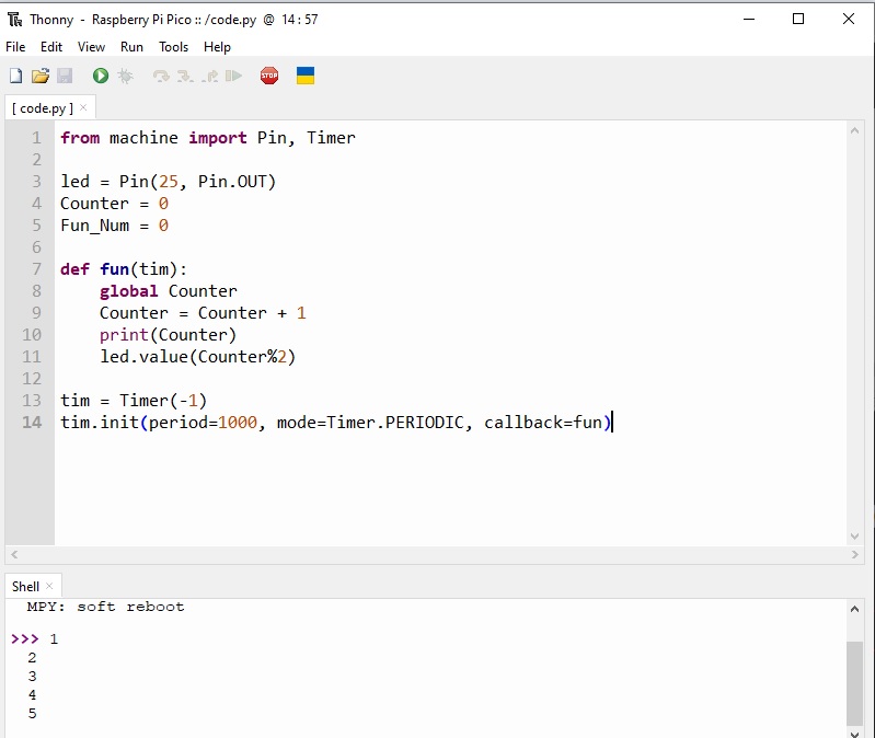
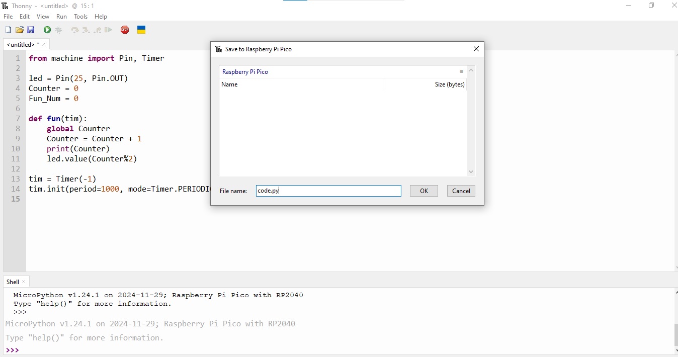
Finally i have uploaded the following program for blinking led. it was running on first time. without any problem i have uploaded and run the code
from machine import Pin, Timer

led = Pin(25, Pin.OUT)
Counter = 0
Fun_Num = 0

def fun(tim):
    global Counter
    Counter = Counter + 1
    print(Counter)
    led.value(Counter%2)

tim = Timer(-1)
tim.init(period=1000, mode=Timer.PERIODIC, callback=fun)
Hero Shots

All Proramming File
Download source codeProblems faced and learned
-I m facing problem with adding libraries and connection ports for xiao model in Arduino IDE, After that installed the interface for communication CP210x USB to UART Bridge VCP Drivers
Learned in this week
😀 Learned to understand All development boards like arduino, esp32, xiao rp2040, xiao esp32c3 😀
😀 Learned to how to install the libraries, way to find another libraries in github😀
😀 Learned to use communication models wifi, bluetooth and familar with some part of coding 😀
Happy Learning
😀 Suith Mayakrishnan 😀