review the safety data sheets for each of your molding and casting materials, then make and compare test casts with each of them compare mold making processes
Individual Assignment
Design a mold around the process you'll be using, produce it with a smooth surface finish that does not show the production process toolpath, and use it to cast parts
This week is entirely new for me in molding and casting, and I'm excited to learn new things. However, I'm still struggling with 3D modeling because of non mechanical background beginner in 3d modelling. Thankfully, with the instructor's guidance, I'm slowly understanding and improving my skills.
This week, I'll be working on molding and casting. Instead of designing a butterfly from scratch, I'll export a butterfly image and use it to create the mold. First, I'll generate a negative mold from this image, then 3D print the mold cavity. After that, I'll prepare the casting material, pour it into the mold, and produce a positive cast from the negative mold.
I find this definition in chatgpt
Molding/Moldmaking involves creating a cavity that contains a negative impression of an original model. The mold material can be rigid (like plaster or resin) or flexible (such as rubber), depending on factors like the model's material, casting requirements, and the presence of undercuts.
Casting is the process of pouring liquid material (like metal, epoxy, plaster, or clay) into the mold cavity. The material then solidifies—either through cooling or a chemical reaction—forming a replica of the original model. Once cured, the casting is removed from the mold to complete the process.
I used this website for reference https://www.3erp.com/blog/casting/
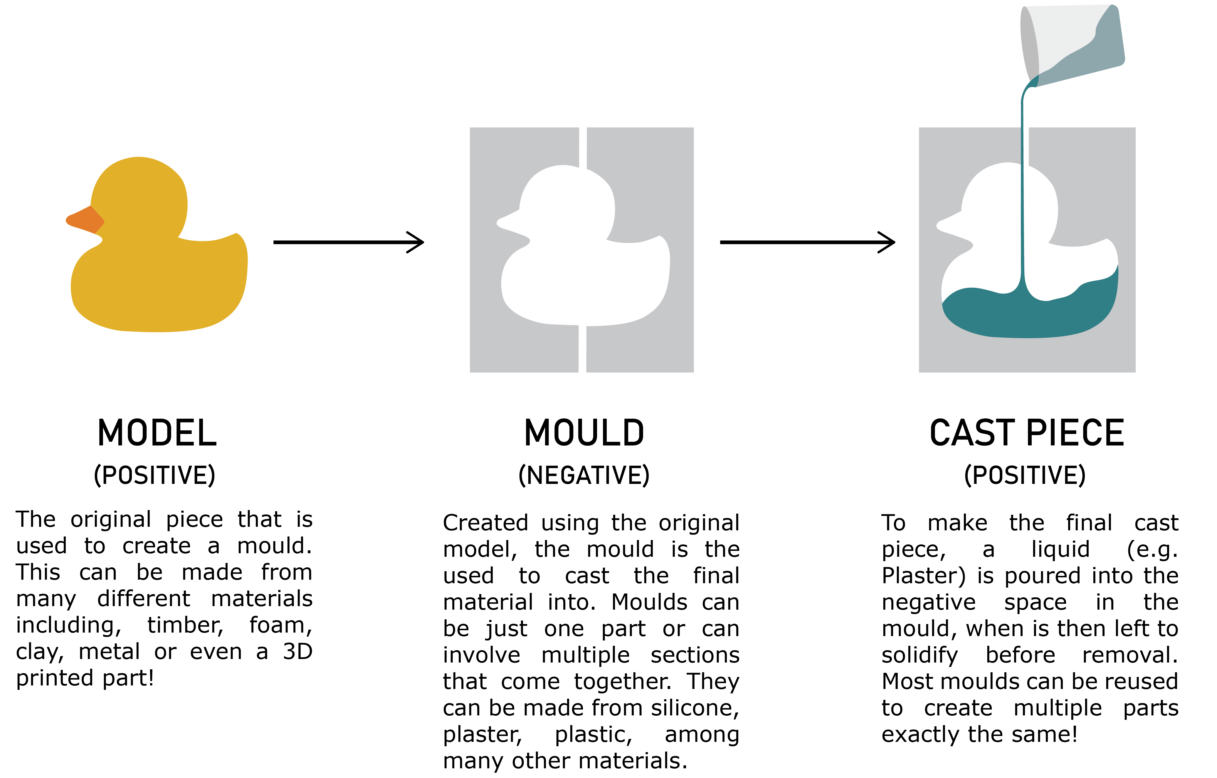
To understand the Casting process I have refered the https://www.making.unsw.edu.au/learn/casting_moulding_basics/ the image taken from this website
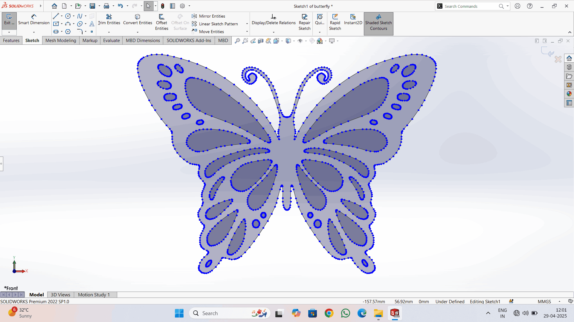
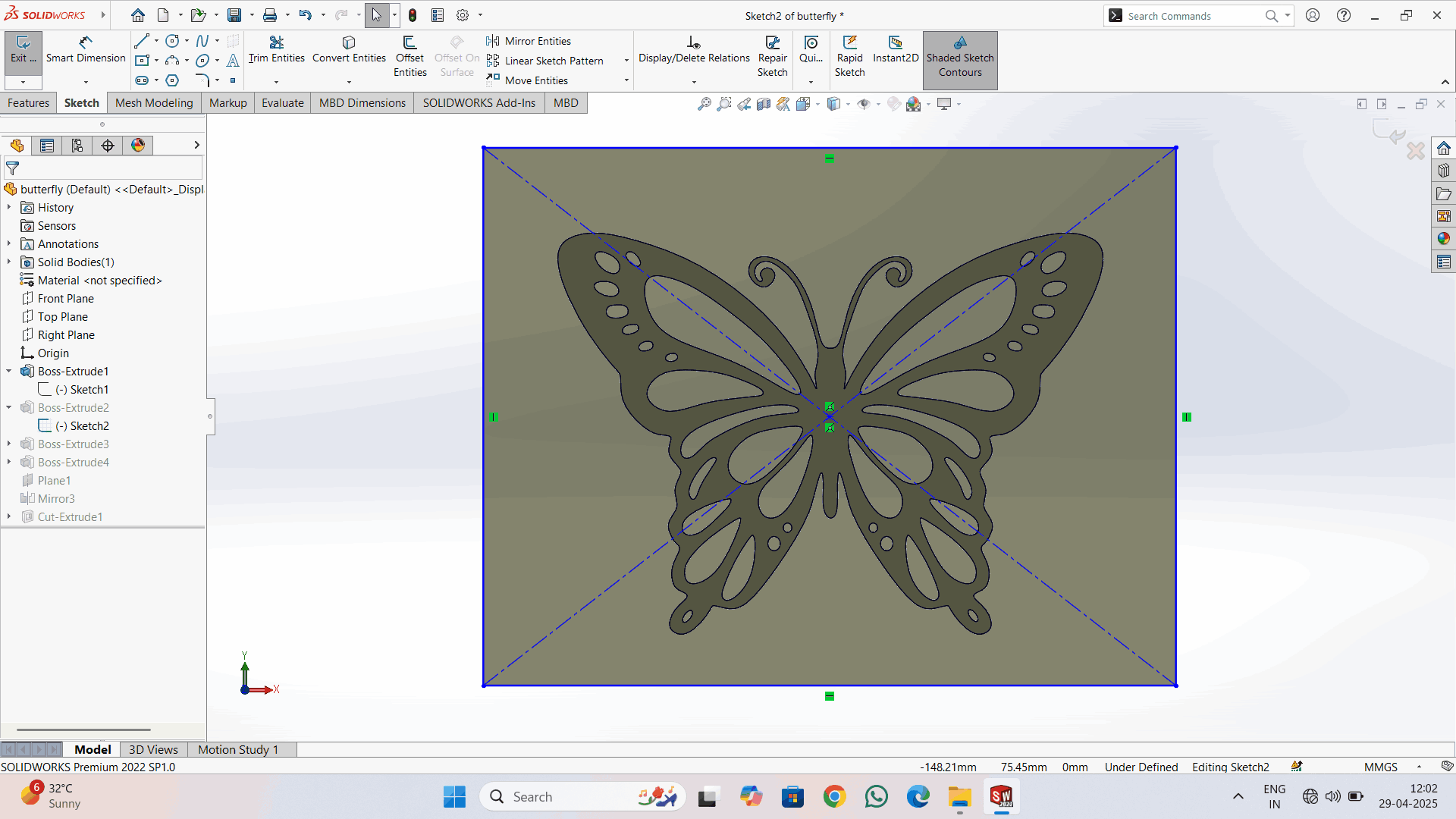
I have downloaded the butteryfly image and exported in to the solidworks and selected the option of sahded sketch contours
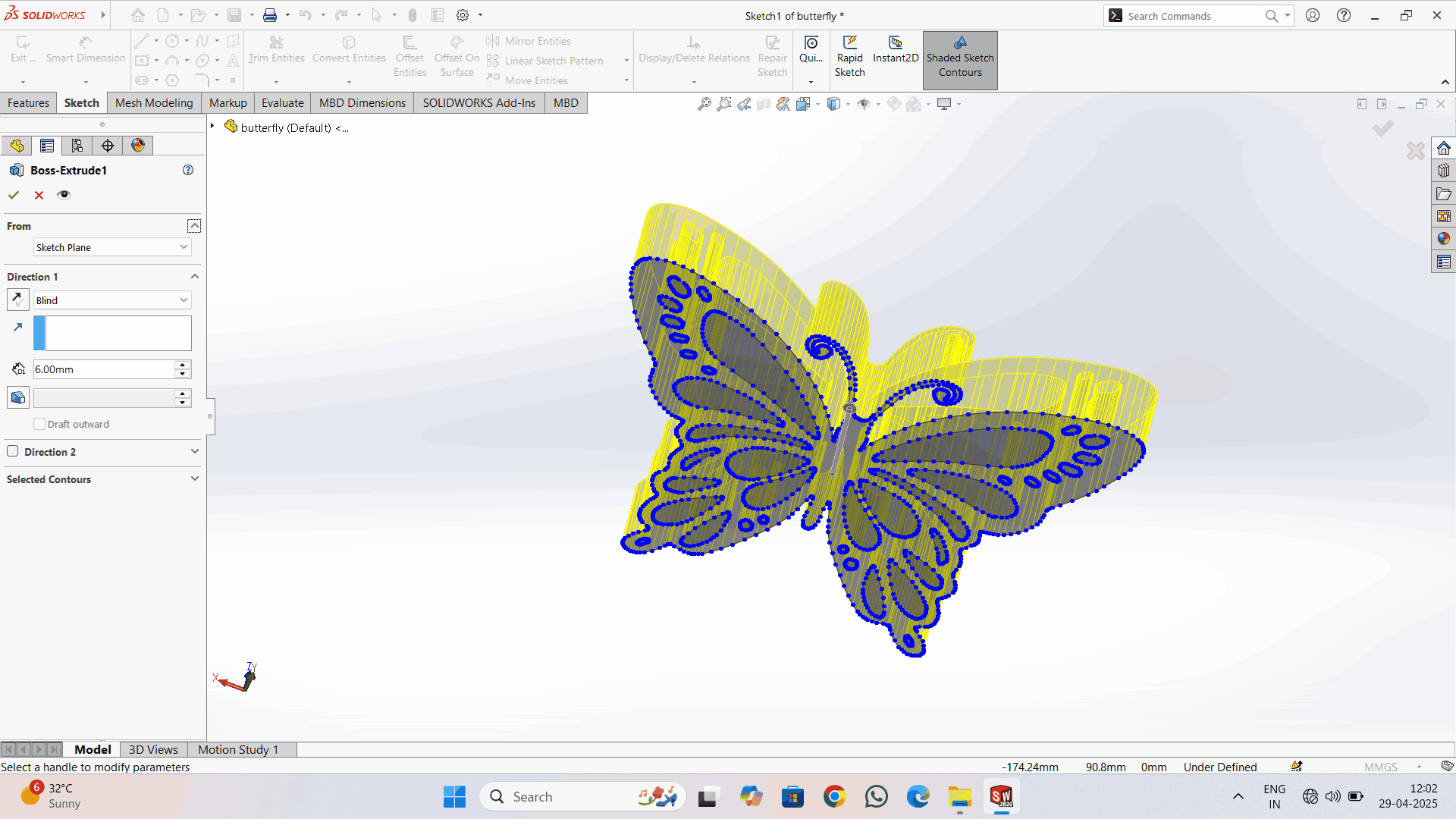
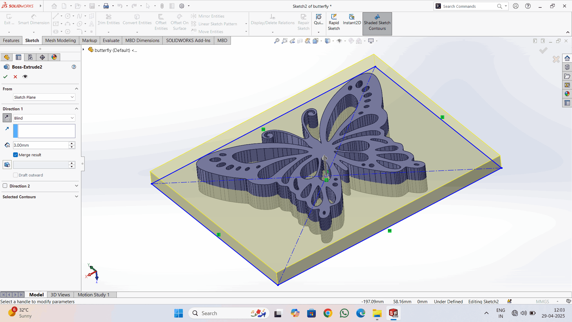
Next selecte the sketch option and boss -extrude and increased to 6mm width of the butterfly
I made the outer box
Extrude the box by 3mm
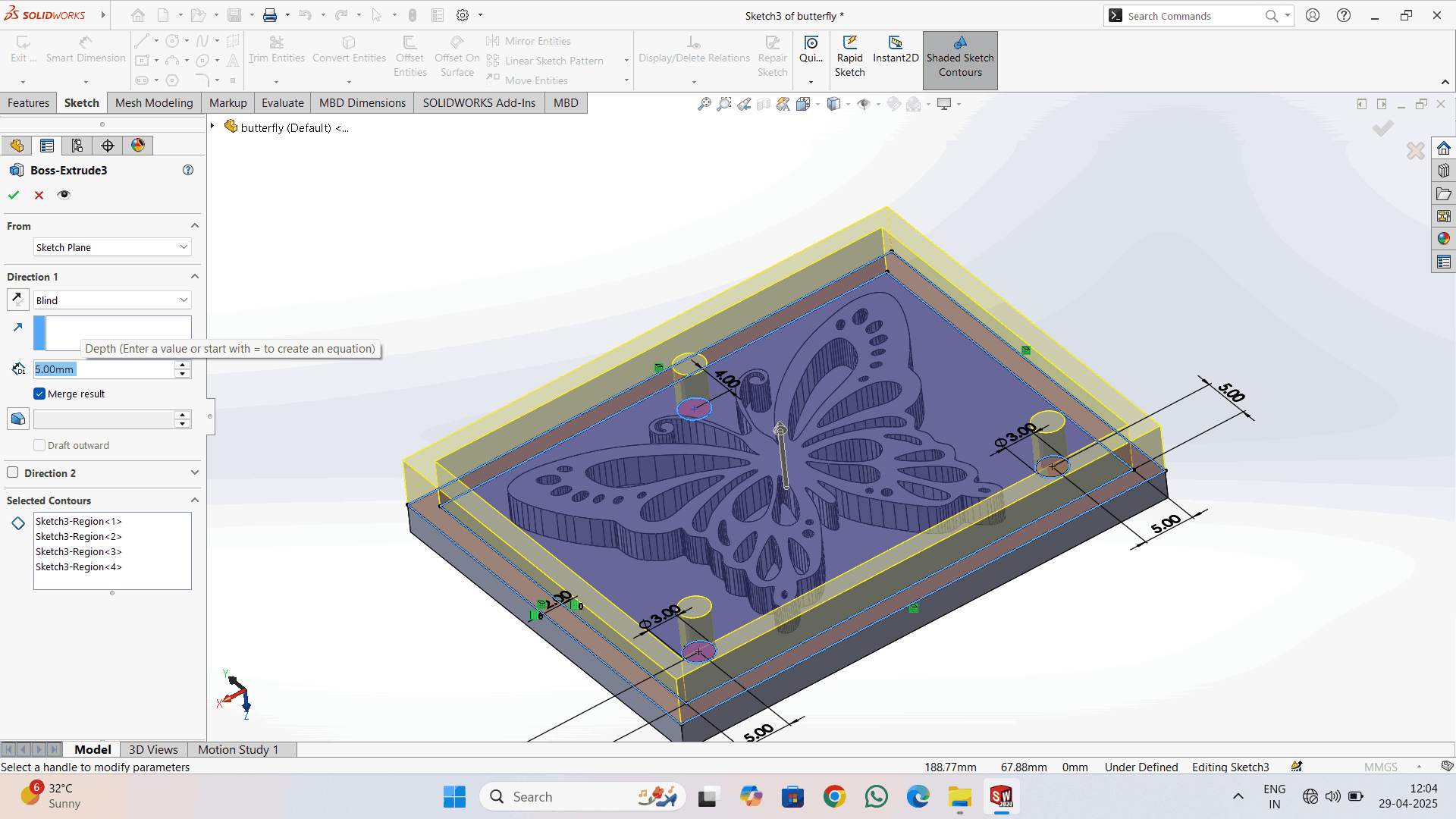
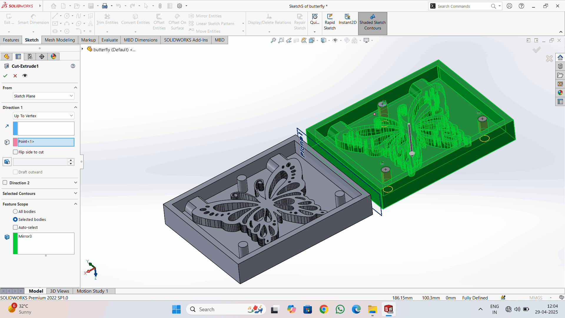
Then I made three circles on the given face and extruded them up to the top surface. I also applied a taper angle of 5 degrees and 3mm dia for easy removal and insertion of the two parts.
Then I created a plane by selecting reference > plane > selecting the surface or side > coinciding with that.
I used Mirror command to mirror the Bodies using above reference plane.
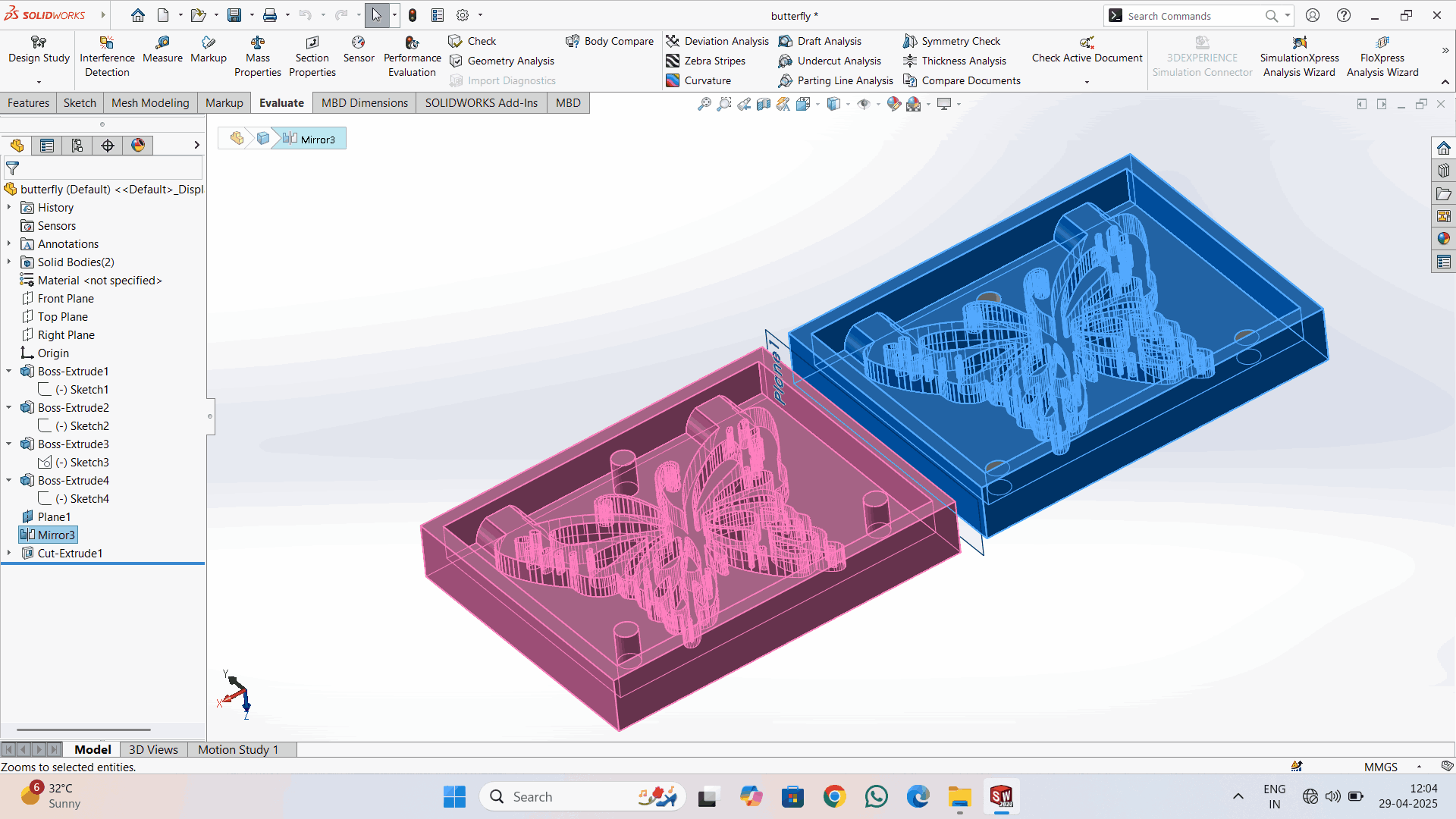
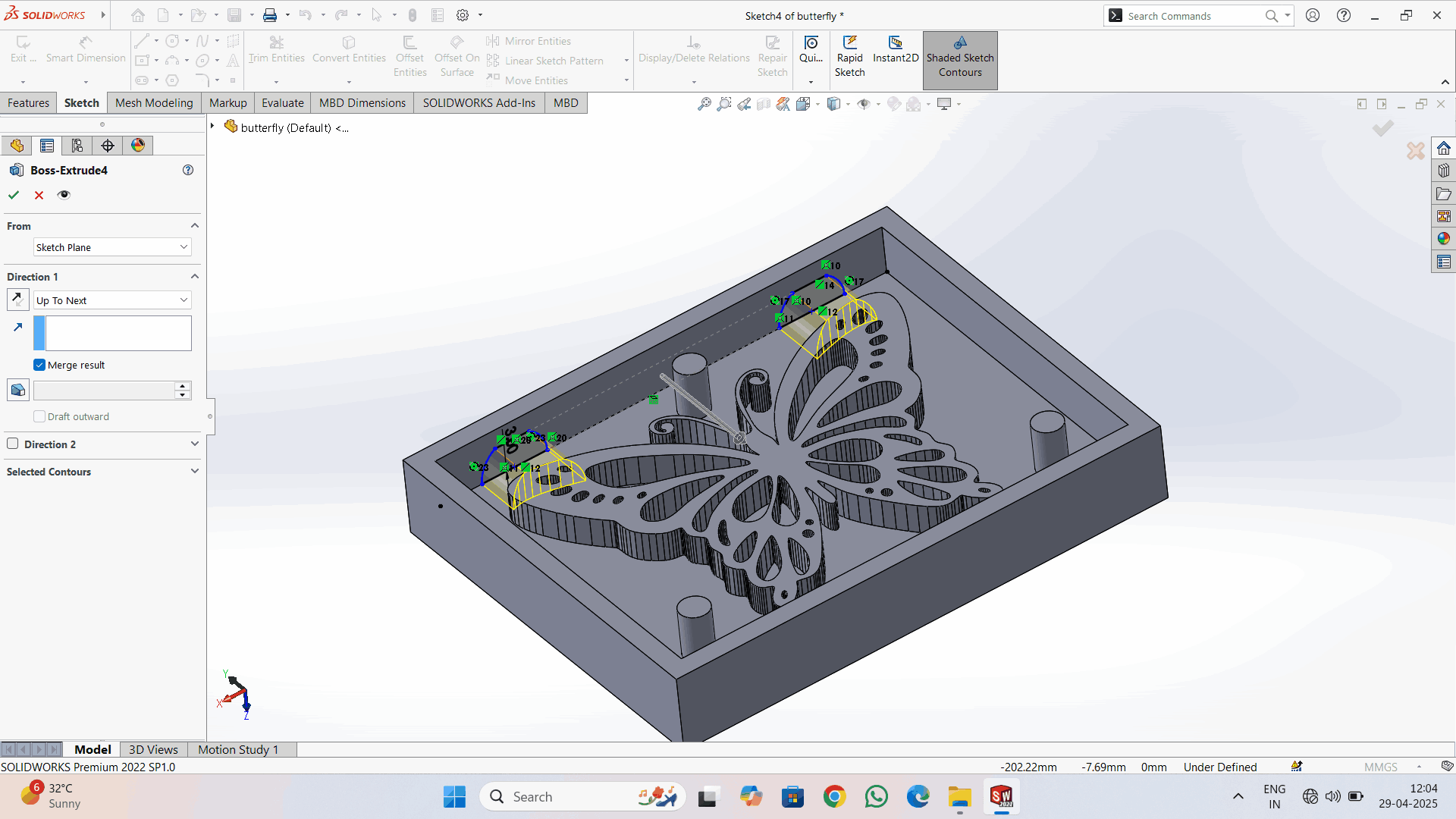
Then I created the holes on the mirrored side and also applied a taper angle of 5 degrees.
After creating the negative mould, checked on 3D Instant on solid works
backside of the plane / box seen in 3D
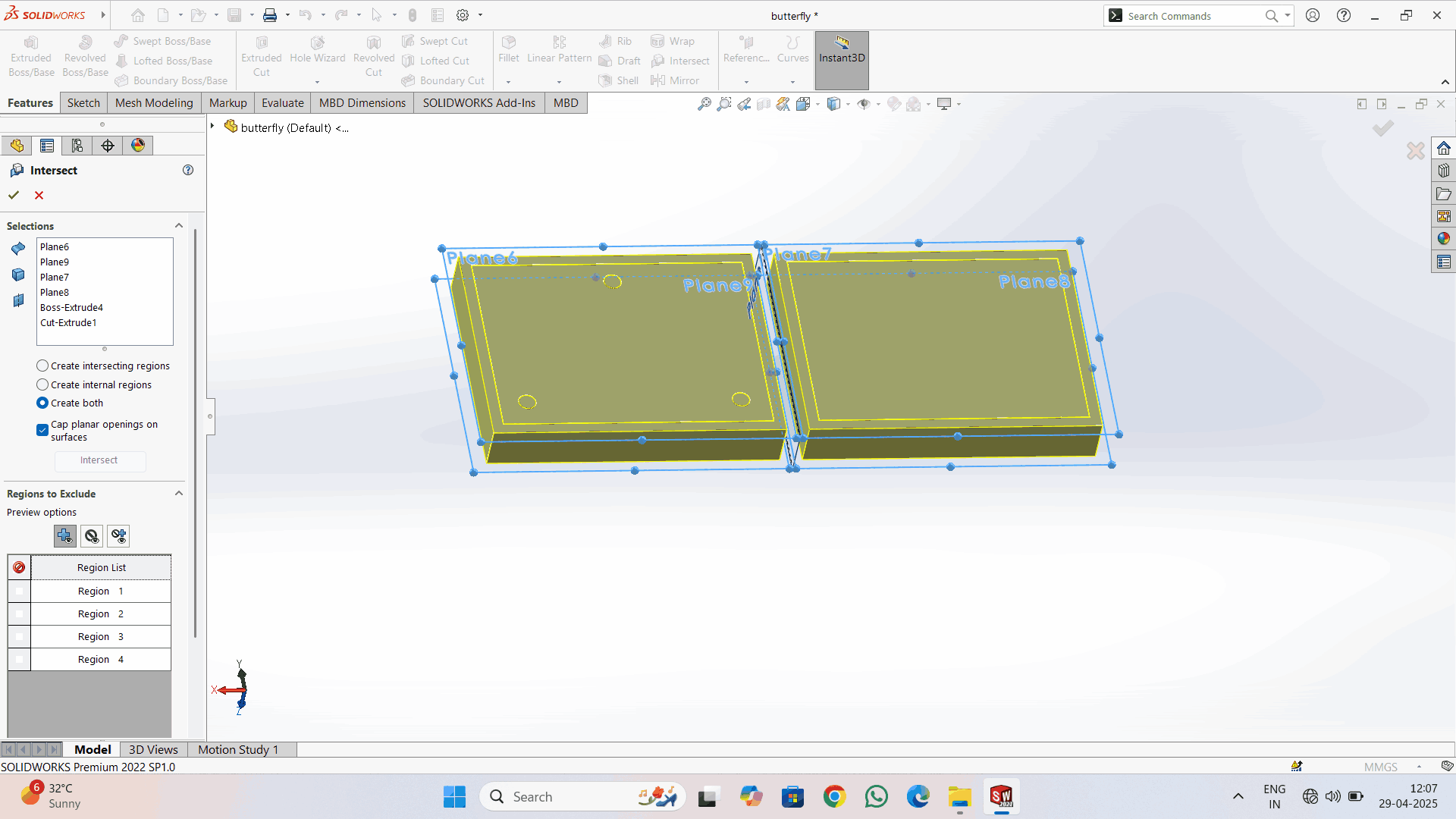
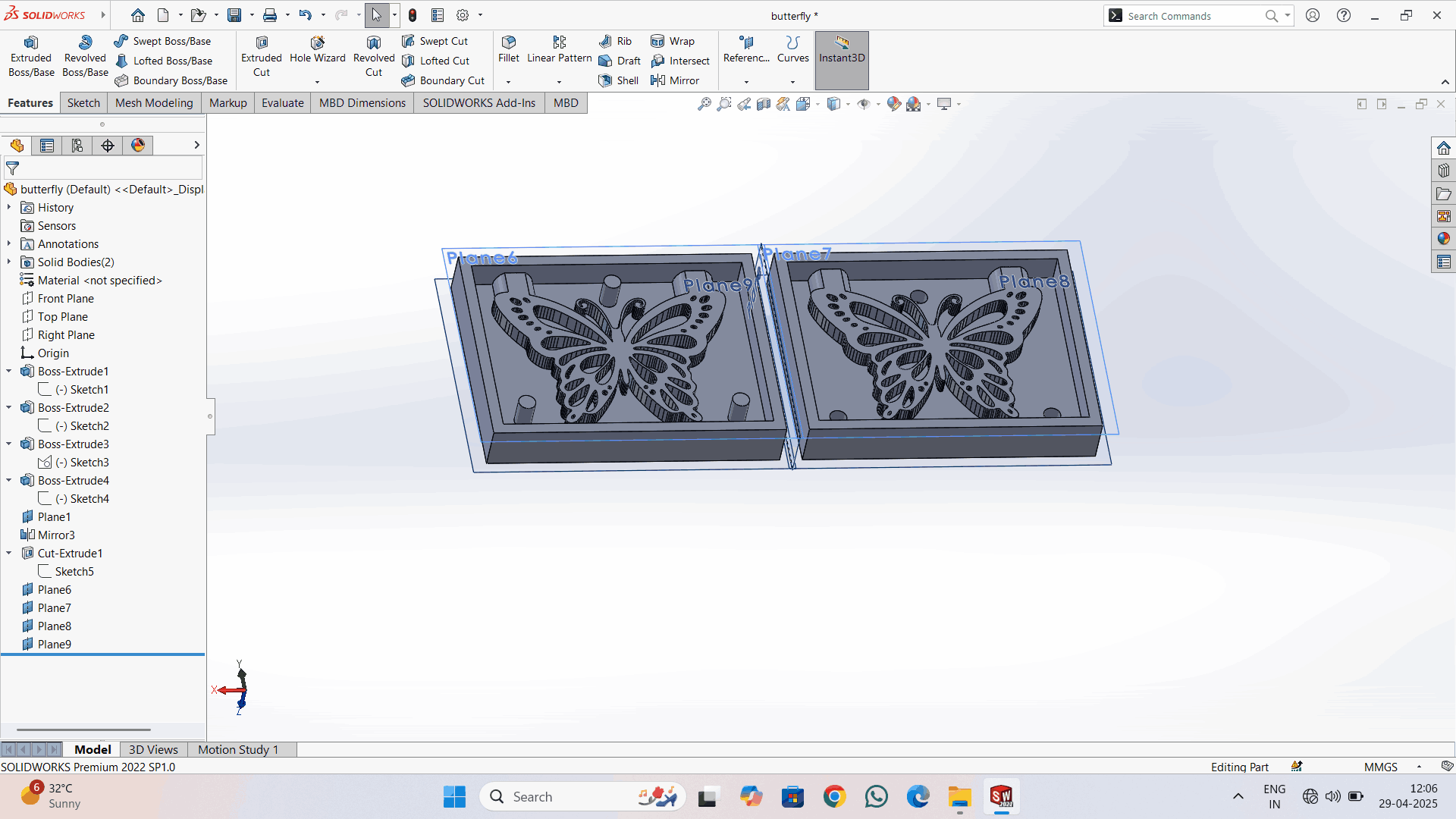
Click on Insert > Features > Intersect
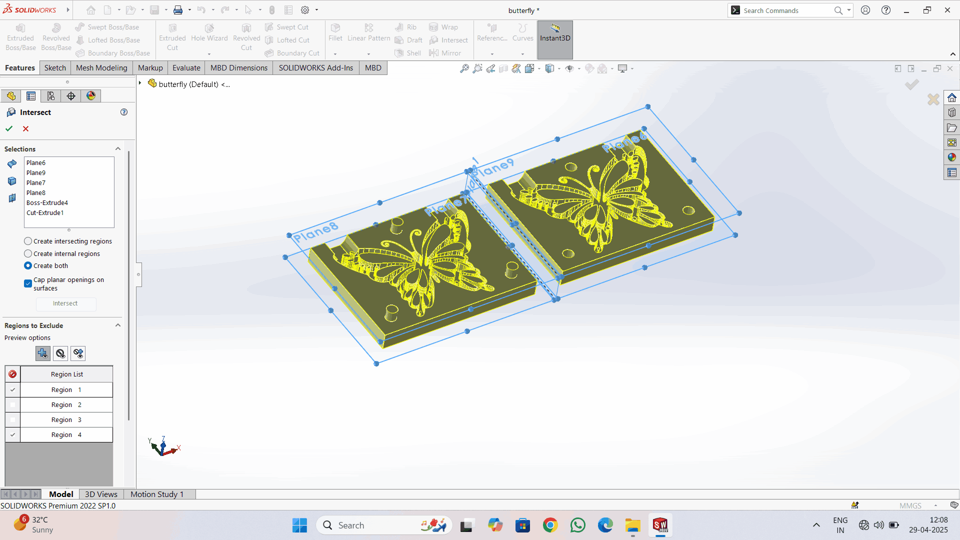
For calculating the mass of the material that we're going to pour into it, I used the intersect option in SolidWorks. I made two planes to cover all the body.
Navigate to Evaluate > Mass Properties For calculating the mass of that part.
Click on Options > Use Custom Settings > enter the Density of substance that i want to pour into the Mould Cavity.
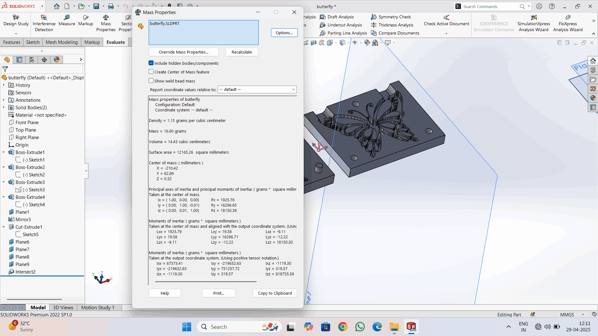
from above image I calculated the Mass : 16.60 grams and the Volume : 14.43 cc.
I am using any cubic slicer model
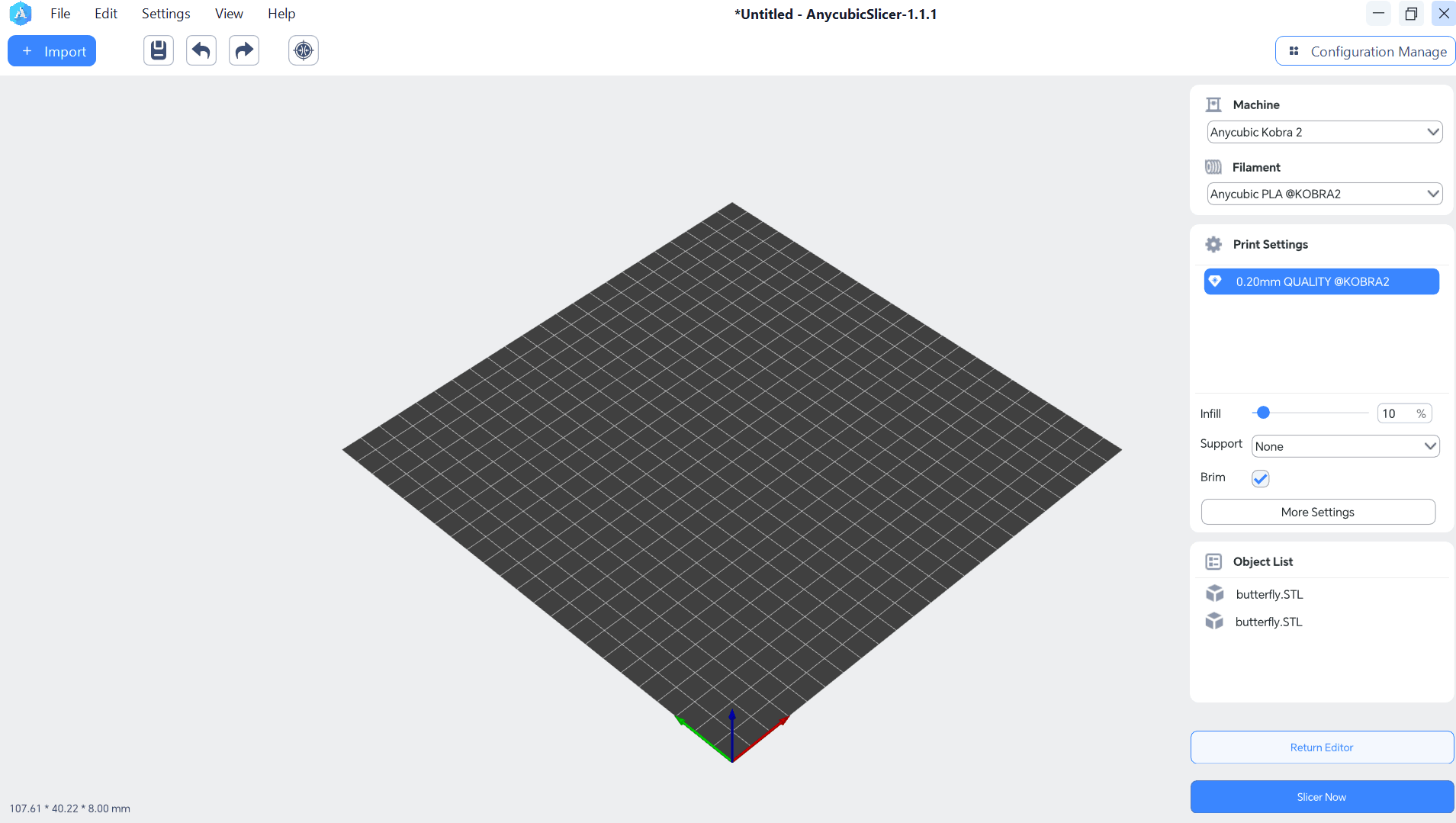
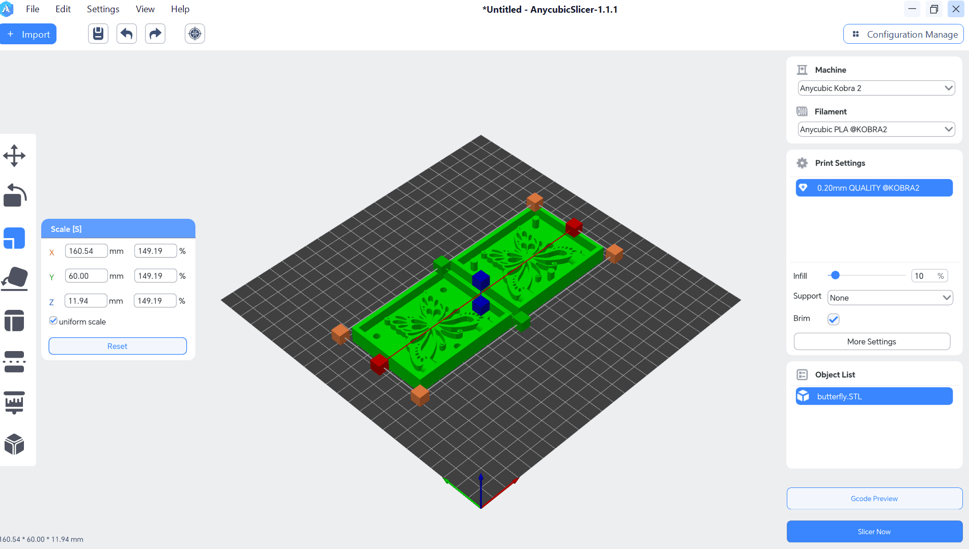
Now Uploaded the created butterfly dxf file in to any cubic slizer in STL format
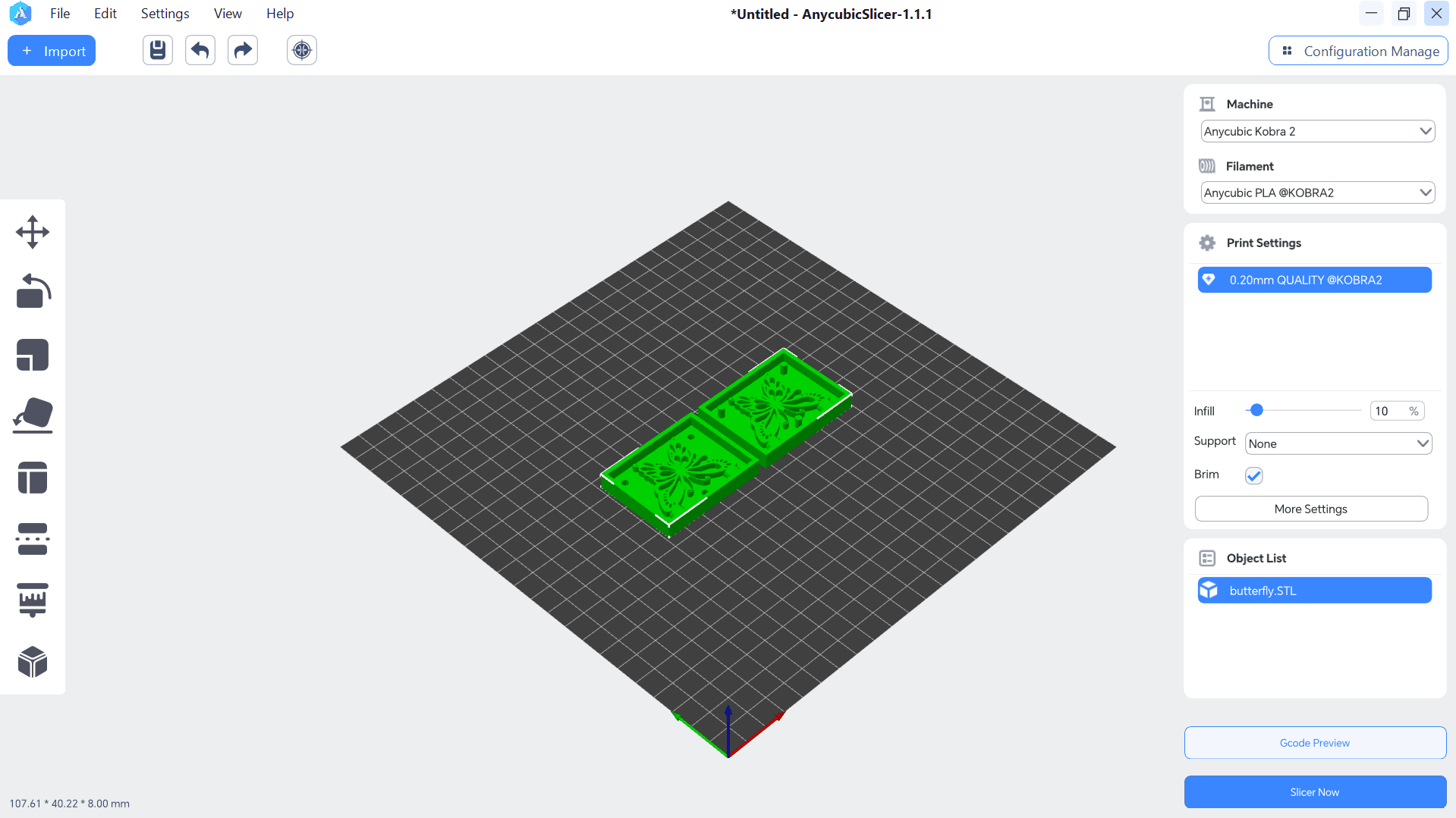
Now fixed the scale shown in fogure
Using features option, estimated printing time is 2hr 14m approxiately same time will be taken by any cubic printer , material i used is PLA for design printing
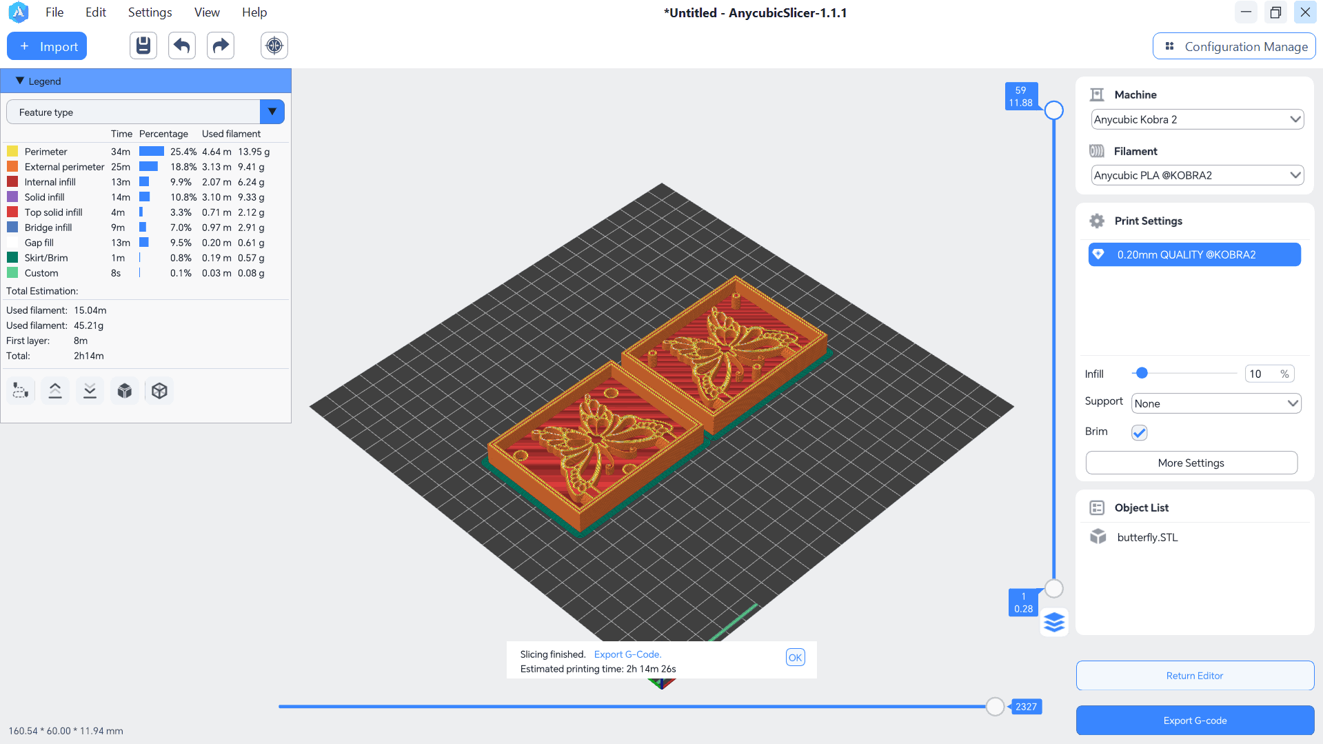
After conversion in to g code and uploaded the code to any cubic printer
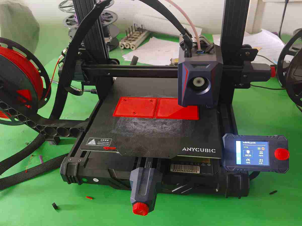
During the printing process
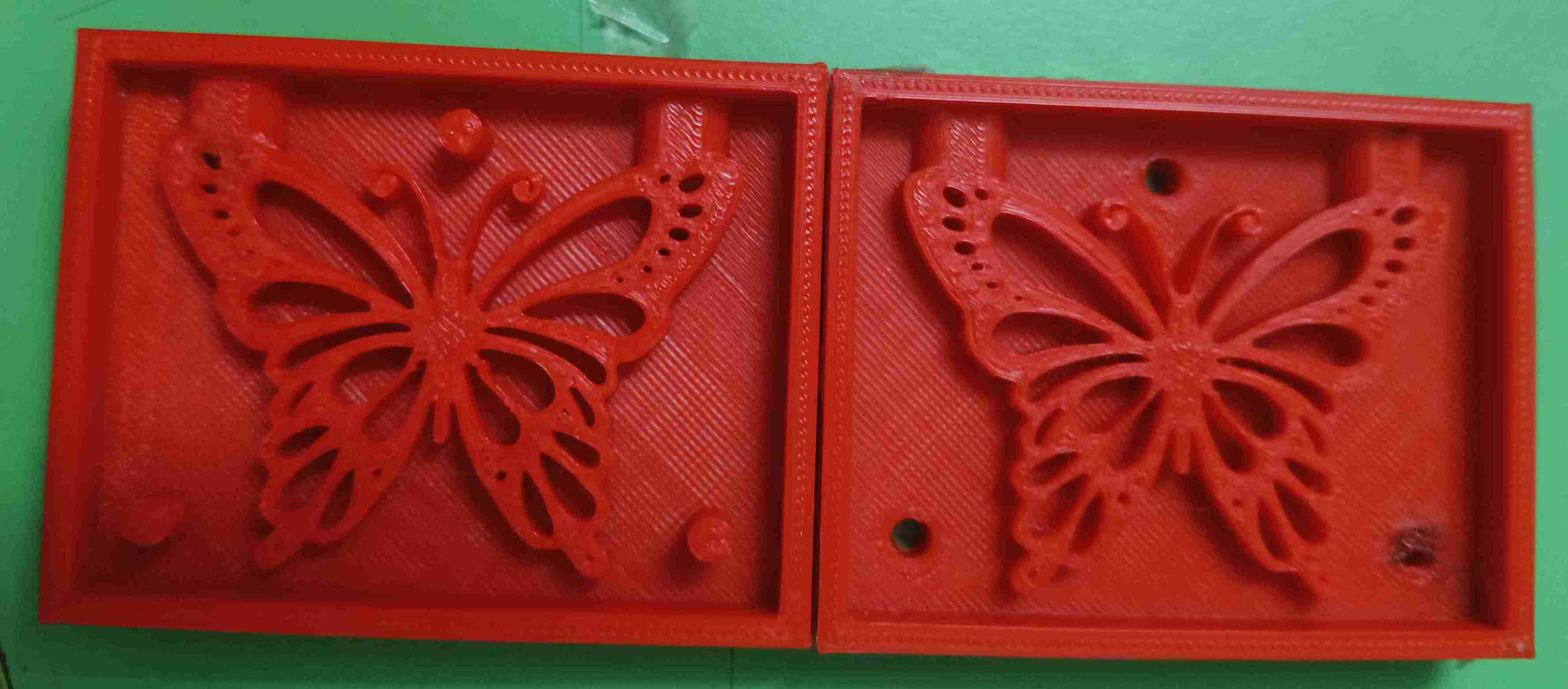
After completion of print , final output of the mould
After printing of negative mould, i used the ecoflex solution 00-50 , product information available in the website https://www.smooth-on.com/products/ecoflex-00-50/
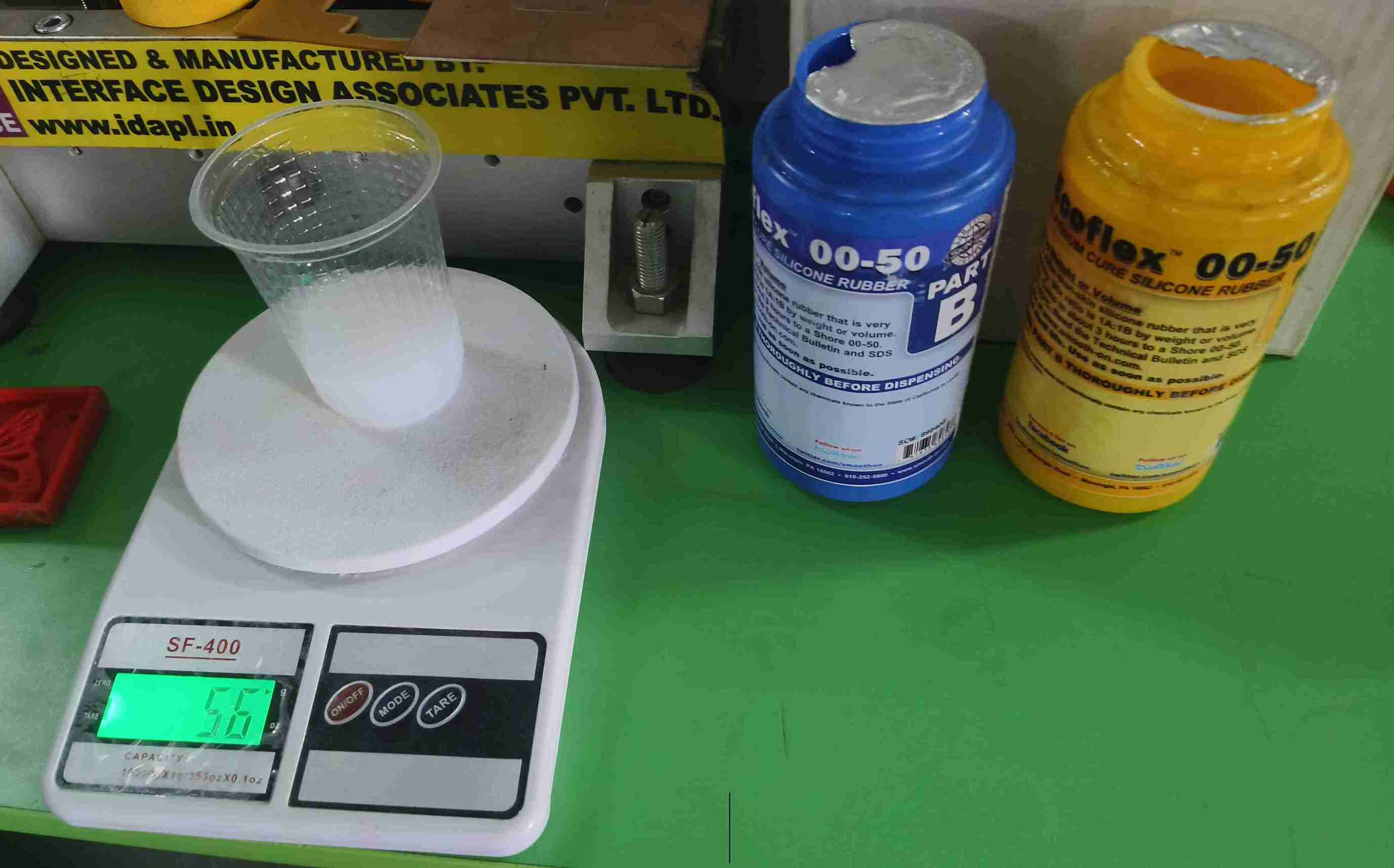
From Above picture, 00-50, it means Ecoflex™ rubbers are mixed 1A:1B Part A and PartB Solution is mixed in equal grams 28g (Part A) + 28g (Part B) mixed and measured using weighing machine
Poured the solution in created 3D mould, taken care to avoid bubbles
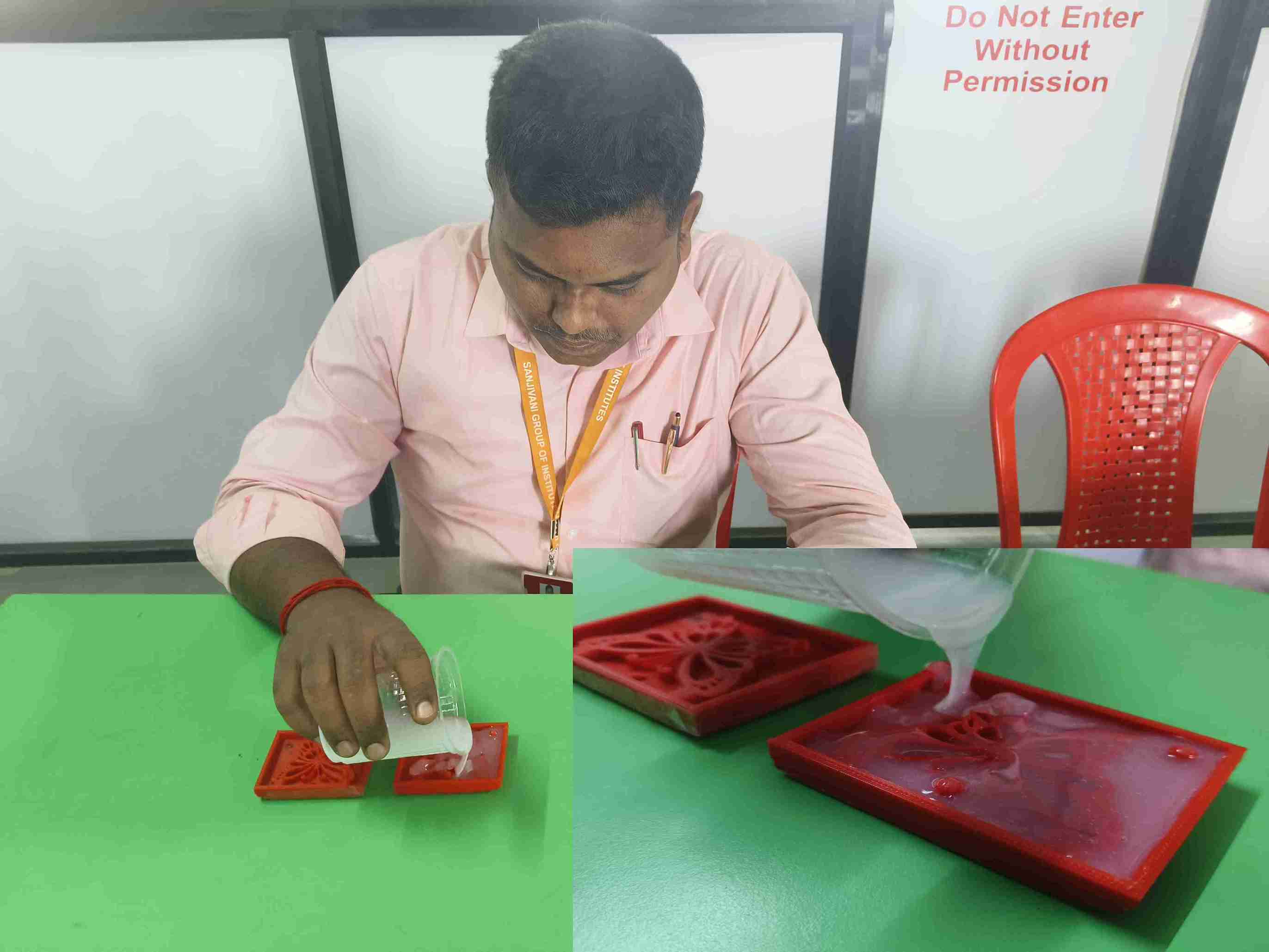
After filling the mixture, I removed all the bubbles from the mixture for the good quality of the mould, then after curing it for 24 hrs.
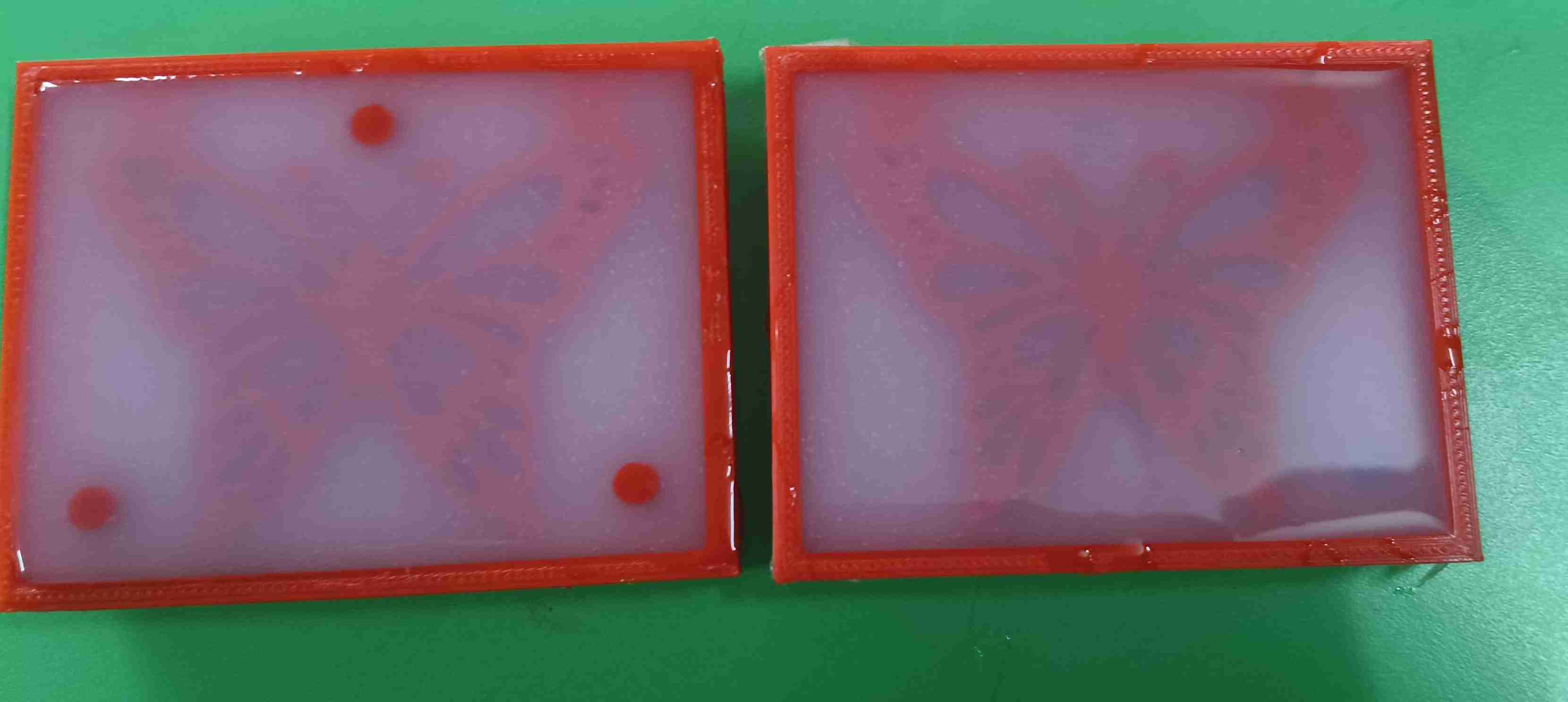
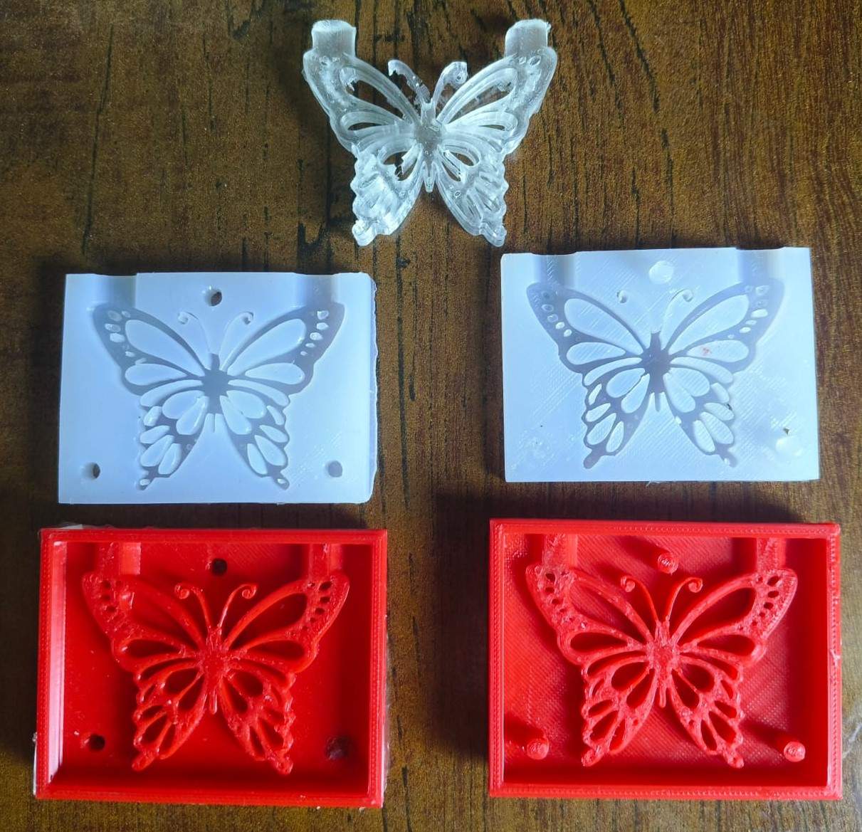
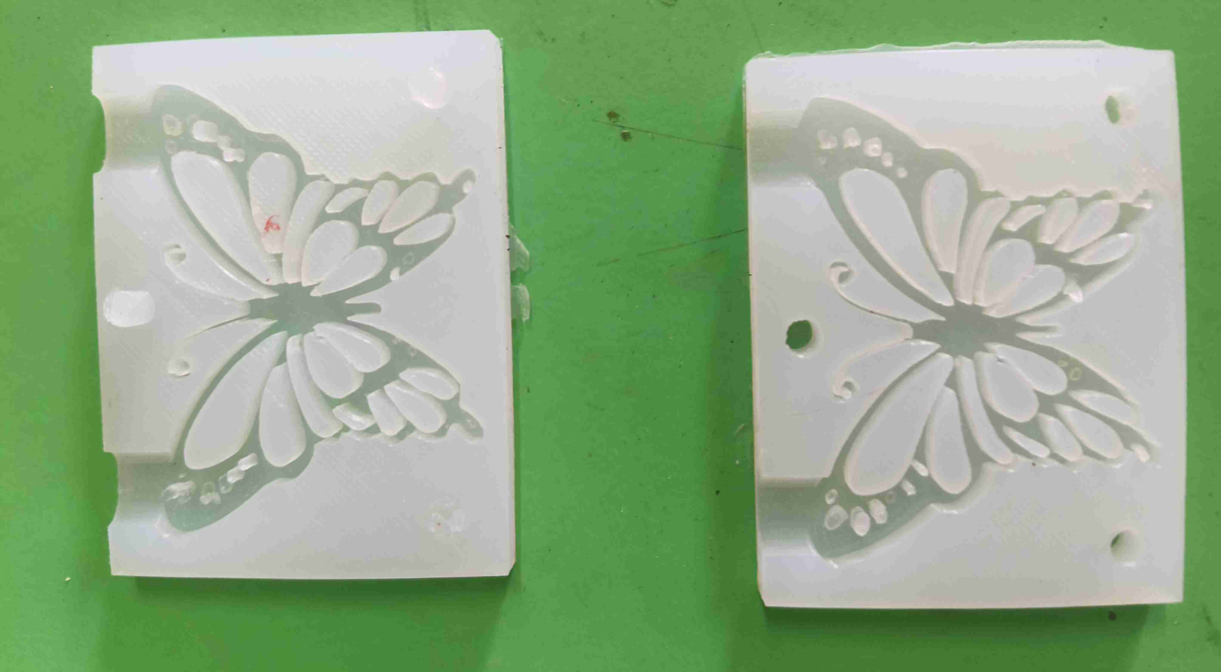
After that I removed the mould cavity from the 3d printed part, output of silicon rubber
Then i used the Epoxy resin for my final output, i mixed it in 1:2 ratio (Resin 20g + Hardener 10g = 10g), I covered the mould cavity using transperent tape and poured the epoxy resin into it also i added some shiny dust into it for glow
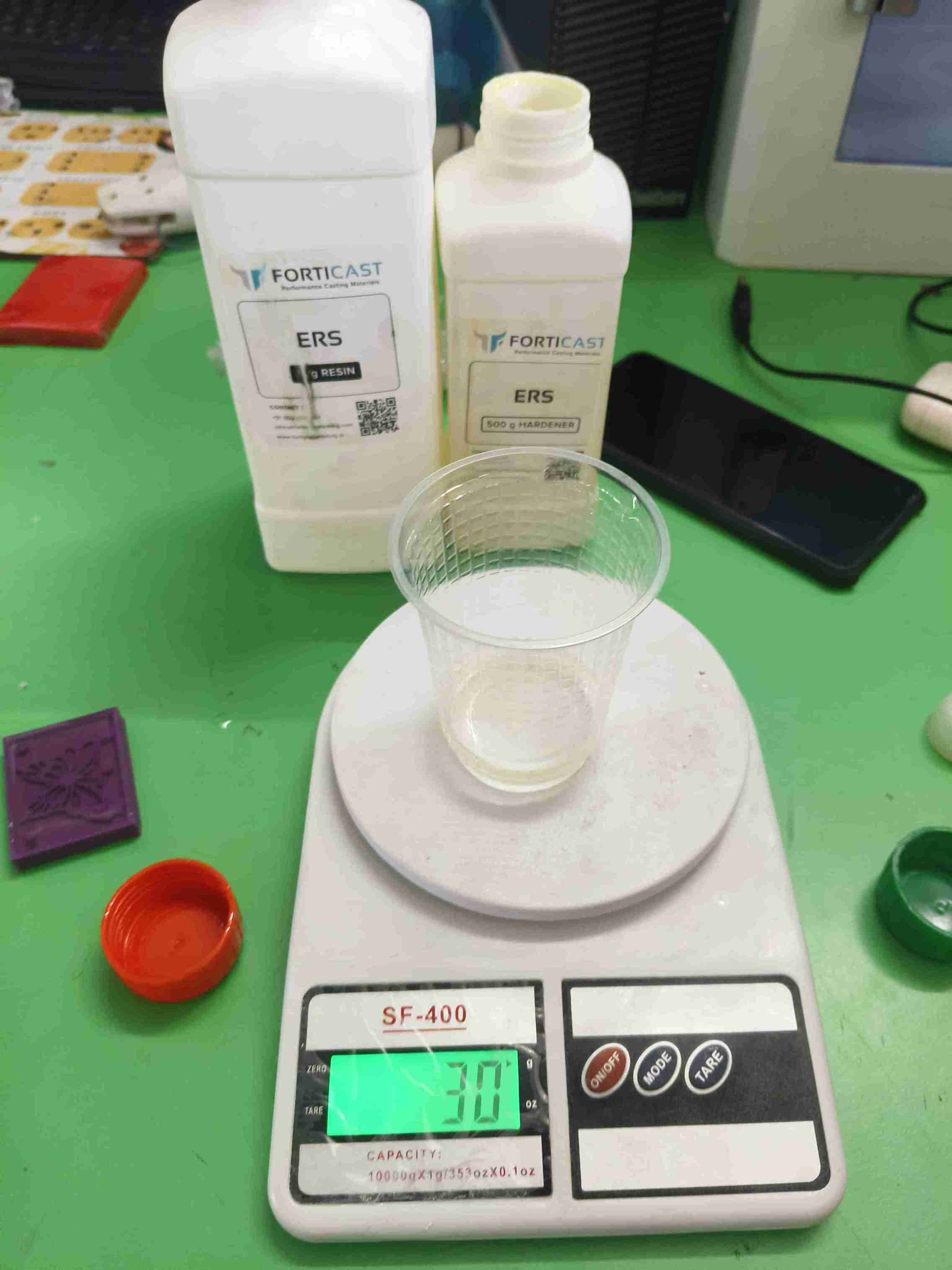
I used only 10g of the mixture for the casting (positive mould ), kept for 24 hrs curing period for the positive mould
After seperating negative mould, positive mould casting is created
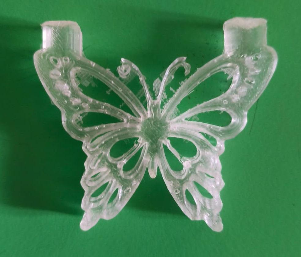
After Post Processing of the Casting , removed the extra layers, dust on the mould
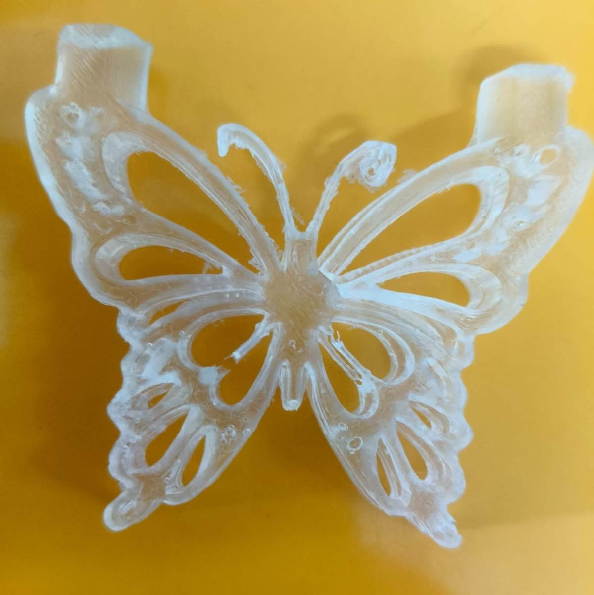
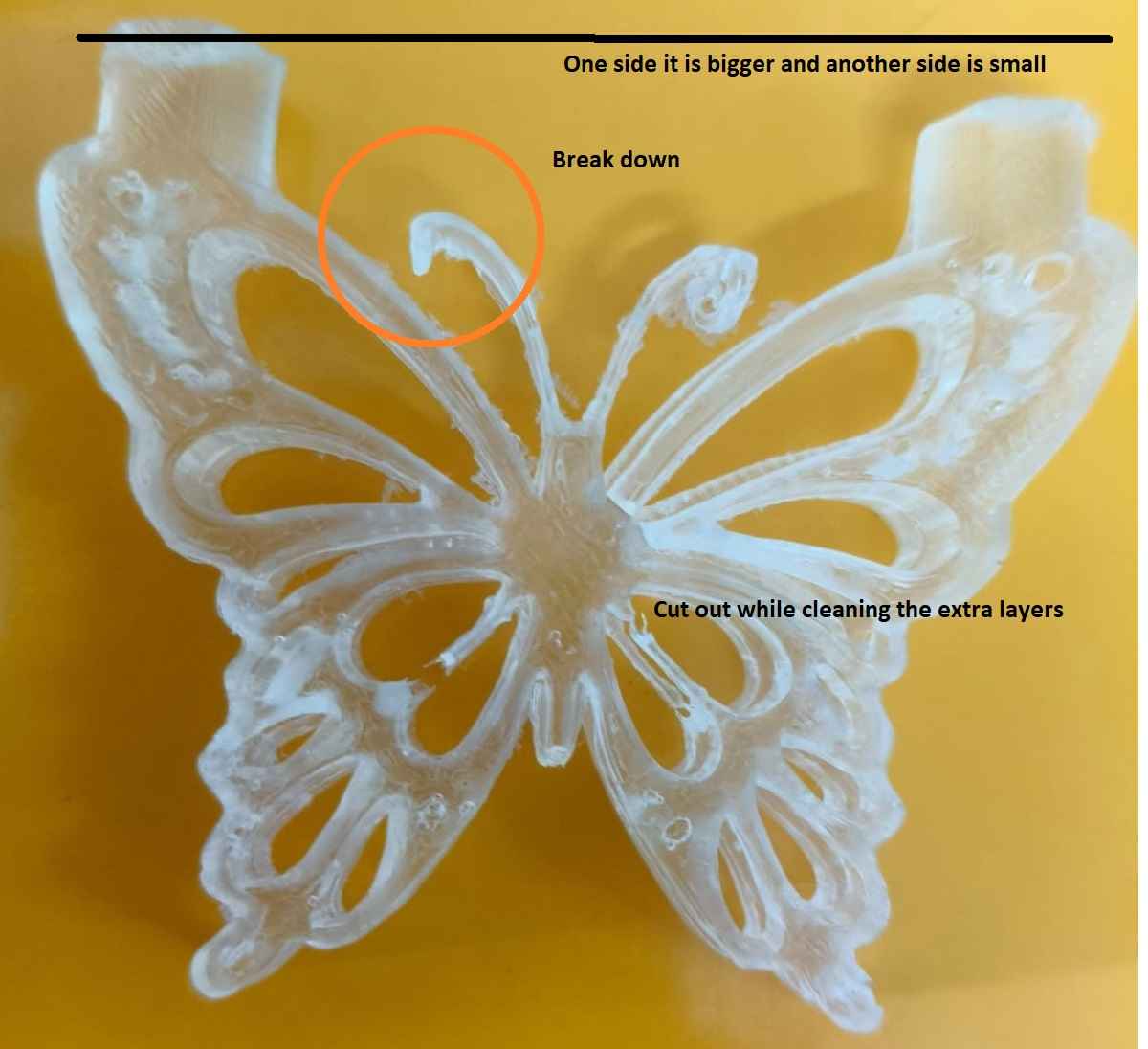
At the time of post processing, certain piece are break down due to thin layer and improper finishing observed during positive
In the beginning, I faced difficulty in understanding the casting process, especially steps like extruding the base and creating a negative mould. Since I was a beginner in 3D design, I found almost every part of the process a bit challenging. I also struggled with converting the STL file to G-code using the Anycubic slicer. However, with the continuous support and guidance of my instructor, I was able to overcome all these difficulties and complete the work successfully.
Through this activity, I learned the basics of 3D design and casting. I understood how to extrude shapes, create negative moulds, and convert STL files to G-code using the Anycubic slicer. I also learned how to troubleshoot problems and improved my skills with the help of my instructor. This experience increased my confidence in using design software and preparing files for 3D printing and casting.
Happy Learning
😀 Suith Mayakrishnan 😀