Measure the power consumption of an output device
This week, Dr. Shantanu Kadam and I focused on servo motor interfacing and measuring the power consumption of an output device using a DSO and multimeter. We were excited to dive into the hands-on aspects of this task, exploring the interfacing and analyzing power consumption in real-time.
Servo motor Interfacing
The servo motor has a fascinating history, starting from early attempts at precise control mechanisms in the 19th century to becoming an essential component in robotics and automation today.Thats why today i m trying today
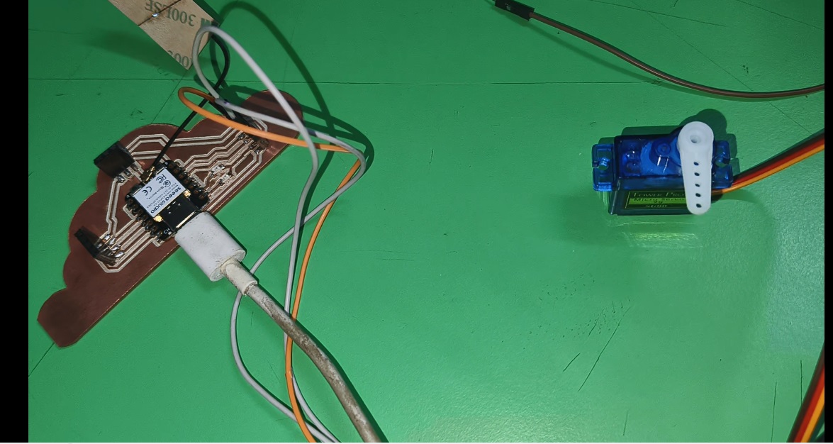
Connections:
Servo Signal Pin → Connect to D5 (XIAO ESP32C3)
Servo Power (VCC) → Connect to 5V (XIAO ESP32C3).
Servo Ground (GND) → Connect to ESP32-C3 GND.
To connect a servo motor to an XIAO ESP32C3, the general color coding is: red for power (5V), black or brown for ground (GND), and yellow, orange, or white for the signal wire.
For prgoramming Arduino IDE is used to program the XIAO ESP32C3. Servo motor interfacing program is given below
#includeServo myServo; #define SERVO_PIN 6 // Adjust based on your setup void setup() { myServo.attach(SERVO_PIN); Serial.begin(115200); } void loop() { for (int angle = 0; angle <= 180; angle += 10) { myServo.write(angle); Serial.print("Servo Angle: "); Serial.println(angle); delay(500); } for (int angle = 180; angle >= 0; angle -= 10) { myServo.write(angle); Serial.print("Servo Angle: "); Serial.println(angle); delay(500); } }
After connection and uploaded the above code to observe the DSO response and Multimeter
Observing the various step angles with respect to the changes in pulse sending to the step motor using the DSO was particularly insightful. We closely monitored how adjustments in pulse frequency and width affected the step resolution, noting the nuances in motor response at different settings. The real-time waveforms displayed by the DSO allowed us to correlate the precise timing of the pulses with the motor’s angular displacement, enabling a deeper understanding of the stepping mechanics.
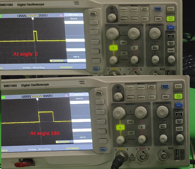
While measuring using the multimeter, we observed that the stepper motor delivered a maximum voltage of 3.13V when the step angle was at 0°. As the step angle increased, the voltage steadily dropped, reaching a minimum of 2.89V at an angle of 180°. This observation was fascinating as it revealed the motor’s inherent behavior in response to changing angles, suggesting that the motor's performance characteristics and internal circuitry might contribute to this voltage variation.
Learning outcomes
🙂 Happy Group Learning 🙂
🙂 Sujith Mayakrishnan 🙂