Week 15: System Integration
System integration is a critical aspect of any project, especially in the context of creating a cohesive and functional final product. The goal is to ensure that all components—hardware, software, and mechanical—work seamlessly together, resulting in a polished and professional output. This section outlines the design, methods, and considerations taken during the system integration phase of the project.
Methods of Packaging
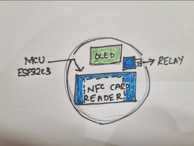
Packaging is an integral aspect of designing any hardware project, as it not only protects the internal components but also ensures that the product is aesthetically pleasing and user-friendly. For this project, the packaging was designed to house several critical components, including the ESP32-C3 microcontroller, an OLED screen, a relay module, and an RFID card reader module. Below is an in-depth discussion of the packaging methods implemented to safeguard these components and enhance the overall presentation of the product.
Enclosure Design
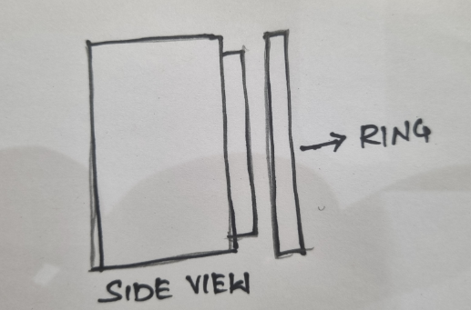
The enclosure was meticulously designed to accommodate all the internal components securely while ensuring ease of assembly and maintenance. The design process included the following considerations:
- Dimensions: The dimensions of the enclosure were tailored to fit the ESP32-C3 microcontroller, OLED screen, relay module, and RFID card reader module. Adequate space was allocated for wiring and other connectors.
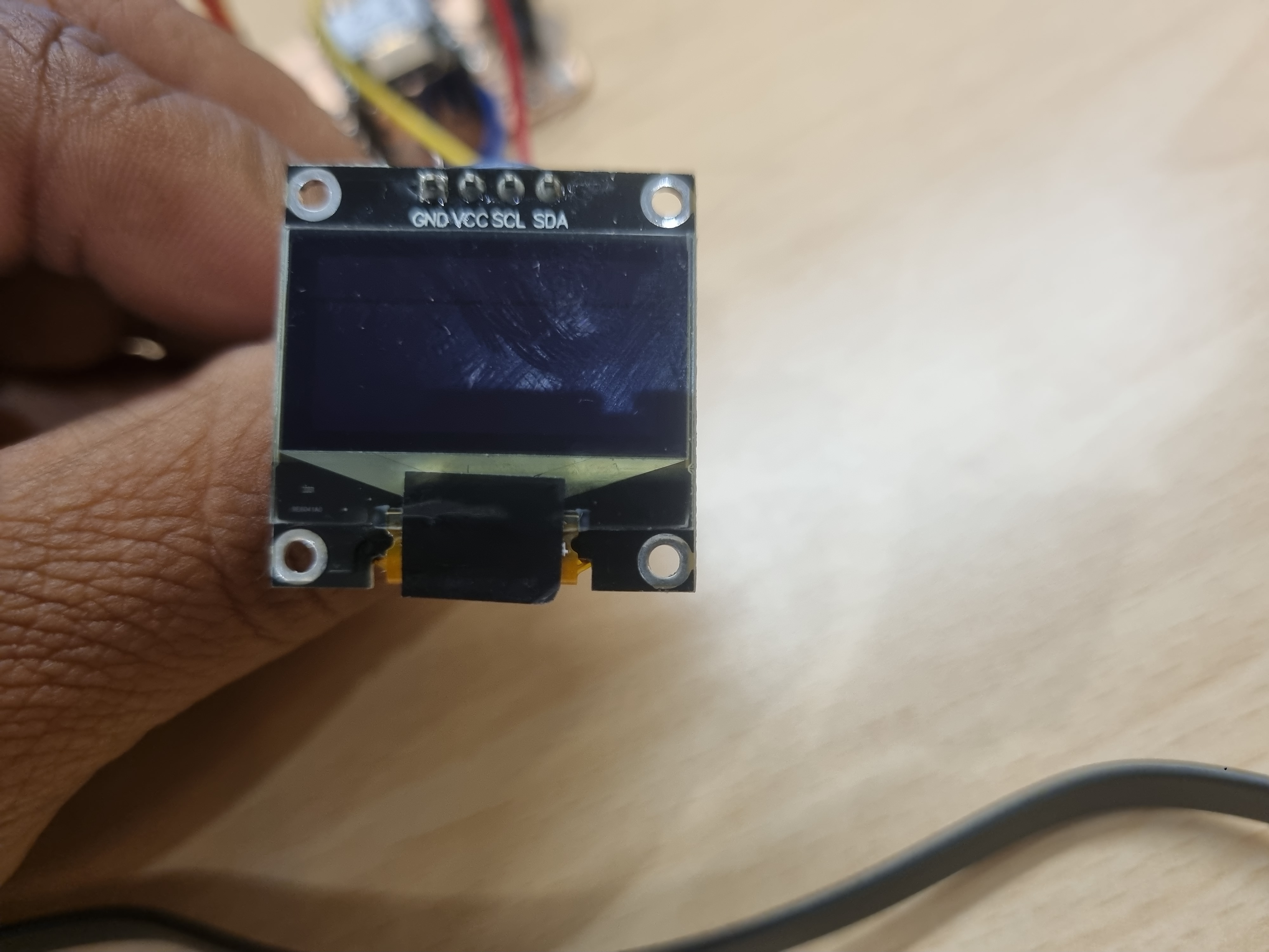
- Component Placement: Each component was strategically positioned to optimize space and functionality. For instance, the OLED screen was placed on the front panel for user interaction, while the RFID card reader was positioned on an accessible side to allow seamless card scanning.
- Ventilation: Slots and perforations were incorporated into the design to ensure adequate airflow and prevent overheating of components, especially during prolonged operation.
- Access Points: The enclosure featured cutouts for power cables, USB connections, and antenna placement, ensuring that all external interfaces were easily accessible.
Cable Management
Proper cable management was vital to maintain the functionality and safety of the device. The following strategies were implemented:
- Organized Wiring: All internal wiring was routed using cable ties and adhesive clips to minimize clutter. This approach not only improved the aesthetic appeal but also reduced the risk of accidental disconnections or electrical shorts.
- Labeling: Each wire was labeled to simplify troubleshooting and future modifications. Labels indicated the connection points for components like the relay module and OLED screen.
- Shielded Cables: Where possible, shielded cables were used to minimize electromagnetic interference, ensuring reliable communication between the microcontroller and peripherals such as the RFID card reader.
Material Selection
The material for the enclosure played a critical role in determining the durability and overall quality of the packaging. High-durability PLA (Polylactic Acid) was chosen for the following reasons:
- Strength and Durability: PLA offers sufficient strength to protect the internal components from physical damage during regular use.
- Environmental Friendliness: As a biodegradable material, PLA aligns with sustainable design principles, making it an eco-friendly choice.
- Ease of Printing: PLA is compatible with most 3D printers, enabling the creation of detailed and precise enclosures with a smooth finish.
- Thermal Stability: The material can withstand moderate temperatures, making it suitable for housing electronic components like the ESP32-C3.
Components Inside the Enclosure
The enclosure housed several critical components, each of which required specific considerations for placement and integration:
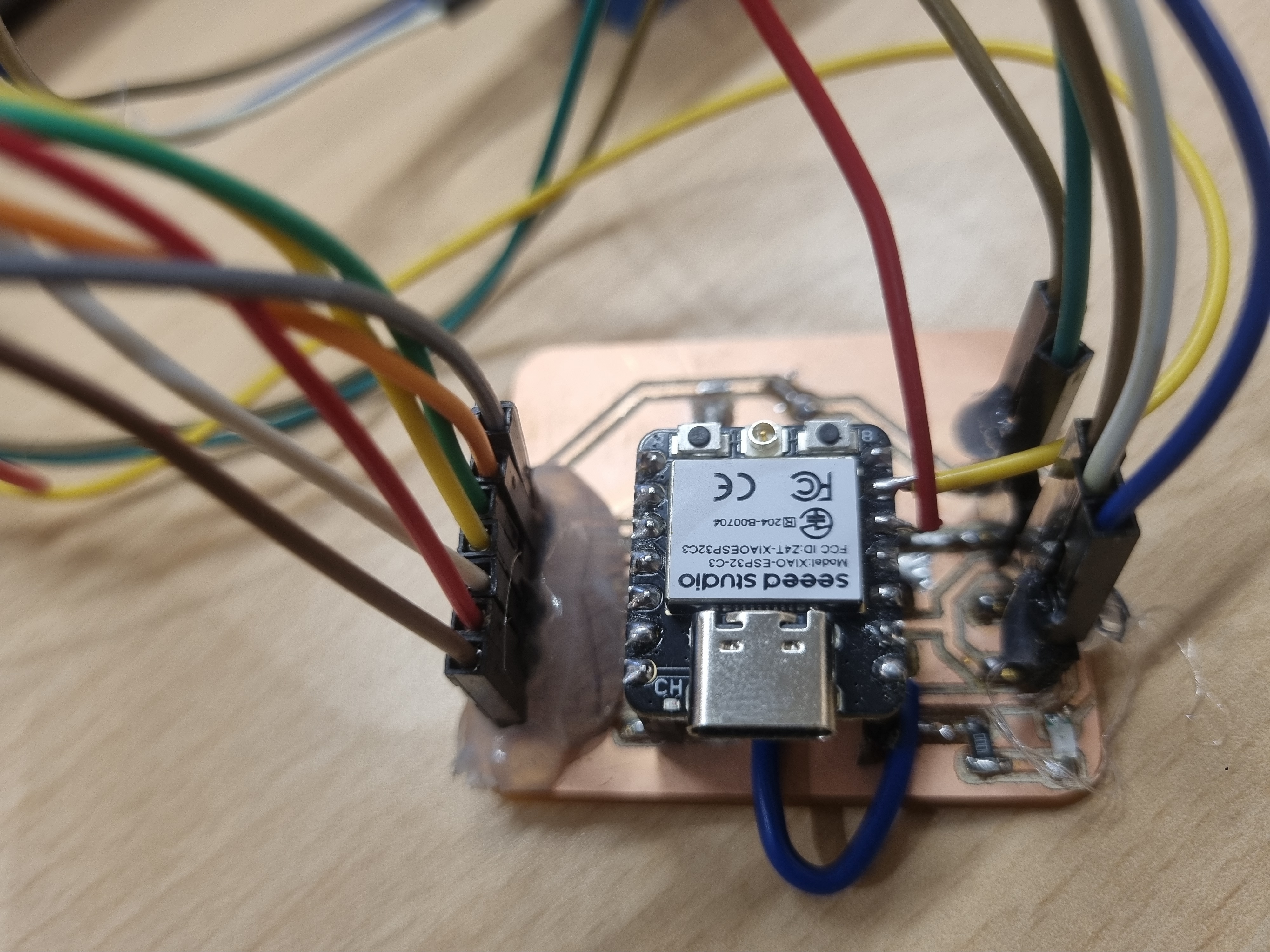
- ESP32-C3 Microcontroller: This microcontroller served as the brain of the system, managing all interactions between the UI, relay, OLED screen, and RFID card reader. It was secured using mounting screws to ensure stability and prevent vibrations during operation.
- OLED Screen: Positioned on the front panel, the OLED screen provided real-time feedback to the user. Its placement ensured visibility while maintaining a clean layout. A transparent cover was added to protect the screen from dust and scratches.
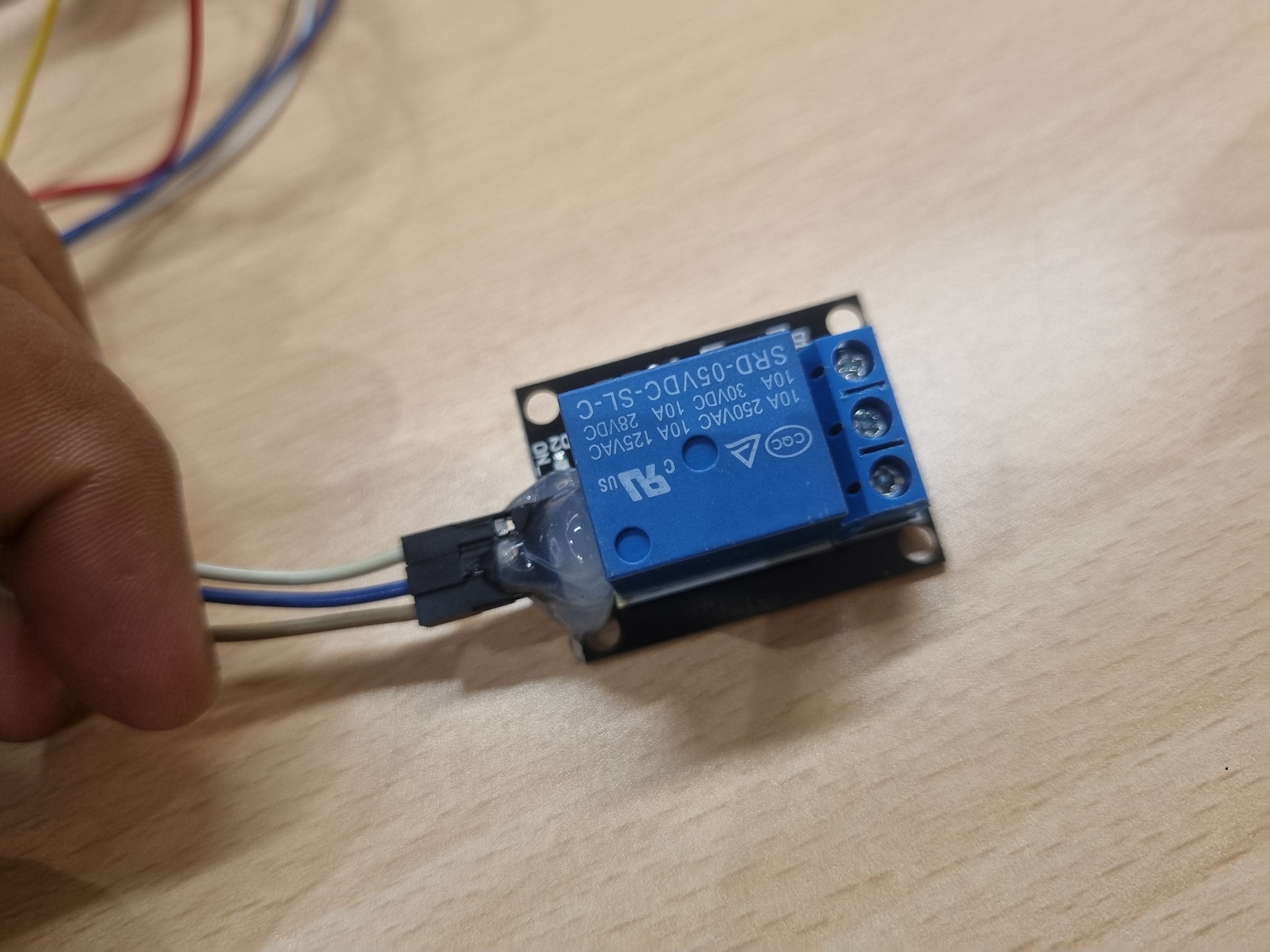
- Relay Module: The relay module was mounted in a corner of the enclosure to minimize electromagnetic interference with other components. A secure connection to the ESP32-C3 ensured reliable switching operations.
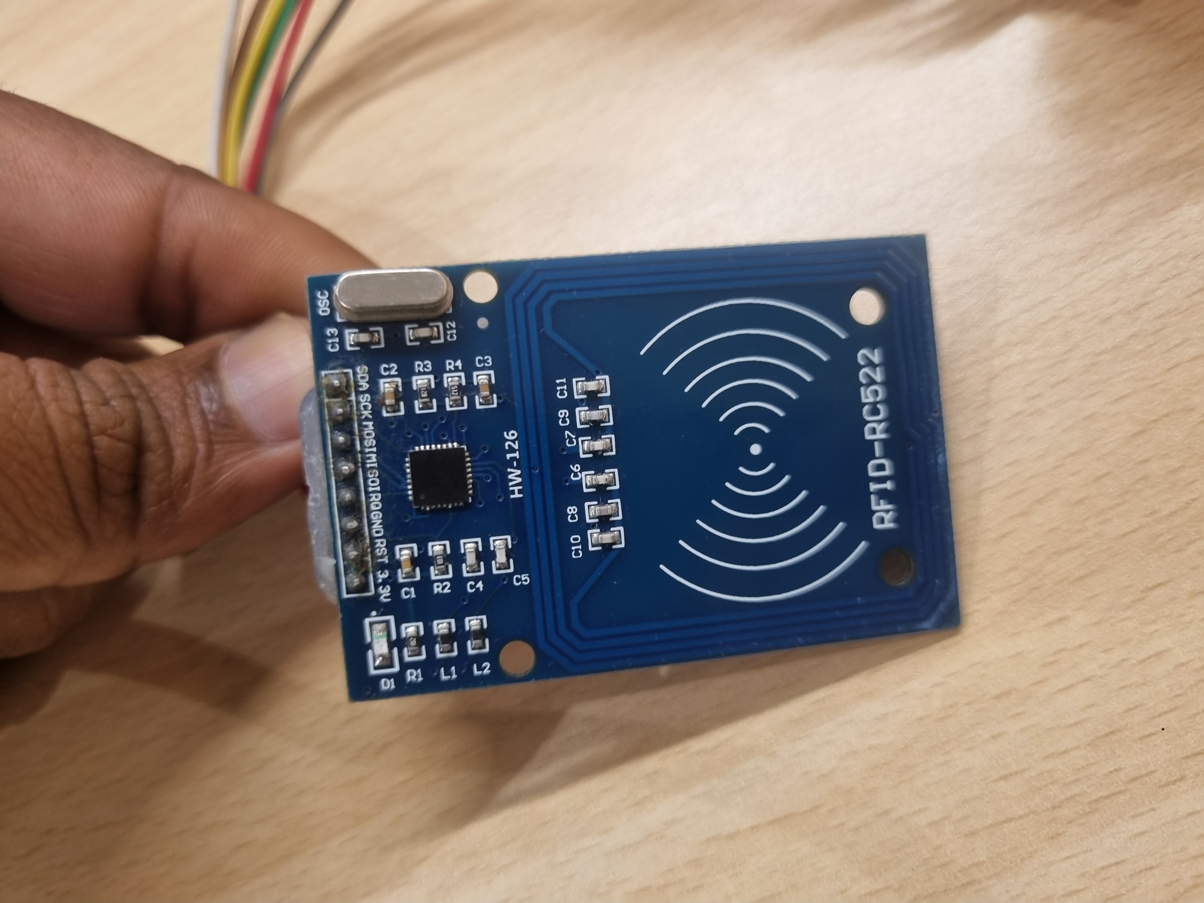
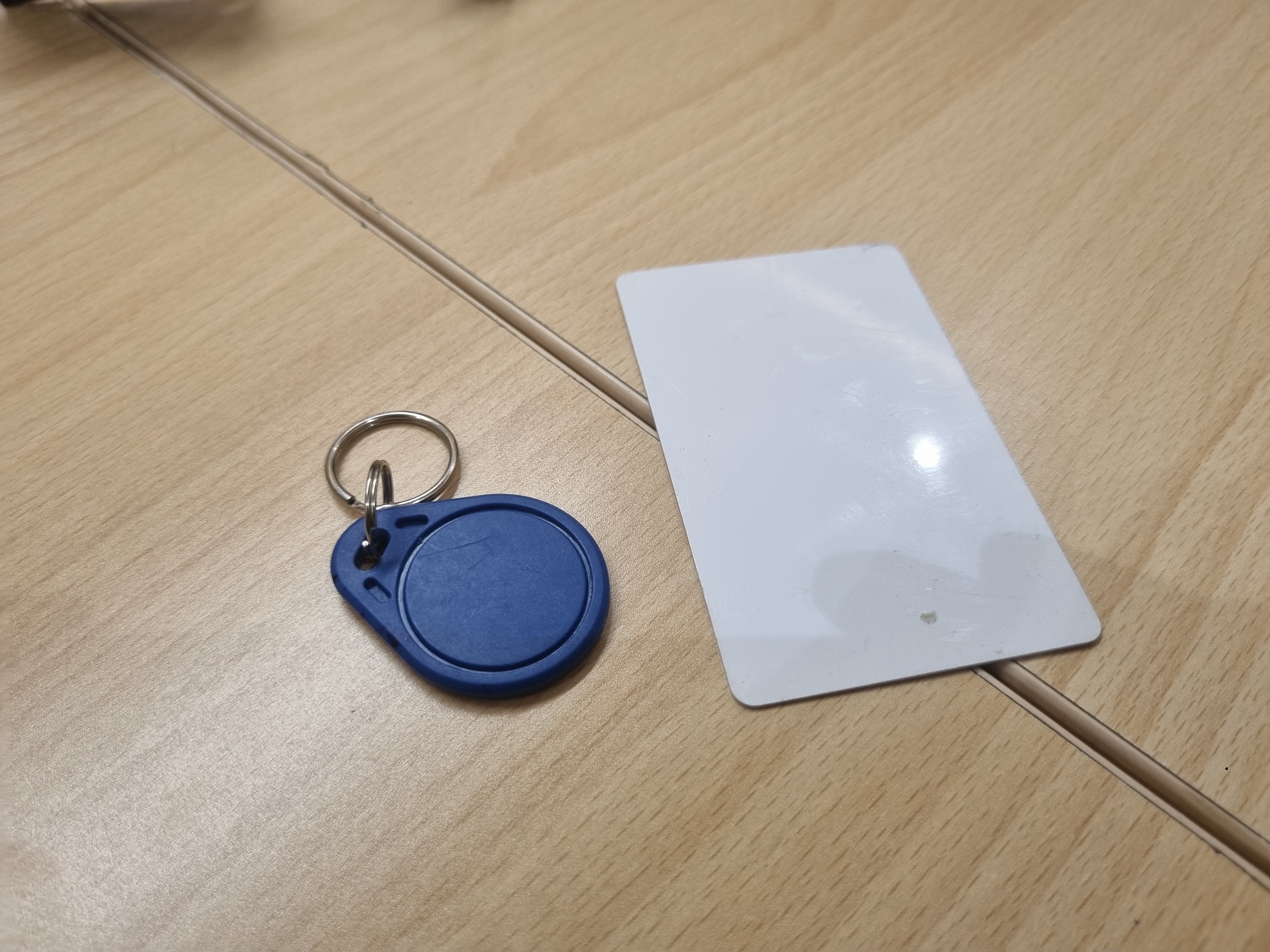
- RFID Card Reader Module: The RFID reader was mounted near the enclosure's surface to allow easy scanning of RFID cards. Care was taken to ensure the antenna had adequate space to function optimally, with minimal interference from other components.
Final Product Design
The final product was designed to have a professional and user-friendly appearance. Specific efforts were made to ensure it looked and felt like a finished product:
- Ergonomics: The enclosure was designed with rounded edges and a compact form factor for easy handling and placement.
- Visual Appeal: The enclosure was finished with a matte coating to enhance its aesthetic appeal. The LED indicators were strategically positioned for clear visibility.
- User Interface: The integrated web-based UI allowed users to interact with the system seamlessly. The responsive design ensured compatibility across devices, from desktops to smartphones.
System Integration Documentation
The system integration process involved the following key steps:
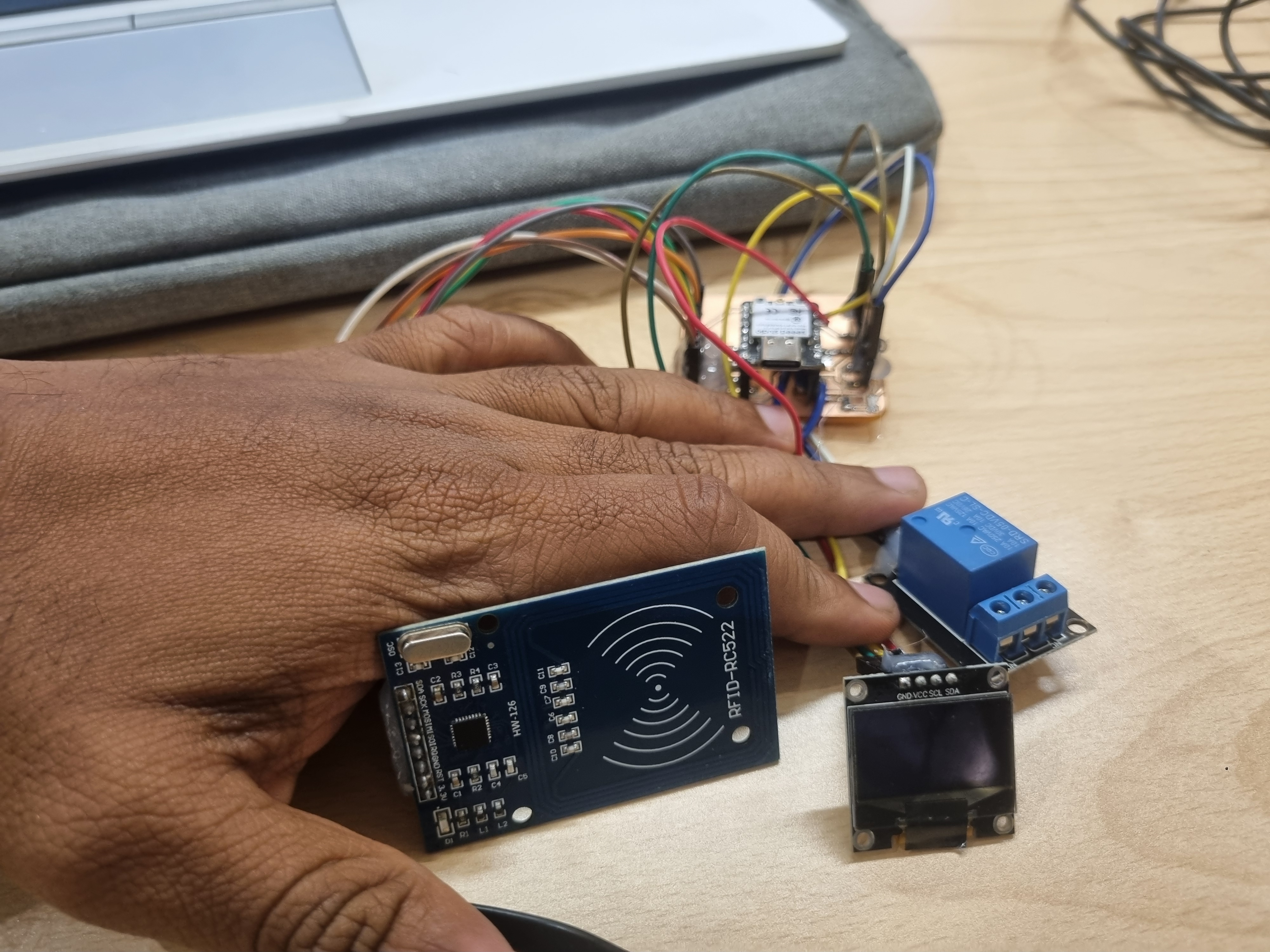
- Hardware Integration: All components, including the ESP32-C3 microcontroller, relay module, and power supply, were interconnected following a structured wiring diagram. Rigorous testing ensured that the components worked together without conflicts or failures.
- Software Integration: The firmware was developed to handle multiple tasks, including HTTP requests from the web-based UI, controlling the LED, and providing status feedback. The code was modular, enabling easy debugging and future scalability.
- Testing and Troubleshooting: The integrated system was subjected to extensive testing under various conditions. Issues such as network latency and component synchronization were identified and resolved during this phase.
Link to Final Project Documentation
The detailed documentation of the system integration process has been linked to the final project page for reference. This includes design files, schematics, source code, and a ‘hero shot’ showcasing the completed project in action.
This comprehensive approach to system integration ensured the final project met all technical and aesthetic requirements, delivering a high-quality and functional product.