Week 14: Interface and Application Programming
This page documents the process of designing and implementing a user interface (UI) that communicates with an embedded microcontroller board I designed and built. The goal is to create an intuitive application that bridges the user with the input and/or output devices connected to the board.
Group Assignment
In the group assignment, we explored various tools and frameworks for creating user interfaces and applications. Our goal was to compare as many options as possible, considering factors like ease of use, compatibility with microcontrollers, and programming flexibility.
- Compared UI frameworks such as Python’s
Tkinter,PyQt, andKivy. - Explored web-based UI options using HTML, CSS, and JavaScript.
- Documented tool pros and cons, including learning curves, platform support, and communication protocols.
The comparison provided valuable insights into the versatility and limitations of various tools, helping each team member choose the most suitable approach for their individual assignments.
.Visit our Group Assignment Page to explore our findings and methodologies.
Individual Assignment
For my individual assignment, I created an application that interfaces with an embedded microcontroller board. The application enables the user to interact with a connected output device—a 5V single-channel relay module—through an intuitive interface.
Application Design
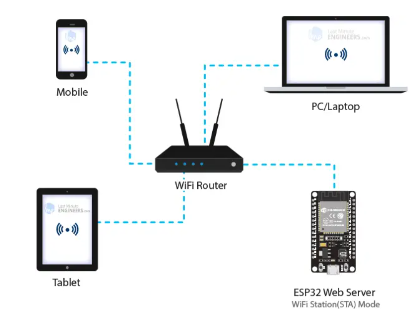
In this project, a web-based application running directly on an ESP32-C3 microcontroller was used to control an LED connected to one of its GPIO pins. This approach leveraged the ESP32-C3's built-in WiFi capabilities to host a web server, allowing users to access the interface from any device with a web browser.

The application interface was designed using HTML and CSS, with a focus on simplicity and accessibility. The interface comprises two buttons: one for turning the LED ON and another for turning it OFF. Each button is color-coded (green for ON, red for OFF) to provide intuitive visual feedback. The layout ensures that the application is responsive and user-friendly on both desktop and mobile devices.
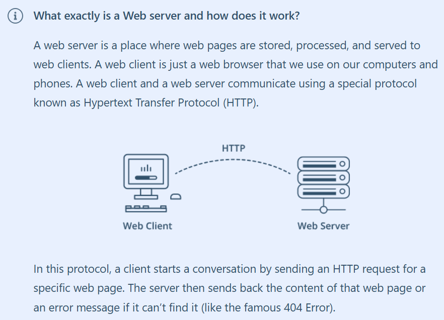
The backend logic of the application resides on the ESP32-C3, which acts as the web server. When a user interacts with the buttons on the web page, corresponding HTTP requests are sent to the ESP32-C3. These requests are handled by predefined endpoints (/on and /off) in the ESP32-C3's firmware. Upon receiving a request, the ESP32-C3 executes the appropriate action: setting the GPIO pin to HIGH to turn the LED ON or LOW to turn it OFF.
This method of control eliminates the need for an external desktop application or specialized software. Instead, the entire control logic and user interface are integrated within the ESP32-C3 itself. This approach also ensures platform independence, as the interface can be accessed from any device with a web browser, including smartphones, tablets, and laptops.
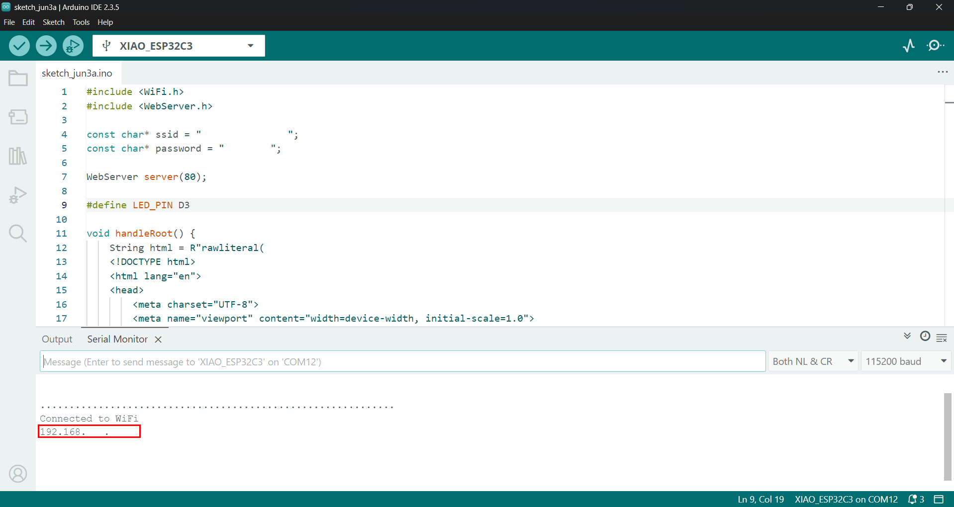
A key advantage of using an HTML-based interface hosted on the ESP32-C3 is its portability and ease of use. The user only needs to connect to the ESP32-C3's IP address (displayed in the Serial Monitor after booting up the ESP32) to control the device. This simplicity makes it ideal for IoT applications where remote control and ease of deployment are critical.
Additionally, the interface was designed with a focus on aesthetics. The buttons include hover effects and an active state animation to enhance user experience. Inline CSS was used for styling to maintain simplicity in the project structure. The ESP32-C3 serves the static HTML and CSS files directly to the client’s browser, making the deployment of the interface seamless.
By combining the ESP32-C3's powerful microcontroller features with its built-in WiFi module, this project demonstrates a highly effective way to interface a user with an embedded system. This approach not only highlights the versatility of the ESP32-C3 but also showcases how web technologies can be seamlessly integrated into embedded applications to provide robust, accessible, and user-friendly control interfaces.
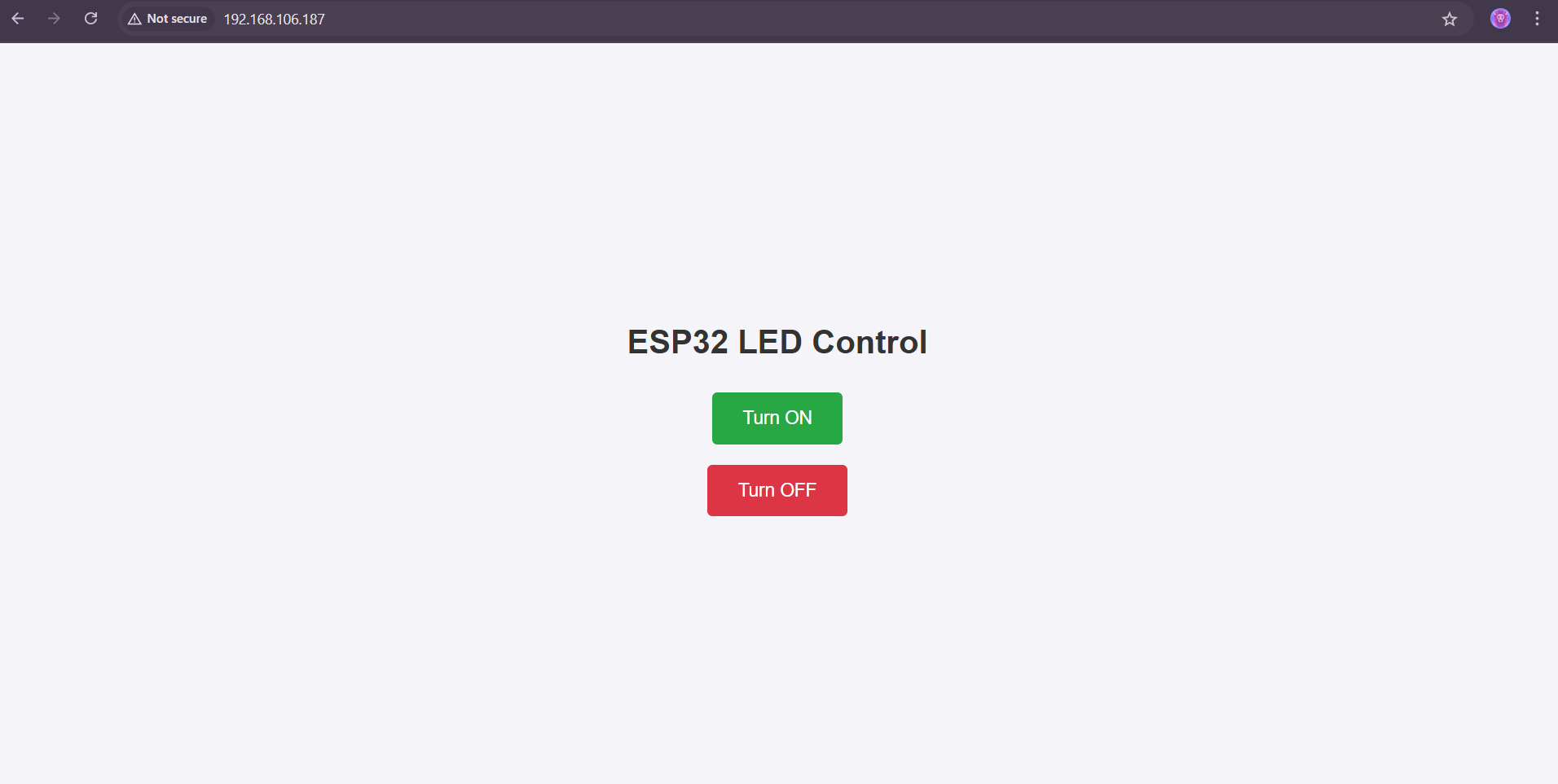
The application was styled to ensure clarity and usability, with a focus on a responsive layout and clear status indicators.
Communication with the Microcontroller
In this project, communication between the web-based application and the ESP32-C3 microcontroller is established using HTTP requests over WiFi. This method ensures efficient, real-time control and monitoring of the connected devices. The ESP32-C3 serves as the core of the system, acting as both a web server and a device controller.
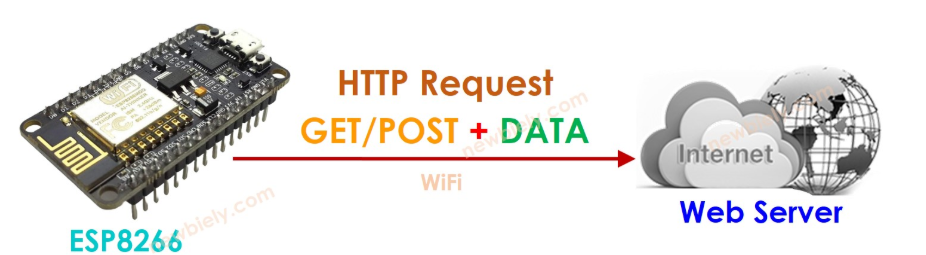
The communication protocol involves sending specific HTTP requests to predefined endpoints hosted on the ESP32-C3. These endpoints correspond to specific actions for the LED connected to the microcontroller. For instance:
-
A
GETrequest to the/onendpoint instructs the ESP32-C3 to turn the LED ON. Upon receiving this request, the microcontroller sets the designated GPIO pin (in this case, pin D3) to a HIGH state, effectively powering the LED. -
Similarly, a
GETrequest to the/offendpoint turns the LED OFF by setting the GPIO pin to a LOW state.
The ESP32-C3 is programmed to provide acknowledgments for each action performed. For example, after processing a request to turn the LED ON, the microcontroller responds with a simple HTML response or status message such as "LED is ON." This acknowledgment is sent back to the browser, confirming that the action has been successfully executed. This feedback loop ensures that users are always informed about the current state of the system.
One of the significant advantages of this communication method is its simplicity and reliability. HTTP is a well-established protocol, widely supported across all modern web browsers and devices. By hosting the application directly on the ESP32-C3, users can control the microcontroller without the need for additional software or configurations. Accessing the application is as simple as entering the ESP32-C3's IP address in a web browser, which makes the system highly user-friendly.
The use of HTTP also provides flexibility for future expansion. For example, the ESP32-C3 can be configured to support additional endpoints for more complex operations or to communicate with other web-based applications or services. Furthermore, since HTTP is platform-independent, the same application can be accessed from any device, including smartphones, tablets, and desktop computers.
The simplicity of the commands used in this communication process enhances its robustness. By using easily interpretable ASCII commands such as /on and /off, the system minimizes the risk of errors and ensures that commands are correctly processed. The feedback mechanism further strengthens this reliability by providing users with real-time updates on the status of the LED.
Overall, the communication architecture in this project demonstrates how straightforward yet effective design principles can be used to interface a user application with an embedded system. By leveraging the ESP32-C3's built-in WiFi capabilities and the universality of HTTP, the project achieves a seamless and efficient communication mechanism, highlighting the potential of web-based control interfaces in embedded applications.
Process Documentation
The development process for the LED control system using an ESP32-C3 board and a web-based interface involved several key steps. These steps ensured a robust, user-friendly, and reliable system for controlling the LED.
1. Setting Up the Microcontroller
The first step was to configure the ESP32-C3 microcontroller to respond to HTTP requests and control the LED connected to GPIO pin D3. The microcontroller was programmed using the Arduino IDE with the ESPAsyncWebServer library, which allows efficient handling of web server requests. The pin connected to the LED was initialized as an output pin.
The web server hosted on the ESP32-C3 was configured to include two endpoints: /on and /off. These endpoints corresponded to the commands to turn the LED ON and OFF, respectively. A basic HTML interface was designed to send these requests from the user's web browser.
2. Designing the Web Interface
The HTML interface for controlling the LED was designed to be simple yet visually appealing. Using CSS for styling, the interface included two buttons labeled "Turn ON" and "Turn OFF." These buttons triggered the respective HTTP requests to control the LED state. The interface was embedded directly into the ESP32-C3 code, allowing it to be hosted as part of the web server.
The following is a snippet of the web interface code:
3. Testing and Debugging
The next step was to test the system to ensure proper communication and functionality. After uploading the code to the ESP32-C3 board, the system was connected to a WiFi network. The IP address of the ESP32-C3 was used to access the web interface via a browser.
Testing involved verifying that the LED responded to the "Turn ON" and "Turn OFF" buttons. Debugging was performed to ensure there were no errors in the HTTP request handling or GPIO control logic. Common issues encountered included incorrect pin configuration and intermittent network connectivity, which were resolved through careful analysis and iterative testing.
4. Source Code for the ESP32
The following is the complete Arduino code for the ESP32-C3 to host the web server and control the LED:
#include
#include

const char* ssid = "Your_SSID";
const char* password = "Your_PASSWORD";

const int ledPin = 3;

AsyncWebServer server(80);

void setup() {
  pinMode(ledPin, OUTPUT);
  digitalWrite(ledPin, LOW);

  WiFi.begin(ssid, password);
  while (WiFi.status() != WL_CONNECTED) {
    delay(1000);
  }

  server.on("/on", HTTP_GET, [](AsyncWebServerRequest *request){
    digitalWrite(ledPin, HIGH);
    request->send(200, "text/plain", "LED is ON");
  });

  server.on("/off", HTTP_GET, [](AsyncWebServerRequest *request){
    digitalWrite(ledPin, LOW);
    request->send(200, "text/plain", "LED is OFF");
  });

  server.on("/", HTTP_GET, [](AsyncWebServerRequest *request){
    request->send(200, "text/html", R"rawliteral(
    )rawliteral");
  });

  server.begin();
}

void loop() {
}
Challenges and Solutions
During the development of the LED control system using the ESP32-C3 microcontroller and web-based interface, several challenges were encountered. These challenges primarily arose from the communication between the web interface, the microcontroller, and the GPIO pin controlling the LED. Each issue required specific debugging and optimization efforts to ensure a seamless user experience. Below are the key challenges and the solutions implemented to address them.
1. Serial Communication Delays
Challenge: One of the primary challenges was managing serial communication delays between the microcontroller and the client. Delays often caused the application to freeze during read/write operations, particularly when the server had to respond to multiple HTTP requests in quick succession. These delays disrupted the real-time responsiveness required for smooth LED control.
Solution: To mitigate these delays, a timeout mechanism was implemented in the code. This mechanism ensures that the server does not wait indefinitely for a response. Additionally, non-blocking I/O operations were introduced to maintain the server's responsiveness. Non-blocking I/O allows the ESP32 to handle multiple tasks simultaneously, such as serving HTTP requests and controlling the LED, without being held up by slower operations. This approach significantly improved the system's reliability and user experience.
2. Synchronization Issues
Challenge: Synchronization problems occurred between the commands sent from the web interface and their execution on the ESP32. For example, the LED's state sometimes did not reflect the latest command, leading to confusion about whether the device was responding accurately.
Solution: A command-response protocol was implemented to ensure synchronization between the web interface and the ESP32. Each command, such as /on or /off, triggered an immediate response from the microcontroller confirming the action. For instance, when the user clicked "Turn ON," the ESP32 not only turned the LED on but also sent back a response like "LED is ON." This feedback loop allowed the interface to display the current status of the LED reliably, enhancing user confidence in the system's operation.
3. Network Connectivity Challenges
Challenge: Establishing and maintaining a stable connection to the WiFi network posed occasional challenges. Weak signals or temporary disconnections interrupted the communication between the web interface and the ESP32.
Solution: To address connectivity issues, the ESP32 was programmed with a reconnect mechanism. If the WiFi connection was lost, the microcontroller attempted to reconnect automatically. Status indicators were also added to notify the user of the connection state, enabling better troubleshooting in the event of persistent network problems.
4. Debugging and Testing the System
Challenge: Debugging the system to identify the root cause of issues was often time-consuming. Problems such as incorrect GPIO pin configurations or faulty LED connections could disrupt the system's functionality.
Solution: Rigorous testing was carried out for each component individually and as part of the entire system. Test cases included simulating multiple HTTP requests, checking the LED response to commands, and verifying network stability. These tests were invaluable in identifying and resolving issues early in the development cycle.
Learning Outcomes
This assignment provided a deep understanding of user interface design and the integration of communication protocols with microcontroller boards. Key takeaways include:
- Implementing a Functional UI Using HTML: The UI was developed as a web application hosted directly on the ESP32-C3 microcontroller. This approach eliminated the need for additional software or external devices, making the system highly self-contained. The HTML-based interface provided buttons for toggling the LED and real-time feedback to indicate the current status of the device.
- Understanding and Applying HTTP Communication Protocols: The communication between the user and the ESP32-C3 microcontroller was facilitated through HTTP requests. Clicking a button on the web interface triggered a corresponding HTTP GET request that the microcontroller processed, enabling or disabling the LED accordingly.
- Troubleshooting and Resolving Hardware-Software Interaction Issues: Challenges such as handling asynchronous HTTP requests and ensuring reliable operation under varying network conditions were addressed through careful coding and testing. These efforts ensured smooth and efficient communication between the web interface and the microcontroller hardware.
This assignment emphasized the seamless integration of hardware and software components using modern web technologies, showcasing the versatility and capability of the ESP32-C3 microcontroller.
Hero Shot
Below is a hero shot of the application running and successfully toggling the relay:
Conclusion
This project was a comprehensive exercise in bridging hardware and software using an intuitive user interface. The skills gained will be instrumental in future projects involving microcontroller applications and embedded systems development.