Week11: Embedded Networking and Communications
We have sent a message between two projects, documented the process on the group work page, and reflected on our learning on individual pages.
Visit our Group Assignment Page to explore our findings and methodologies.
Individual Assignment
This assignment focuses on designing, building, and connecting a wired or wireless node with network or bus addresses and a local input/output device. The task specifically involves using the I2C communication protocol to interface an OLED display with the ESP32-C3 board from Seeed Studio. This exercise emphasizes the implementation and interpretation of I2C communication, as well as ensuring proper addressing of connected devices.
Communication Protocols in Electronics
Communication protocols are essential in electronics for transferring data between devices like microcontrollers, sensors, and actuators. The three most common protocols are SPI, I2C, and UART, each with unique characteristics and applications.
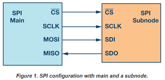
Serial Peripheral Interface (SPI)
SPI is a high-speed, full-duplex communication protocol commonly used for short-distance communication between a microcontroller and peripherals like sensors, SD cards, and displays. It uses four main lines:
- MOSI: Master Out Slave In for data sent from the master.
- MISO: Master In Slave Out for data received by the master.
- SCLK: Serial Clock, controlled by the master.
- SS: Slave Select for enabling specific devices on the bus.
SPI is favored for its simplicity and speed but requires more pins than other protocols.
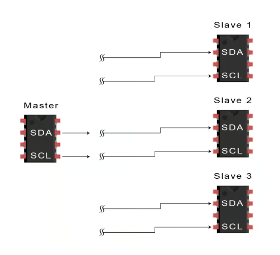
Inter-Integrated Circuit (I2C)
I2C is a multi-master, multi-slave protocol designed for communication between components on a single PCB. It operates using two lines:
- SDA: Serial Data Line for transmitting data.
- SCL: Serial Clock Line for synchronizing communication.
I2C supports multiple devices with unique addresses on the same bus, making it ideal for complex systems with limited pin availability.
Universal Asynchronous Receiver Transmitter (UART)
UART is a hardware communication protocol that operates asynchronously, meaning it doesn’t require a clock line. Data is transmitted using:
- TX: Transmit data line.
- RX: Receive data line.
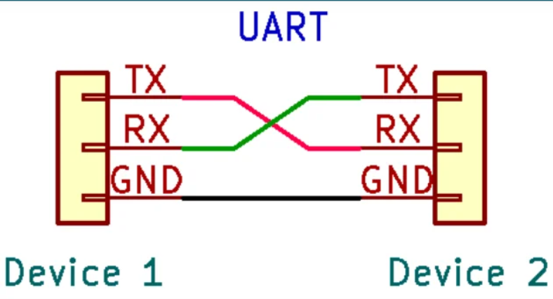
UART is commonly used for serial communication in applications like debugging, GPS modules, and wireless communication modules. Its simplicity and minimal hardware requirements make it versatile, though it is generally slower than SPI and I2C.
Comparison
| Protocol | Speed | Lines | Use Case |
|---|---|---|---|
| SPI | High | 4+ | High-speed peripherals |
| I2C | Medium | 2 | Multi-device communication |
| UART | Low | 2 | Debugging, basic serial comms |
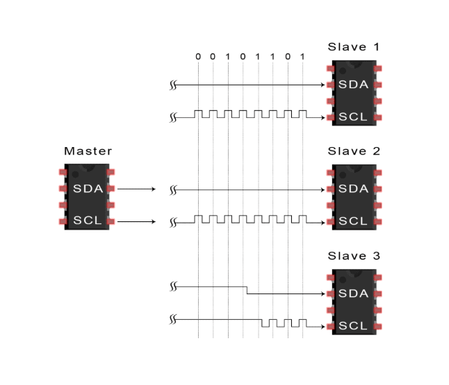
Understanding I2C Communication
I2C (Inter-Integrated Circuit) is a two-wire communication protocol that enables multiple devices to communicate on a shared bus. It uses two lines: SCL (Serial Clock Line) for clock signals and SDA (Serial Data Line) for data transfer. Each device on the I2C bus has a unique 7-bit or 10-bit address, enabling the master (e.g., ESP32-C3) to communicate with specific devices (e.g., OLED display) without conflicts.
I2C is widely used in embedded systems due to its simplicity, scalability, and low pin count. The protocol supports multiple masters and slaves, allowing seamless integration of sensors, displays, and other peripherals.
Steps of I2C Data Transmission 1. The master sends the start condition to every connected slave by switching the SDA line from a high voltage level to a low voltage level before switching the SCL line from high to low:
2. The master sends each slave the 7 or 10 bit address of the slave it wants to communicate with, along with the read/write bit:
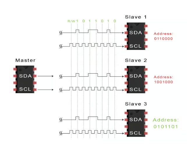
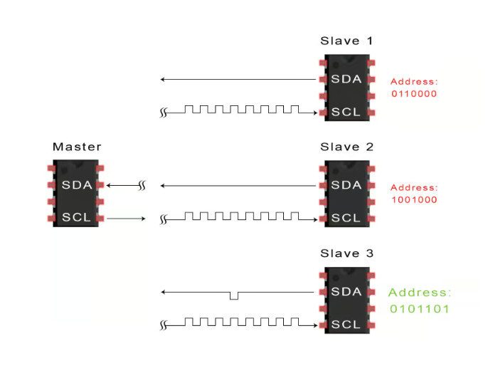
3. Each slave compares the address sent from the master to its own address. If the address matches, the slave returns an ACK bit by pulling the SDA line low for one bit. If the address from the master does not match the slave’s own address, the slave leaves the SDA line high.
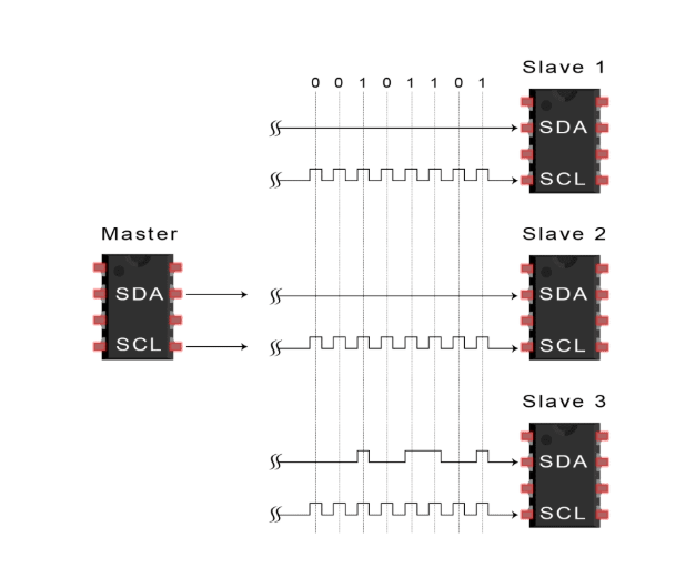
4. The master sends or receives the data frame:
5. After each data frame has been transferred, the receiving device returns another ACK bit to the sender to acknowledge successful receipt of the frame:
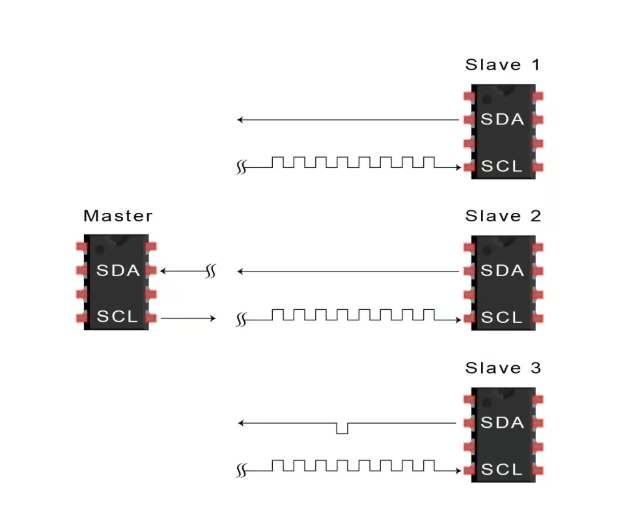
6. To stop the data transmission, the master sends a stop condition to the slave by switching SCL high before switching SDA high:
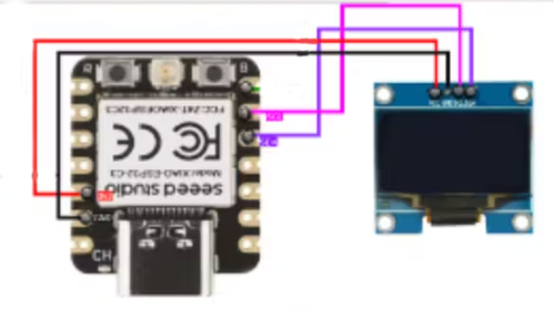
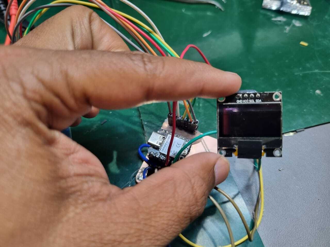
Hardware Setup
The hardware setup involves connecting the ESP32-C3 microcontroller to an OLED display via the I2C protocol. The key components used are:
- ESP32-C3: A compact and powerful microcontroller with built-in Wi-Fi and BLE, ideal for IoT applications.
- OLED Display: A small, high-contrast display module supporting I2C communication, typically operating at 3.3V or 5V.
The connection details are as follows:
- SCL: Connect to GPIO 22 (default I2C clock line on ESP32-C3).
- SDA: Connect to GPIO 21 (default I2C data line on ESP32-C3).
- VCC: Connect to the 3.3V power output of the ESP32-C3.
- GND: Connect to the common ground.
To ensure reliable communication, pull-up resistors (typically 4.7kΩ) are connected to the SCL and SDA lines. These resistors ensure proper logic levels for I2C signals.
Software Workflow
The software development process includes initializing the I2C bus, addressing the OLED display, and sending commands and data. The workflow involves the following steps:
1. Initializing the I2C Bus
The ESP32-C3’s Wire library is used to initialize the I2C bus. The Wire.begin(SDA, SCL) function sets up the communication, where SDA
and SCL are the respective GPIO pins.
2. Addressing the OLED Display
The OLED display’s I2C address is typically 0x3C or 0x3D, depending on the module. A scan function can be implemented to identify the address dynamically. The display is then addressed using the Wire library.
3. Sending Commands and Data
The Adafruit GFX and SSD1306 libraries are used for rendering graphics and text on the OLED. Functions like display.print() and display.drawLine()
simplify content creation. The code snippet below demonstrates basic initialization and content rendering:
#include SPI.h
#include Wire.h
#include Adafruit_GFX.h
#include Adafruit_SSD1306.h
#include MFRC522.h
#define SCREEN_WIDTH 128
#define SCREEN_HEIGHT 64
#define OLED_RESET -1
#define SCREEN_ADDRESS 0x3C
Adafruit_SSD1306 display(SCREEN_WIDTH, SCREEN_HEIGHT, &Wire, OLED_RESET);
void setup() {
if (!display.begin(SSD1306_I2C_ADDRESS, SCREEN_ADDRESS)) {
while (true);
}
display.clearDisplay();
display.setTextSize(1);
display.setTextColor(SSD1306_WHITE);
display.setCursor(0, 0);
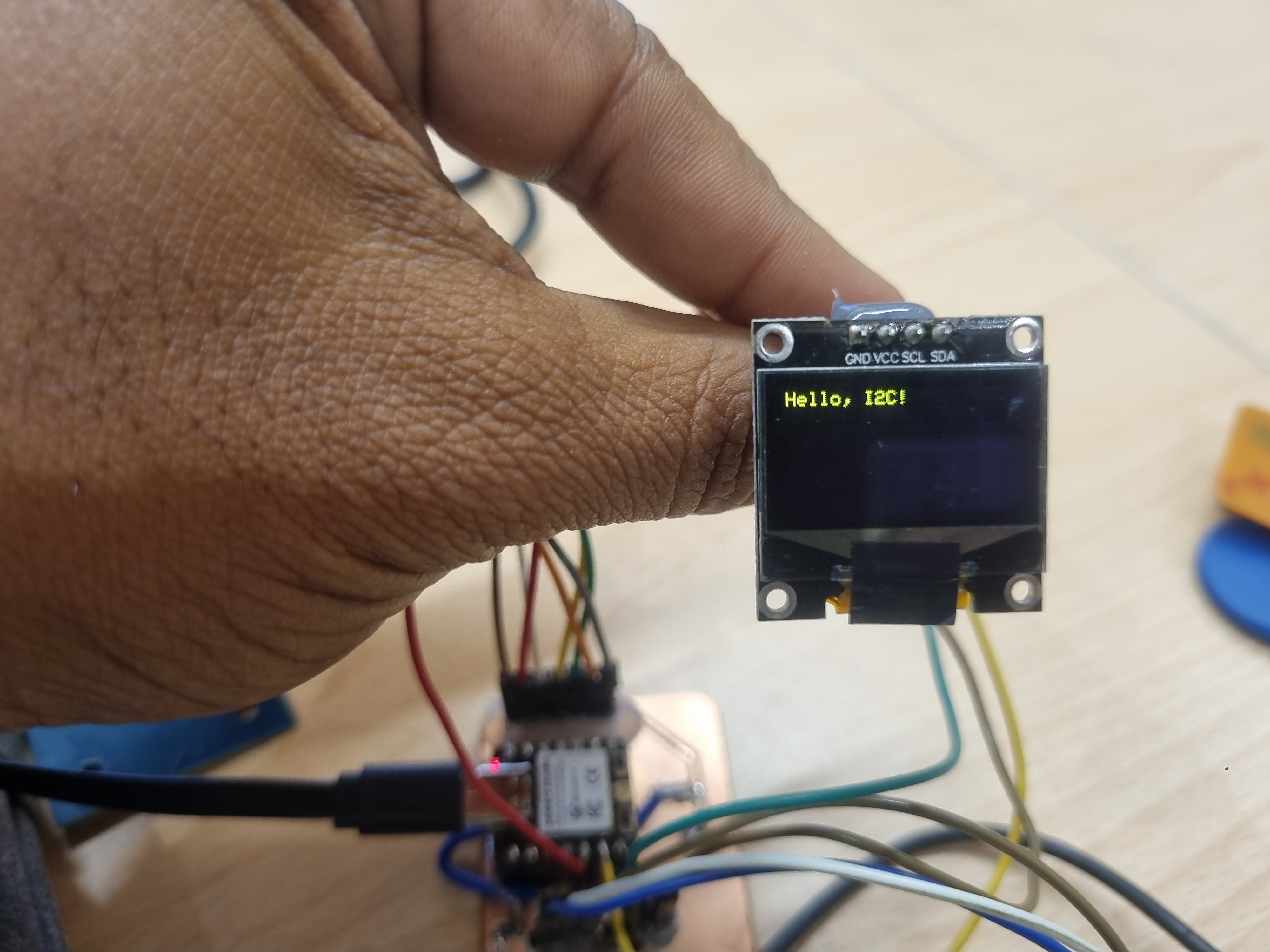
display.print("Hello, I2C!");
display.display();
}
void loop() {}
Running Test Code
Challenges and Solutions
Several challenges were encountered during this project:
1. Address Conflict
Multiple devices on the I2C bus can cause address conflicts. To avoid this, I ensured that each device had a unique address or used a multiplexer if necessary.
2. Noise and Interference
Electrical noise on the I2C lines led to communication errors. I resolved this by using shielded cables and minimizing line length.
3. Power Supply Issues
An unstable power supply caused the OLED to flicker. Adding decoupling capacitors near the OLED’s power pins resolved the issue.
Conclusion
This assignment demonstrated the successful integration of an OLED display with the ESP32-C3 using the I2C protocol. The project reinforced the importance of proper hardware design, addressing, and error handling in communication protocols. The skills and insights gained from this exercise are applicable to a wide range of IoT and embedded system projects.