Week14
Assignment: Interface and Application Programming
Individual Assignment:
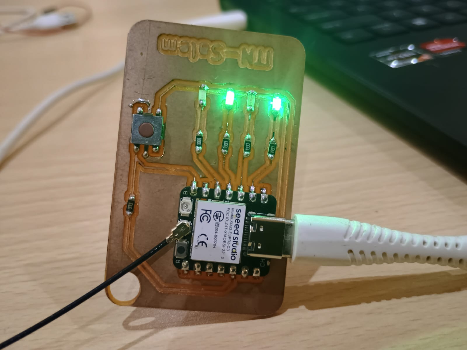
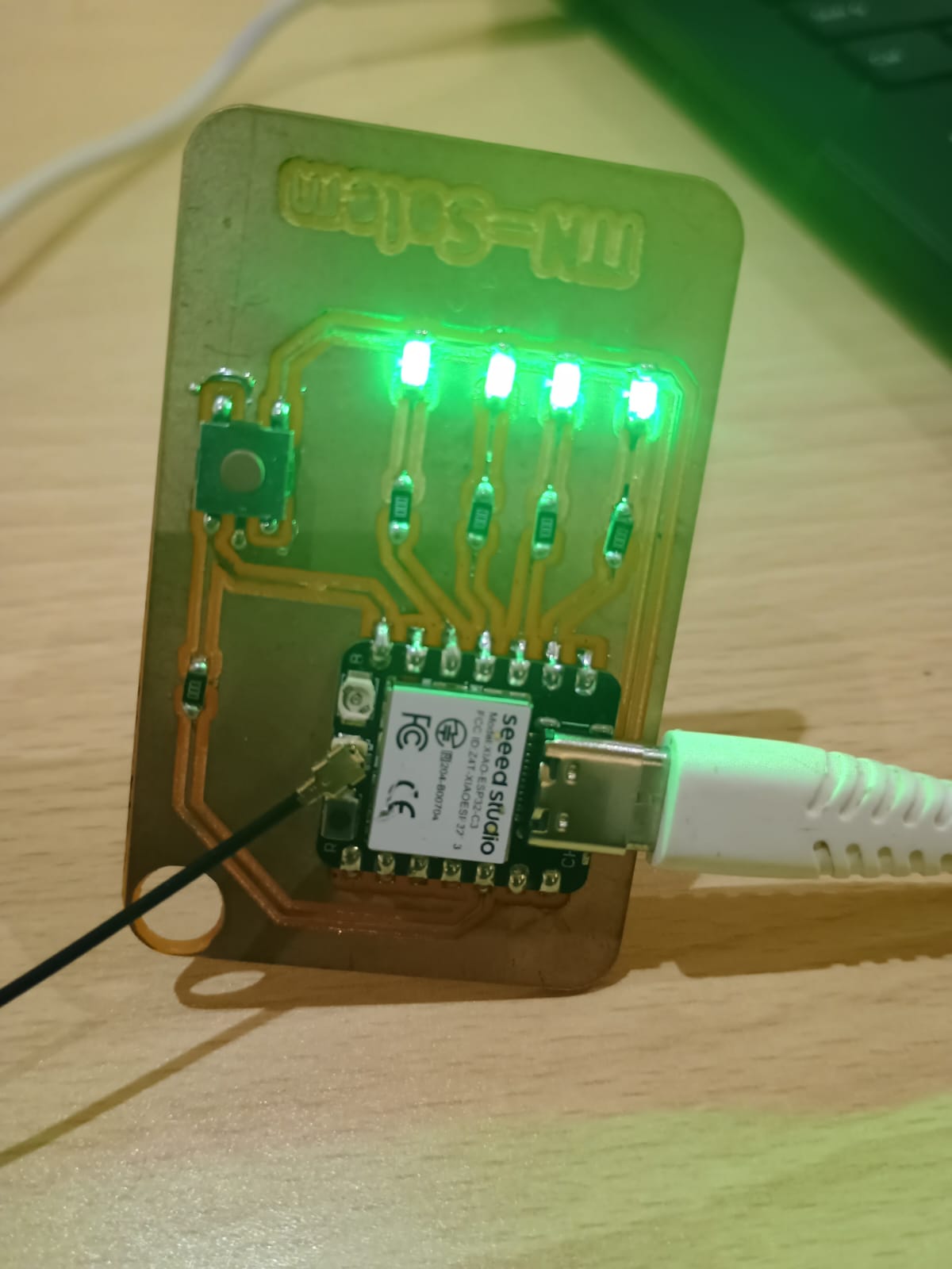
Creating a PCB with Seeed Studio XIAO ESP32-C3 and an input sensor. For this assignment accelerometer sensor is used to blink LEDs positioned to that direction.
During this assignment, I had a valuable and hands-on learning experience while developing an ESP32-C3-based LED control system. I worked with web-based wireless communication to control multiple LEDs through an HTML interface. This project gave me practical insight into Wi-Fi-based embedded networking, web server creation, and GPIO control.
I learned how to:
This improved my confidence in embedded development and gave me a clear understanding of how microcontrollers interact with the internet and control hardware in real time.
For full documentation, refer: Electronics Production Assignment
GPIO Mapping for LEDs:
LED Color | GPIO | Function |
LED1 | 3 | LED1 Control |
LED2 | 4 | LED2 Control |
LED3 | 5 | LED3 Control |
LED4 | 6 | LED4 Control |
Each GPIO was connected to an LED through a 220Ω resistor to limit current.
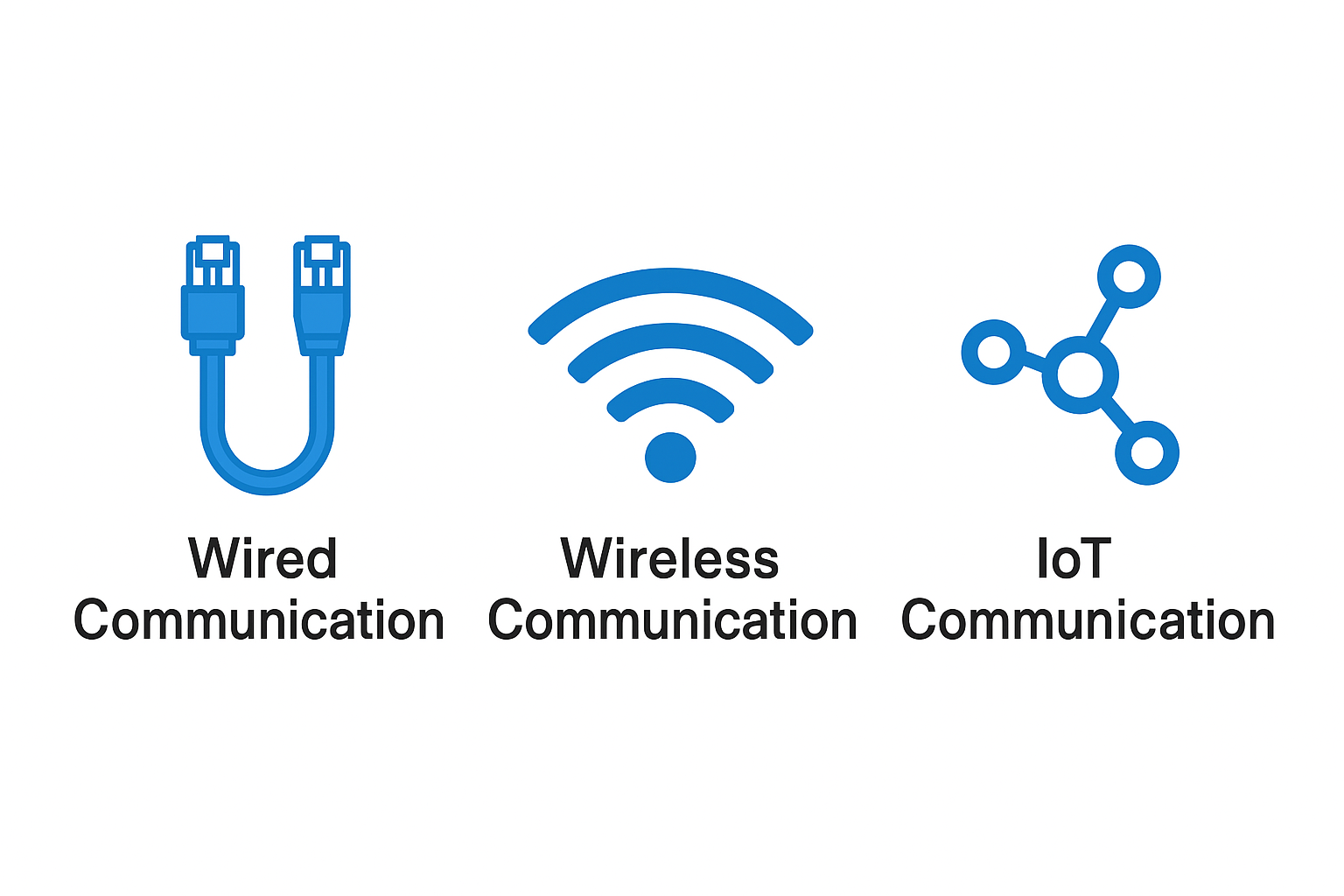
My project used Wi-Fi as the communication backbone. The ESP32-C3 connected to a local Wi-Fi network and hosted an HTTP server that users could access from any device on the same network.
Even though it’s not “network communication,” it's still digital communication:
🔌 Wired Communication
https://raw.githubusercontent.com/espressif/arduino-esp32/gh-pages/package_esp32_index.json
3. Go to Tools > Board > Board Manager, search for ESP32 and install it.
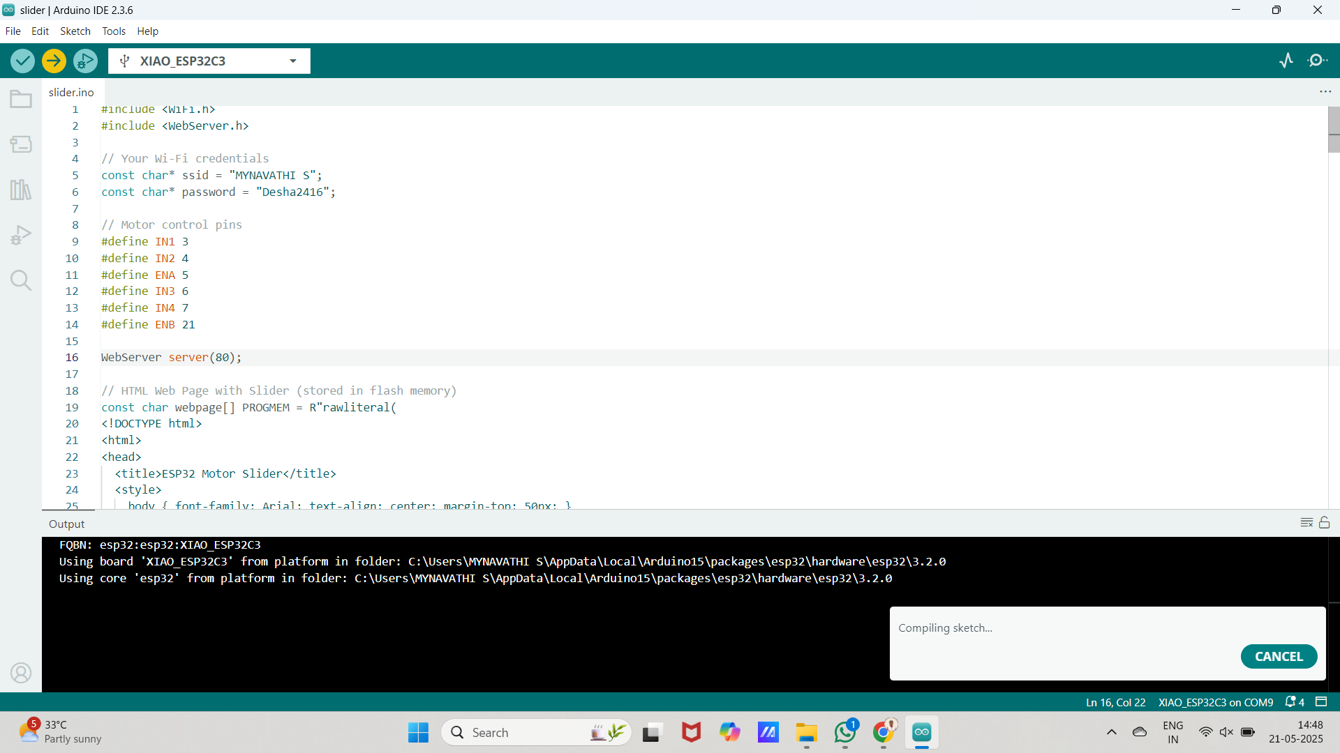
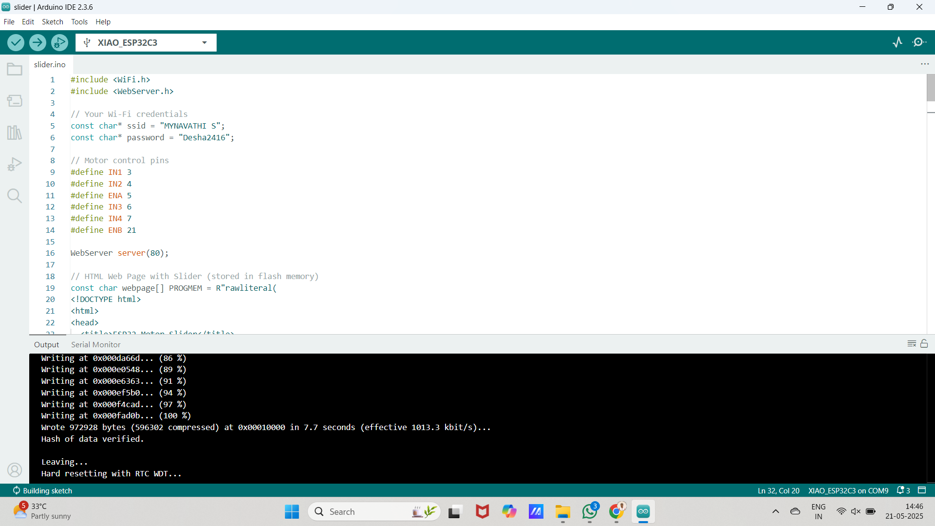
Figure 1: Code successfully verified and uploaded to the board
After writing and verifying the code, I uploaded it to the ESP32-C3 board. The compilation was successful, and the code was uploaded without any errors.
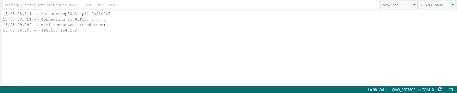
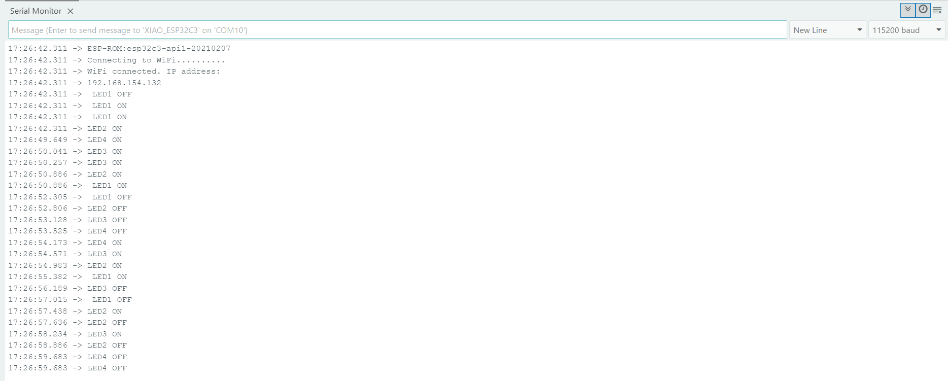
Figure 2: Device connecting to Wi-Fi as shown in the Serial Monitor
The Serial Monitor showed that the device was successfully connecting to my Wi-Fi network using the SSID and password provided in the code.
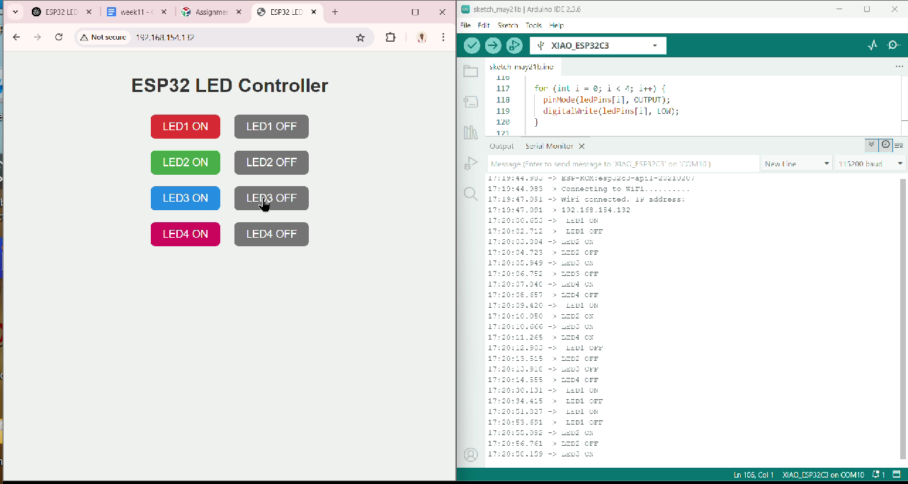
Figure 4: Real-time data monitoring and successful communication
For my individual assignment, I focused on learning wireless web-based control of hardware using ESP32-C3. I explored how to:
In addition to basic hardware handling, I learned to serve real-time UI updates via HTTP requests, a core IoT technique.
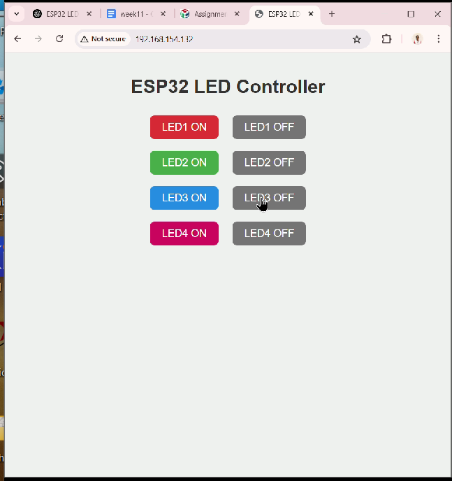
The HTML page consisted of:
Complete Arduino Code:
#include <WiFi.h>
#include <WebServer.h>
// Wi-Fi Credentials
const char* ssid = "MYNAVATHI S";
const char* password = "Desha2416";
// LED pins
const int ledPins[4] = {3, 4, 5, 6}; // GPIOs for Red, Green, Blue, Pink
WebServer server(80);
// HTML Page with JavaScript and CSS
const char MAIN_page[] PROGMEM = R"rawliteral(
<!DOCTYPE html>
<html>
<head>
<title>ESP32 LED Control</title>
<style>
body { font-family: Arial; text-align: center; margin-top: 40px; background: #f0f0f0; }
h1 { color: #333; }
button {
font-size: 18px; padding: 10px 20px; margin: 10px;
border: none; border-radius: 8px;
cursor: pointer;
color: white;
}
.red { background-color: #e53935; }
.green { background-color: #43a047; }
.blue { background-color: #1e88e5; }
.pink { background-color: #d81b60; }
.off { background-color: #757575; }
</style>
</head>
<body>
<h1>ESP32 LED Controller</h1>
<div>
<button class="red" onclick="send('red/on')">LED1 ON</button>
<button class="off" onclick="send('red/off')">LED1 OFF</button><br>
<button class="green" onclick="send('green/on')">LED2 ON</button>
<button class="off" onclick="send('green/off')">LED2 OFF</button><br>
<button class="blue" onclick="send('blue/on')">LED3 ON</button>
<button class="off" onclick="send('blue/off')">LED3 OFF</button><br>
<button class="pink" onclick="send('pink/on')">LED4 ON</button>
<button class="off" onclick="send('pink/off')">LED4 OFF</button>
</div>
<script>
function send(path) {
fetch('/' + path)
.then(response => response.text())
.then(data => console.log(data));
}
</script>
</body>
</html>
)rawliteral";
void handleRoot() {
server.send_P(200, "text/html", MAIN_page);
}
void setupRoutes() {
server.on("/", handleRoot);
server.on("/red/on", []() {
digitalWrite(ledPins[0], HIGH);
Serial.println(" LED1 ON");
server.send(200, "text/plain", "Red ON");
});
server.on("/red/off", []() {
digitalWrite(ledPins[0], LOW);
Serial.println(" LED1 OFF");
server.send(200, "text/plain", "Red OFF");
});
server.on("/green/on", []() {
digitalWrite(ledPins[1], HIGH);
Serial.println("LED2 ON");
server.send(200, "text/plain", "Green ON");
});
server.on("/green/off", []() {
digitalWrite(ledPins[1], LOW);
Serial.println("LED2 OFF");
server.send(200, "text/plain", "Green OFF");
});
server.on("/blue/on", []() {
digitalWrite(ledPins[2], HIGH);
Serial.println("LED3 ON");
server.send(200, "text/plain", "Blue ON");
});
server.on("/blue/off", []() {
digitalWrite(ledPins[2], LOW);
Serial.println("LED3 OFF");
server.send(200, "text/plain", "Blue OFF");
});
server.on("/pink/on", []() {
digitalWrite(ledPins[3], HIGH);
Serial.println("LED4 ON");
server.send(200, "text/plain", "Pink ON");
});
server.on("/pink/off", []() {
digitalWrite(ledPins[3], LOW);
Serial.println("LED4 OFF");
server.send(200, "text/plain", "Pink OFF");
});
}
void setup() {
Serial.begin(115200);
for (int i = 0; i < 4; i++) {
pinMode(ledPins[i], OUTPUT);
digitalWrite(ledPins[i], LOW);
}
WiFi.begin(ssid, password);
Serial.print("Connecting to WiFi");
while (WiFi.status() != WL_CONNECTED) {
delay(500);
Serial.print(".");
}
Serial.println("\nWiFi connected. IP address: ");
Serial.println(WiFi.localIP());
setupRoutes();
server.begin();
}
void loop() {
server.handleClient();
}
Serial Monitor Output:
When running, you should see
And for LED control via web:
This assignment helped me strengthen my knowledge in:
Video link
Working file link: LINK