***In this assignment, I have used Gemini as an experiment to see how to use ChatGPT for documentation. Major content is curated using Gemini, and it's for learning purposes.
Individual Assignment:
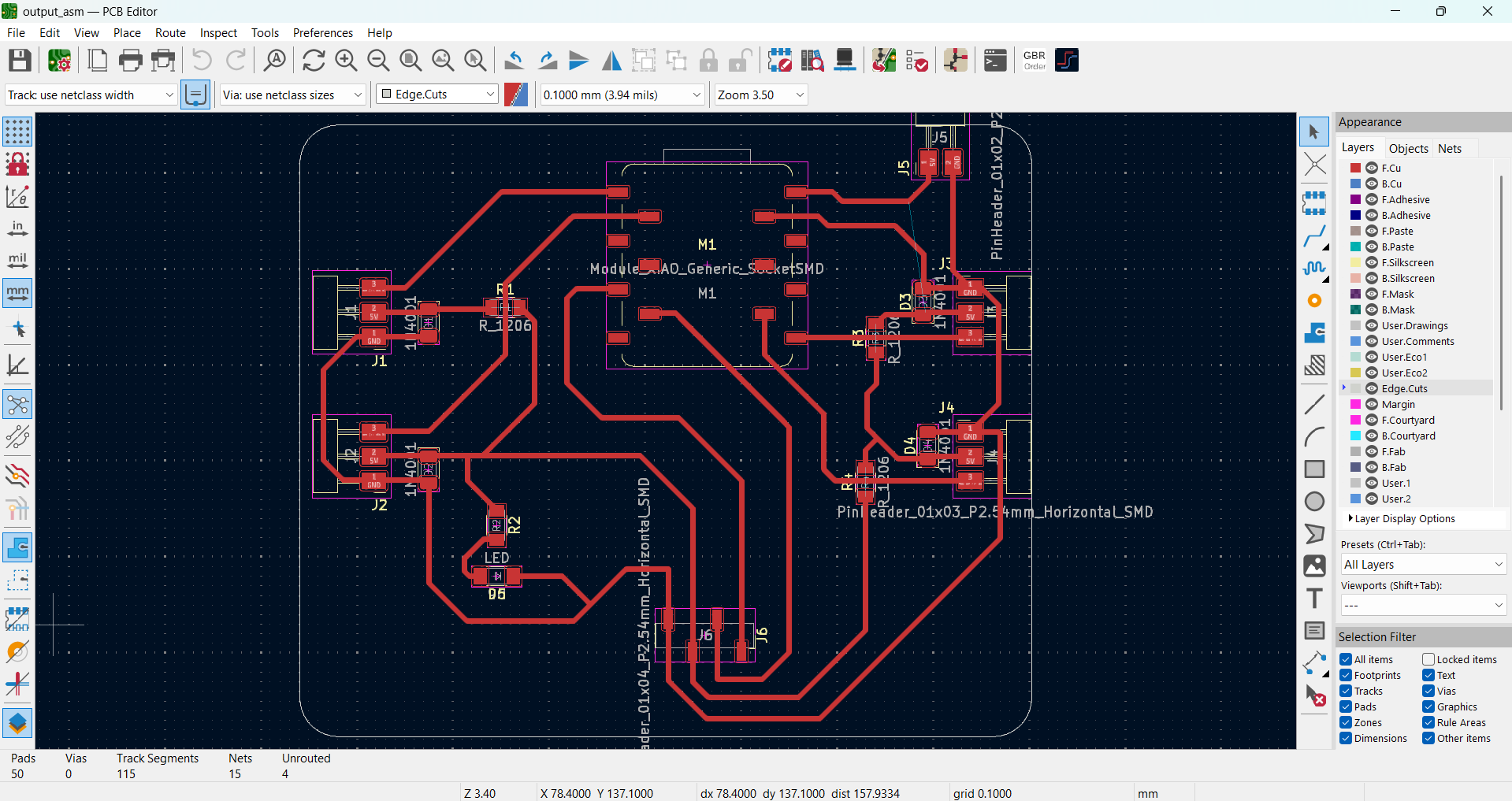
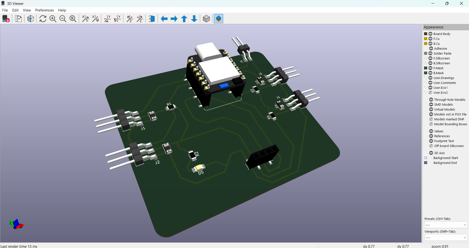
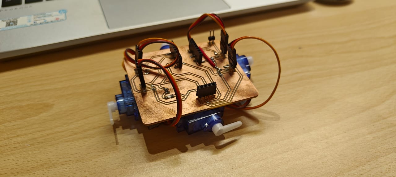
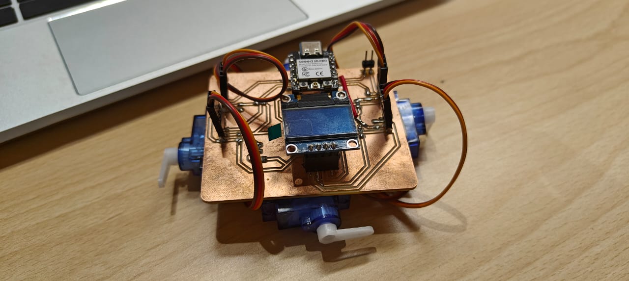
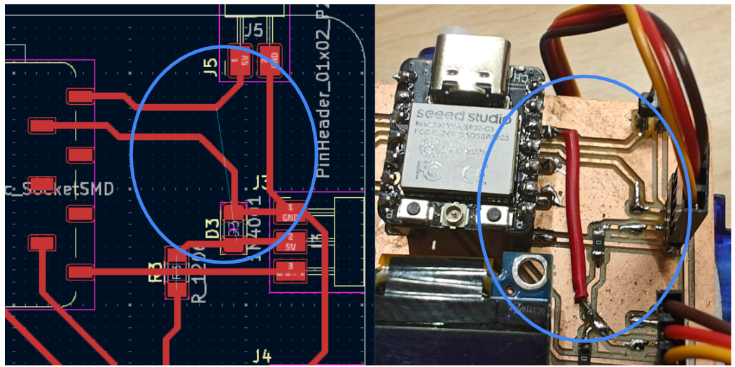
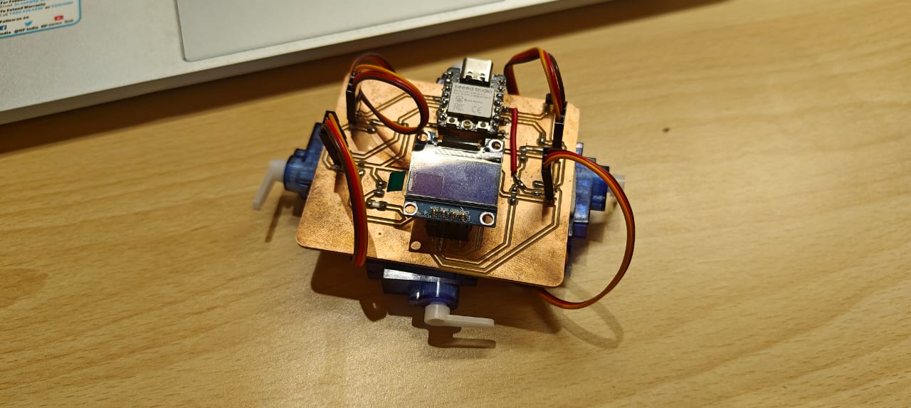
Creating a PCB with Seeed Studio XIAO ESP32-C3 and output devices. For this assignment, 4 stepper motors are connected and simulated using a program.
What are Output Devices?
Output devices receive electrical signals from a microcontroller (like the XIAO we often use in Fab Academy) and convert these signals into a different form of energy or information that humans can perceive or that can act upon the environment. Think of it as the reverse of an input device, which senses the physical world and converts it into electrical signals.
Why are Output Devices Important?
Output devices are crucial because they:
Enable Interaction: They allow our projects to communicate with users through visual feedback, sounds, or physical movements.
Perform Actions: They can drive motors, control lights, and activate other mechanisms to achieve a desired outcome.
Provide Feedback: They can indicate the status of a system, alert users to events, or display sensor readings.
Bring Ideas to Reality: They are the tangible manifestation of our digital designs, making our projects functional and engaging.
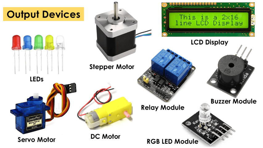
Types of Output Devices:
The world of output devices is vast and varied! Here are some common types you'll likely encounter in Fab Academy and beyond:
1. Visual Displays:
LEDs (Light Emitting Diodes): Simple yet versatile, LEDs can indicate states, create patterns, and form basic displays. Different colors and sizes offer a wide range of possibilities.
Seven-Segment Displays: Ideal for displaying numerical information and some basic characters.
LCDs (Liquid Crystal Displays): Offer more complex text and graphical displays. Character LCDs (like 16x2) are common, as are graphical LCDs with higher resolutions.
OLEDs (Organic Light Emitting Diodes): Known for their vibrant colors, high contrast, and low power consumption. They can be flexible and come in various sizes.
E-Ink Displays: Bi-stable displays that hold their image even without power, commonly found in e-readers.
2. Motors and Actuators:
DC Motors: Rotate continuously when a voltage is applied. Speed and direction can be controlled with appropriate circuitry.
Servo Motors: Offer precise angular control, moving to specific positions based on the input signal. They are commonly used in robotics and animatronics.
Stepper Motors: Rotate in discrete steps, allowing for very accurate positioning and speed control.
Solenoids: Electromagnetic devices that produce a linear motion when energized. They are used in valves, latches, and other applications requiring a push or pull.
Relays: Electrically operated switches that allow a low-power circuit to control a high-power circuit.
3. Audio Output:
Speakers: Convert electrical signals into sound waves, allowing for the generation of tones, music, and speech.
Buzzers/Piezo Elements: Produce simple tones or beeps, often used for alarms or basic feedback.
4. Thermal Output:
Heaters: Resistive elements that generate heat when current flows through them.
Thermoelectric Coolers (TECs): Can be used for both heating and cooling by utilizing the Peltier effect.
5. Other Output Devices:
Vibrating Motors: Small motors with an eccentric weight that create vibrations, often used for haptic feedback.
Laser Diodes: Emit focused beams of light, used in various applications from measurement to cutting.
Connecting Output Devices to Microcontrollers
Interfacing output devices with microcontrollers typically involves:
Digital Output Pins: These pins can be set to either HIGH (usually the microcontroller's operating voltage) or LOW (ground), allowing for simple on/off control of devices like LEDs or relays.
Analog Output (PWM - Pulse Width Modulation): By rapidly switching a digital pin on and off with varying duty cycles, we can effectively control the average power delivered to a device, allowing for dimming LEDs or controlling motor speed.
Communication Protocols: More complex output devices like LCDs or addressable LEDs often use communication protocols like I2C or SPI to receive commands and data from the microcontroller.
Driver Circuits: Many output devices, especially motors and high-power devices, require driver circuits (e.g., motor driver ICs, transistor switches) to handle the necessary current and voltage levels, protecting the microcontroller.
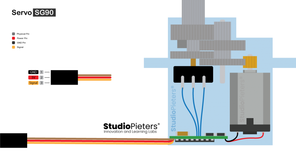
What is SG90 ?
The SG90 is a very popular and inexpensive micro servo motor widely used in hobby robotics, radio-controlled models, and DIY electronics projects. Its small size, light weight, and ease of control make it a go-to actuator for many applications where precise angular movement is required.
Here's a detailed explanation of the SG90:
Key Features and Characteristics:
Compact Size and Weight: Typically weighs around 9 grams and has dimensions of approximately 22mm x 11.8mm x 31mm. This makes it ideal for small and lightweight projects.
Operating Voltage: Generally operates between 4.8V and 6V DC. Some sources mention a wider range of 3.0V to 7.2V, but 4.8V to 6V is the common and recommended range.
Control Signal: Controlled using Pulse Width Modulation (PWM) signals. The length of the HIGH pulse determines the angular position of the servo shaft.
Rotation Angle: Most standard SG90 servos offer a rotation range of approximately 180 degrees (around 90 degrees in each direction from the center). Some variations might offer slightly different ranges.
Torque: The stall torque (the maximum torque the servo can exert when it's not moving) typically ranges from 1.2 kg-cm to 2.5 kg-cm (kilogram-centimeters) at 4.8V. The torque increases slightly at higher operating voltages. This is sufficient for many small-scale movements and light loads.
Speed: The operating speed is usually around 0.1 to 0.12 seconds per 60 degrees at 4.8V with no load. This indicates how quickly the servo can move to a new position.
Gear Type: Typically features plastic gears. While this keeps the cost and weight down, it might not be as durable as metal gears in high-stress applications. Some higher-quality or slightly more expensive micro servos might offer metal gears (like the MG90S, an upgrade to the SG90).
Three-Wire Interface: It has three wires for connection:
Red (VCC or Power): Connects to the positive power supply (typically 5V).
Brown or Black (GND or Ground): Connects to the ground of your circuit.
Yellow or Orange (Signal): Receives the PWM control signal from a microcontroller.
JR Connector: Often comes with a standard JR-style connector, which is commonly used for servo connections.
Accessories: Usually includes a set of servo horns (also called arms or linkages) of different shapes and mounting screws for attaching the servo to your project.
How it Works (PWM Control):
Video:
The SG90's position is controlled by the width of a pulse sent to its signal wire. Here's the general principle:
A typical servo control signal has a period of 20 milliseconds (50 Hz).
Within this 20ms period, a HIGH pulse with a duration ranging from 1 millisecond to 2 milliseconds is sent.
1 ms pulse: Typically corresponds to one extreme of the servo's rotation (e.g., 0 degrees).
1.5 ms pulse: Typically corresponds to the center position (e.g., 90 degrees for a 180-degree servo).
2 ms pulse: Typically corresponds to the other extreme of the servo's rotation (e.g., 180 degrees).
By varying the width of this HIGH pulse (between 1ms and 2ms), you can precisely control the angular position of the servo shaft.
Microcontrollers like the Arduino have built-in libraries (like the Servo library) that simplify the generation of these precise PWM signals, allowing you to easily command the SG90 to move to specific angles.
Video Link Programing
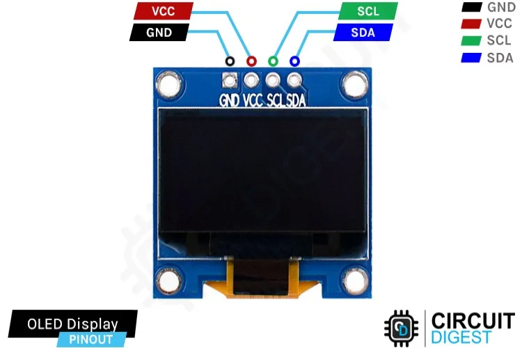
What is an OLED Display?
OLED stands for Organic Light-Emitting Diode. Unlike traditional LCDs (Liquid Crystal Displays) that require a separate backlight to illuminate their pixels, each pixel in an OLED display is an individual light-emitting diode. This self-emissive property gives OLEDs several key advantages:
True Blacks: When an OLED pixel is turned off, it emits no light, resulting in a perfect, inky black. This creates incredibly high contrast ratios.
Vibrant Colors: OLEDs generally produce more vibrant and saturated colors.
Wide Viewing Angles: The light is emitted directly from the pixels, so the image remains clear and colors don't shift even when viewed from extreme angles.
Faster Response Times: Pixels can turn on and off much faster than LCDs, leading to smoother motion and less blurring.
Thinner and More Flexible: Without a backlight, OLED panels can be made extremely thin and even flexible (though most hobbyist modules are rigid).
Lower Power Consumption (for dark content): Since only the lit pixels draw power, displaying mostly black content (common in monochrome displays) can significantly reduce power consumption compared to a backlit LCD.
What is I2C Communication?
I2C (Inter-Integrated Circuit), also known as TWI (Two-Wire Interface), is a synchronous, multi-master/multi-slave serial communication protocol. It's widely used for short-distance, intra-board communication between integrated circuits.
Key features of I2C:
Two Wires: It only requires two wires for communication:
SDA (Serial Data Line): Carries the actual data.
SCL (Serial Clock Line): Provides the clock signal to synchronize data transfer.
Master-Slave Architecture: Typically, a microcontroller acts as the "master," initiating and controlling communication, while the OLED display acts as a "slave."
Addressing: Each I2C device on the bus has a unique 7-bit (or sometimes 10-bit) address. The master sends this address to select which slave device it wants to communicate with. This allows multiple I2C devices to share the same two SDA and SCL lines. Common addresses for SSD1306 OLEDs are 0x3C or 0x3D.
Simplicity: With only two wires, I2C significantly simplifies wiring compared to parallel interfaces or even SPI (which typically requires more wires for single-slave setups).
Speed: I2C is generally considered a "low-speed" protocol, suitable for communicating with peripherals like displays, sensors, and EEPROMs, but not for high-bandwidth data transfer (like video streams).
I2C OLED Display Modules (e.g., SSD1306)
The most common I2C OLED displays for hobbyists are based on the SSD1306 driver IC. These modules come in various sizes and resolutions, with 0.96-inch 128x64 pixel and 0.91-inch 128x32 pixel monochrome (usually white or blue) displays being the most popular.
How it Works (Simplified):
Module Components: An I2C OLED display module consists of:
The OLED panel itself (the actual display area with pixels).
A driver IC (like the SSD1306) that manages the individual pixels and handles the I2C communication. This chip contains an internal Graphics Display Data RAM (GDDRAM) that stores the pixel data.
Connection: You connect the module to your microcontroller using just four pins:
VCC: Power supply (usually 3.3V or 5V, check module specifics).
GND: Ground.
SDA: Connects to the microcontroller's SDA pin.
SCL: Connects to the microcontroller's SCL pin.
Microcontroller Interaction:
Your microcontroller (e.g., Arduino, ESP32, Raspberry Pi Pico) initializes its I2C communication interface.
It then uses a library (like Adafruit's GFX and SSD1306 libraries) to send commands and pixel data to the OLED's driver IC over the I2C bus.
The driver IC receives this data, stores it in its GDDRAM, and then translates it into the electrical signals needed to turn individual OLED pixels on or off, creating the desired image or text on the screen.
When you want to update the display, you typically write to an internal buffer on the microcontroller and then issue a command to "display" or "draw" that buffer to the OLED.
Advantages of I2C OLED Displays:
Minimal Pin Count: Only 2 data pins (SDA, SCL) plus power and ground are needed, freeing up valuable GPIO pins on your microcontroller for other sensors or actuators.
Easy Wiring: Simple 4-wire connection makes setup quick and reduces complexity.
Daisy-Chaining (with unique addresses): You can connect multiple I2C devices (including multiple OLEDs, if they have different addresses or you use an I2C multiplexer) to the same two I2C lines.
Excellent Visual Quality: Due to OLED technology, you get high contrast, true blacks, and wide viewing angles.
Low Power Consumption: Especially when displaying mostly black content, they are very energy-efficient.
Compact Size: Ideal for projects with limited space.
Readily Available and Affordable: These modules are very common and inexpensive.
Assignment Output Devices
Objective: To connect four SG90 micro servo motors to a Seeed Studio XIAO ESP32C3 microcontroller and control their movements using a programmed sequence or user input.
1. Components Required:
Seeed Studio XIAO ESP32C3: The brain of your project. Its small form factor, ESP32-C3 chip (with Wi-Fi/BLE), and sufficient GPIO pins make it ideal.
SG90 Micro Servo Motors (x4): Your output devices. These will provide the controlled angular motion.
Breadboard: For prototyping and making connections.
Jumper Wires (Male-Male, Male-Female): To connect components on the breadboard and to the XIAO.
External Power Supply (5V, minimum 2A recommended):CRITICAL! While the XIAO can power one small servo for testing, four servos will draw significant current, potentially damaging the XIAO or causing erratic behavior. A separate 5V power supply (e.g., a dedicated 5V power adapter, a UBEC from an RC hobby shop, or a good quality power bank) is essential.
Power Barrel Jack Adapter (if using a standard power adapter): To connect your power supply to the breadboard.
Optional (but recommended for safety):
Capacitor (e.g., 100uF - 470uF, 6.3V or higher): To smooth out power fluctuations when the servos move. Connect across the 5V and GND lines of your servo power rail on the breadboard.
2. Understanding the Seeed Studio XIAO ESP32C3:
The XIAO ESP32C3 has several GPIO pins, many of which can generate PWM signals. This is perfect for controlling multiple servos. Look at the pinout diagram for your specific XIAO ESP32C3 board. You'll primarily be using the digital pins capable of PWM.
Power: The XIAO ESP32C3 typically operates at 3.3V logic. However, its 5V pin can be used to power small peripherals, and it's robust enough for the signal lines from the SG90s.
PWM Pins: Identify at least four digital pins on your XIAO ESP32C3 that support PWM output. For the ESP32-C3, almost all GPIO pins can be used for PWM. Common choices might be D0, D1, D2, D3, D4, D5, D6, D7, D8, D9, D10. We'll pick four distinct ones.
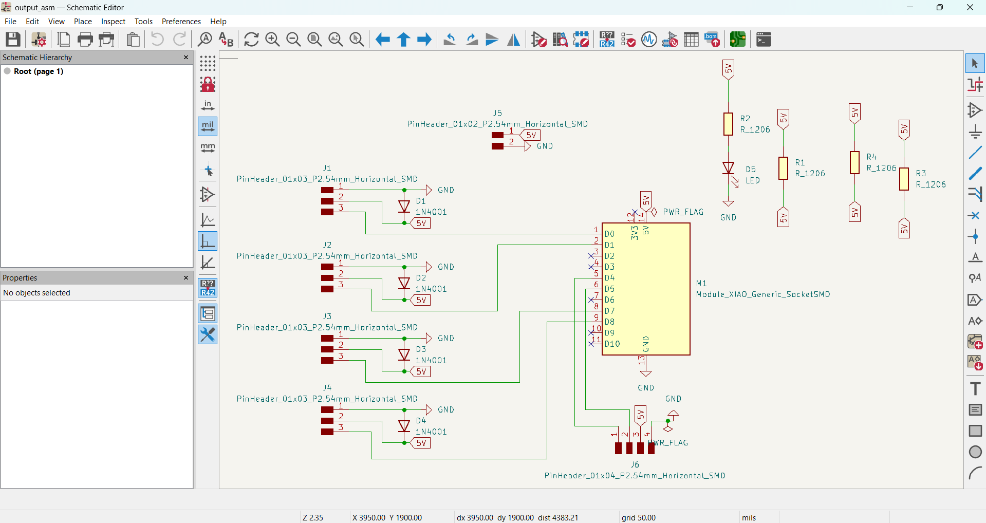
3. Wiring Diagram and Connections:
Safety First: Disconnect all power before making or changing connections.
Prepare the Power Rail on Breadboard:
Connect the positive (+) output of your external 5V power supply to the red power rail on your breadboard.
Connect the negative (-) output (GND) of your external 5V power supply to the blue ground rail on your breadboard.
Add Capacitor (Optional but Recommended): Connect the positive lead of the capacitor to the 5V rail and the negative lead to the GND rail.
Crucial: Connect XIAO's GND to Servo Power GND: Run a jumper wire from one of the GND pins on your Seeed Studio XIAO ESP32C3 to the blue ground rail on your breadboard. This creates a common ground for both the microcontroller and the servos, which is absolutely essential for communication.
Connect Each SG90 Servo (x4):
Servo 1:
Brown/Black Wire (GND): Connect to the blue ground rail on your breadboard.
Red Wire (VCC): Connect to the red power rail (5V) on your breadboard.
Yellow/Orange Wire (Signal): Connect to a chosen PWM-capable digital pin on your XIAO ESP32C3 (e.g., D0).
Servo 2:
Brown/Black Wire (GND): Connect to the blue ground rail on your breadboard.
Red Wire (VCC): Connect to the red power rail (5V) on your breadboard.
Yellow/Orange Wire (Signal): Connect to another chosen PWM-capable digital pin on your XIAO ESP32C3 (e.g., D1).
Servo 3:
Brown/Black Wire (GND): Connect to the blue ground rail on your breadboard.
Red Wire (VCC): Connect to the red power rail (5V) on your breadboard.
Yellow/Orange Wire (Signal): Connect to another chosen PWM-capable digital pin on your XIAO ESP32C3 (e.g., D2).
Servo 4:
Brown/Black Wire (GND): Connect to the blue ground rail on your breadboard.
Red Wire (VCC): Connect to the red power rail (5V) on your breadboard.
Yellow/Orange Wire (Signal): Connect to another chosen PWM-capable digital pin on your XIAO ESP32C3 (e.g., D3).
Install Arduino IDE: If you haven't already, download and install the Arduino IDE.
Add ESP32 Boards Manager:
Go to File > Preferences.
In "Additional Boards Manager URLs," add: https://raw.githubusercontent.com/espressif/arduino-esp32/gh-pages/package_esp32_index.json
Go to Tools > Board > Boards Manager...
Search for "esp32" and install the "esp32 by Espressif Systems" package.
Select XIAO ESP32C3 Board:
Go to Tools > Board > ESP32 Arduino > Seeed Studio XIAO ESP32C3.
Install Servo Library:
Go to Sketch > Include Library > Manage Libraries...
Search for "Servo" and install the "ESP32Servo" library (make sure it's the one compatible with ESP32). This library simplifies controlling servos with ESP32 boards.
5. Programming the XIAO ESP32C3:
Here's a sample Arduino sketch that demonstrates controlling four servos. You can adapt the angles and delays to create your desired movements.