Week09
Assignment: Input Devices
Software used: KiCAD
Individual Assignment:
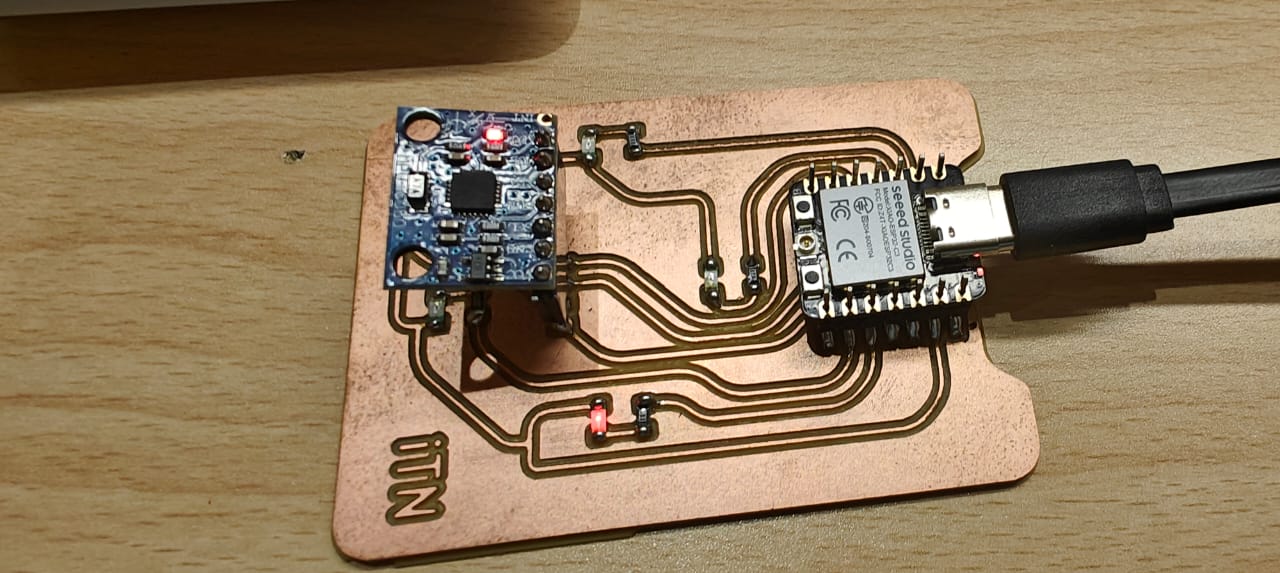
Creating a PCB with Seeed Studio XIAO ESP32-C3 and an input sensor. For this assignment accelerometer sensor is used to blink LEDs positioned to that direction.
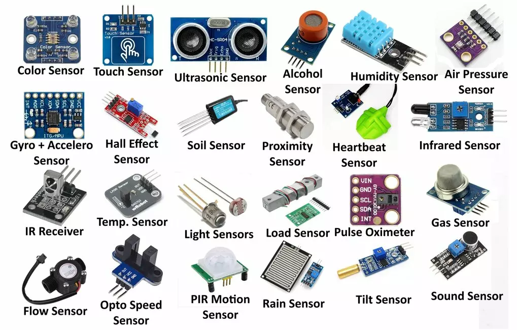
What are Sensor ?
A sensor is a device that detects and responds to a physical stimulus (like heat, light, sound, pressure, magnetism, or motion) and converts it into an electrical signal that can be measured or used to operate a control system. Essentially, it acts as an interface between the physical world and electronic systems.
Here's a breakdown of how sensors generally work:
Think of everyday examples:
Types of sensors
Image link : https://hackatronic.com/what-is-a-sensor-types-of-sensors-classification-applications/
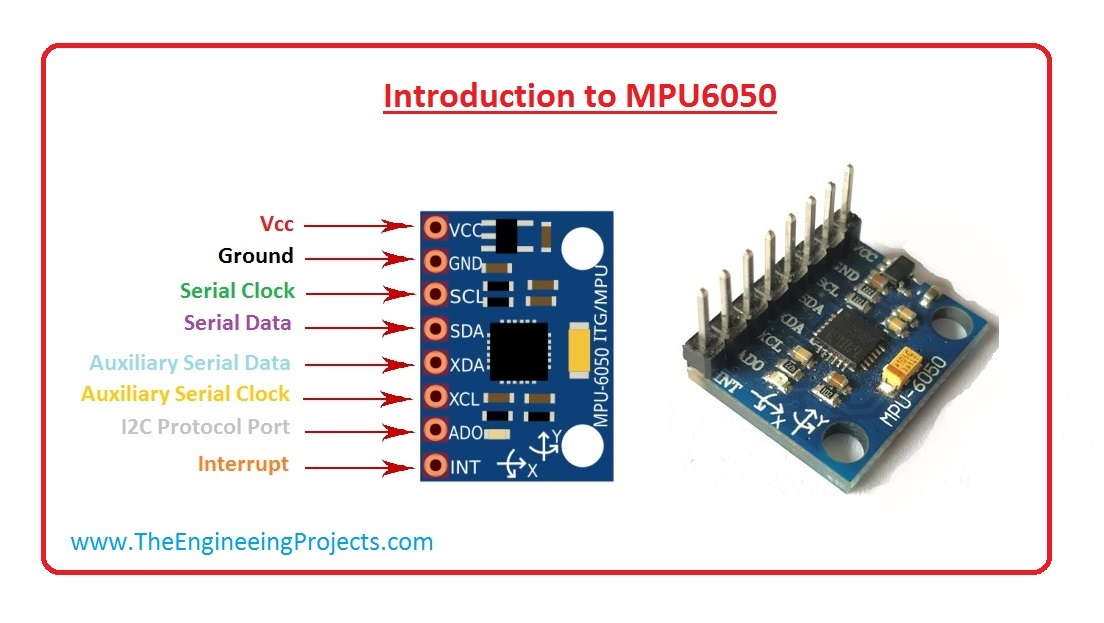
What is a MPU6050 ?
The MPU6050 is a popular and cost-effective 6-axis Inertial Measurement Unit (IMU). It integrates two key sensors on a single chip:
Key Features and Specifications of the MPU6050:
Applications of the MPU6050:
The MPU6050 is widely used in various applications that require motion sensing, including:
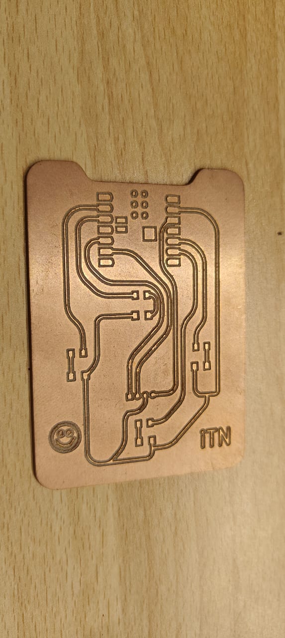
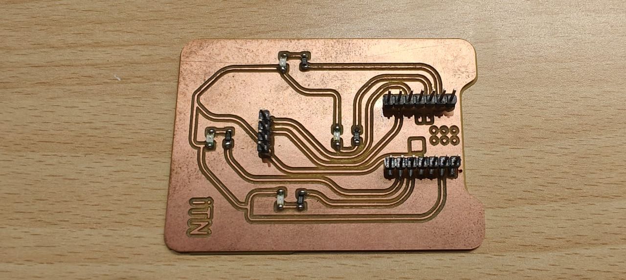
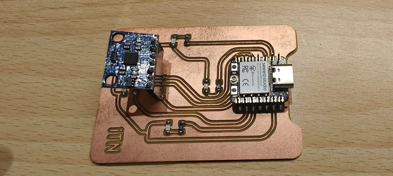
Assignment PCB Design :
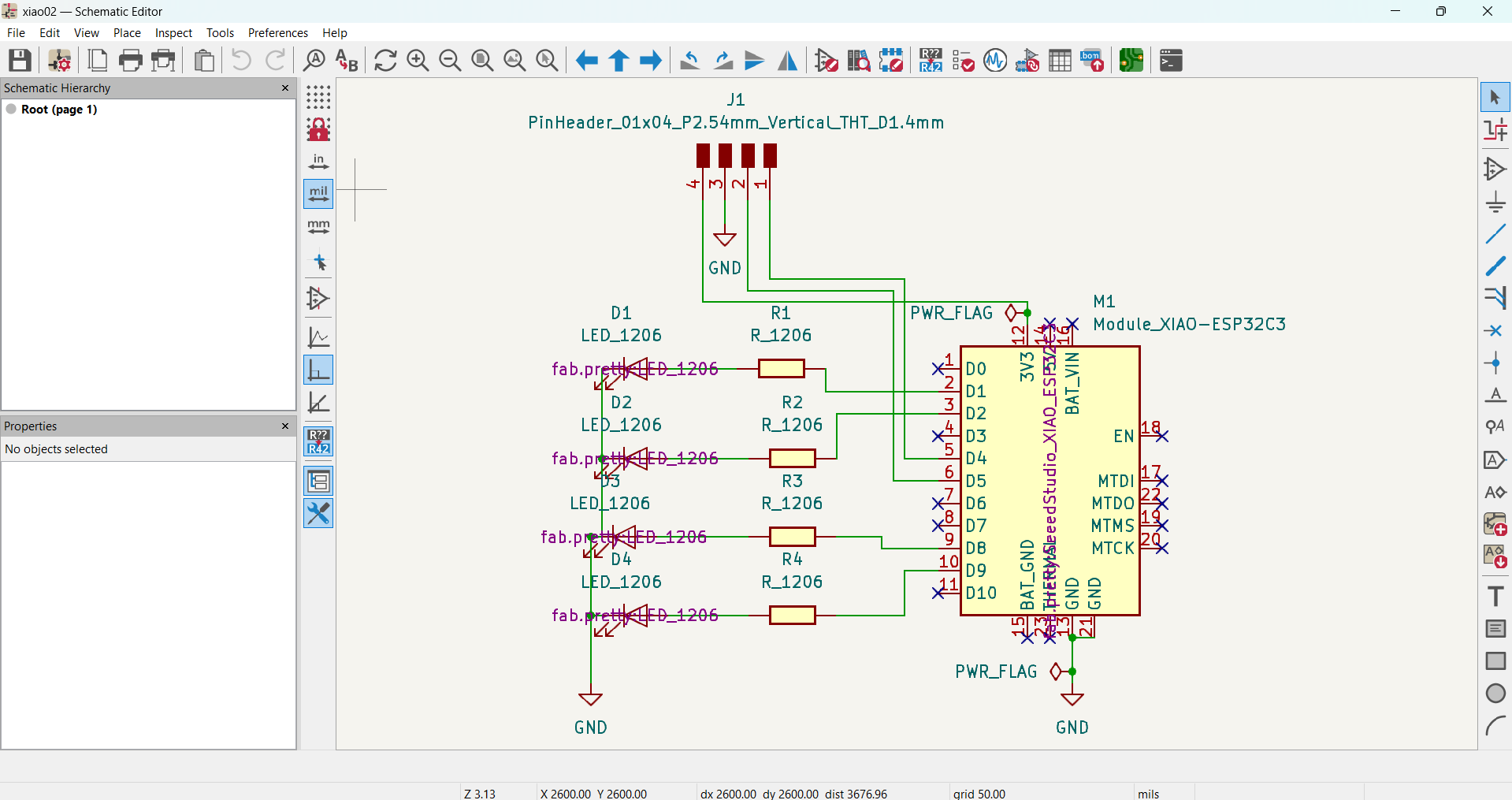
For this input assignment, a PCB is designed with XIAO c3, 4 LEDs + resistor, and MPU6050 to show the direction of the PCB's tilt.
Schematics for the circuit |
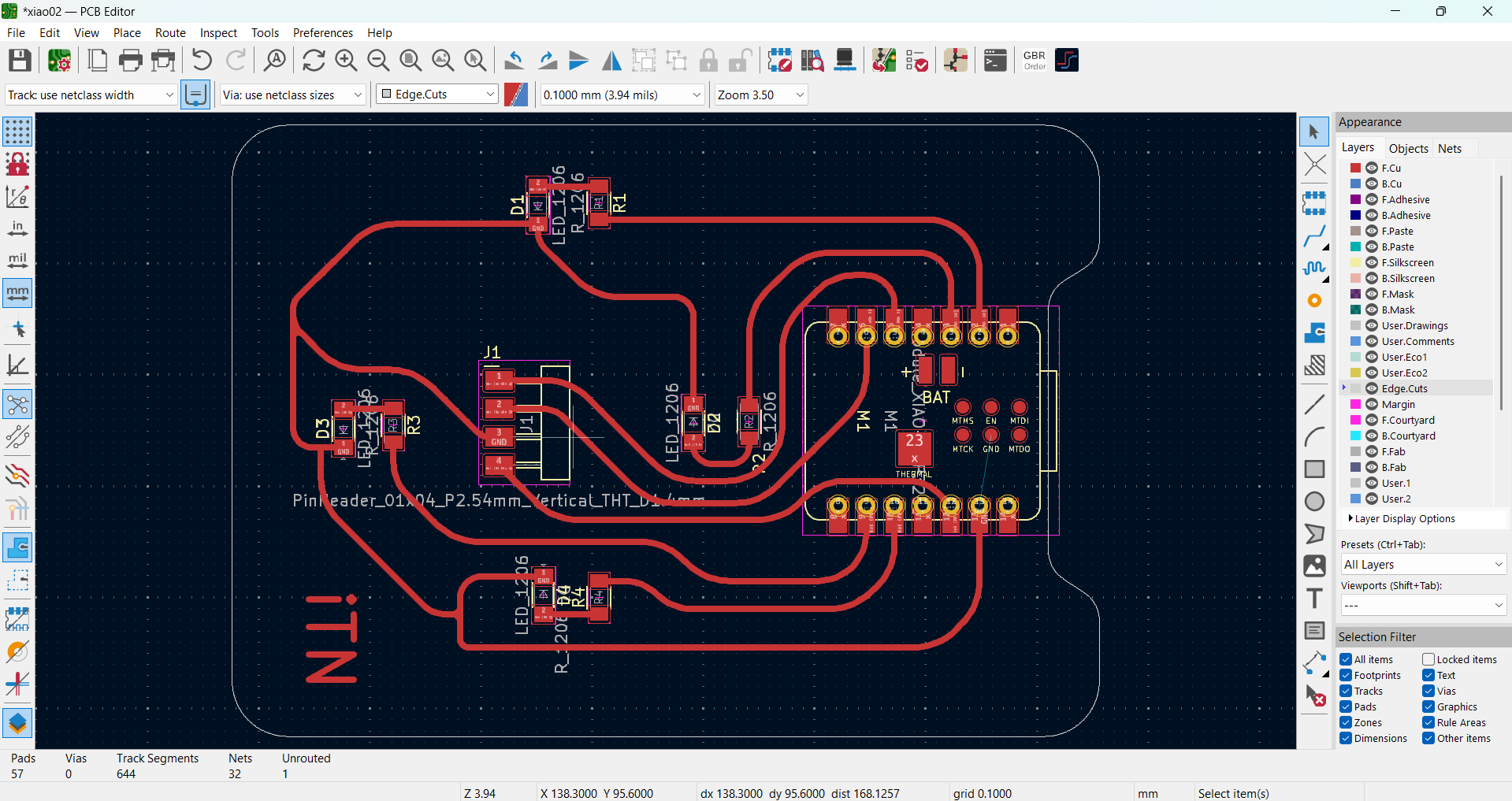
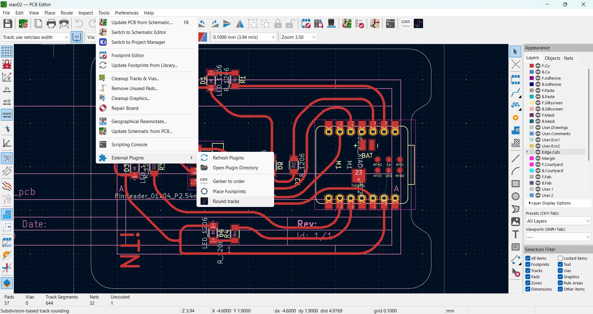
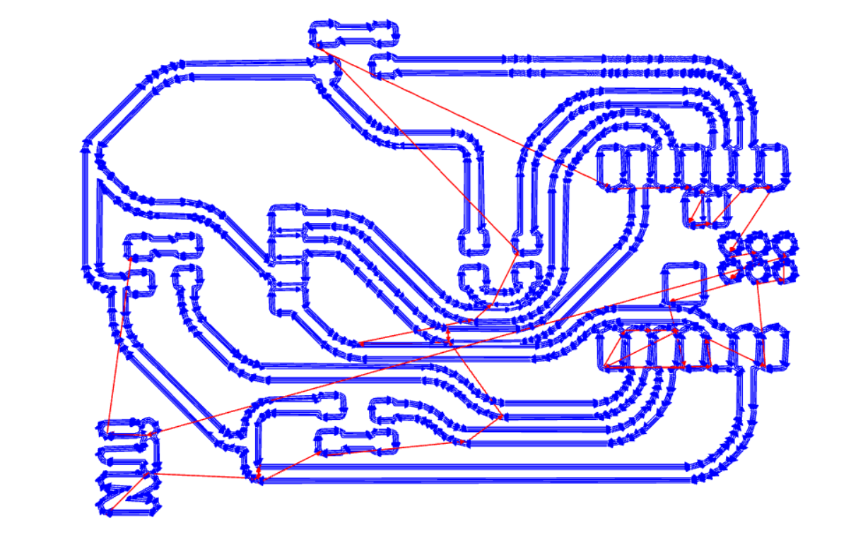
PCB design with components lined up. I have used a plug-in “Round Track” to convert all straight line tracks into filleted trackes |
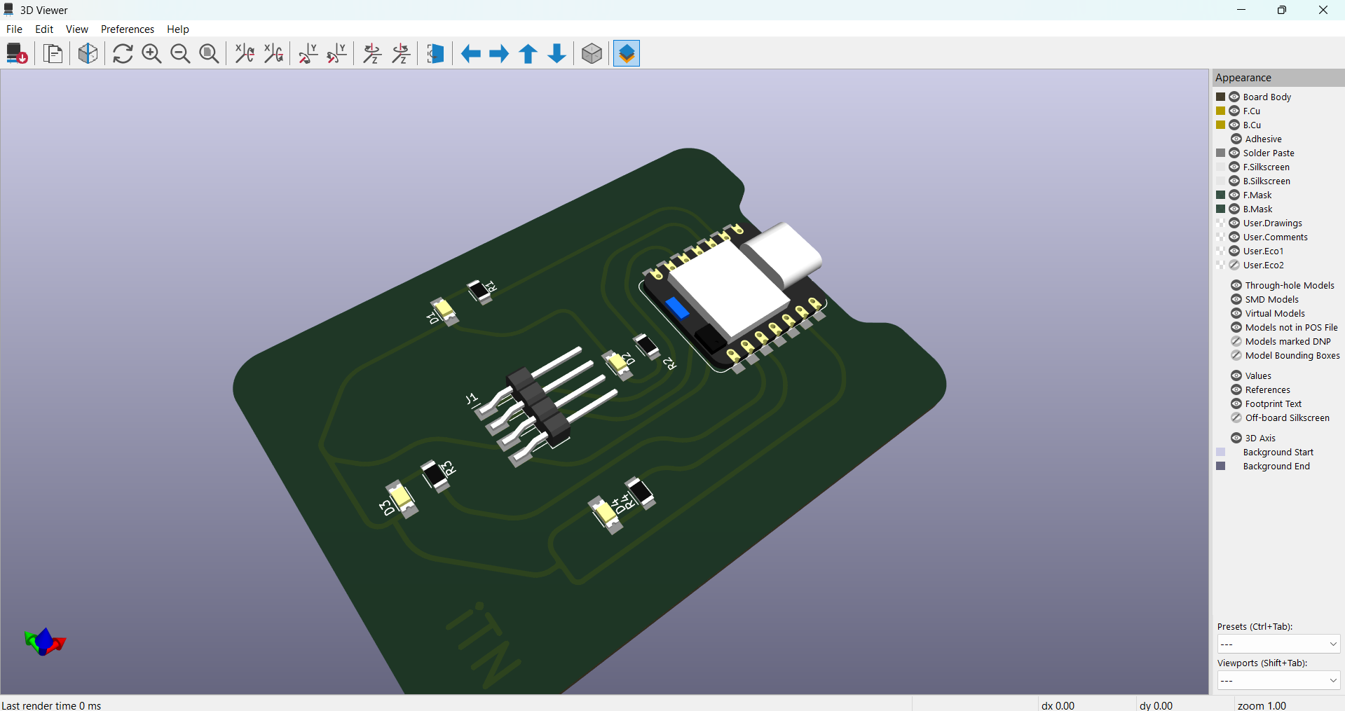
3D View of the PCB design with components. |
Program : #include <Wire.h> #define Xreg 0x3B #define Yreg 0x3D const int MPU_Addr = 0x68; int16_t accX, accY; int16_t xOffset = 0, yOffset = 0; //Front - D8, Left - D9, Right - D1, Back - D2 const int ledPins[4] = {D8, D1, D2, D9}; int readAxis(uint8_t reg) { Wire.beginTransmission(MPU_Addr); Wire.write(reg); Wire.endTransmission(false); Wire.requestFrom(MPU_Addr, 2, true); return (Wire.read() << 8) | Wire.read(); } int getDirection(int x, int y) { if (y < -1000) return 3; else if (x < -1000) return 0; else if (y > 1000) return 1; else if (x > 1000) return 2; else return -1; } void showDirection(int direction) { for(int i = 0; i < 4; i++) { digitalWrite(ledPins[i], (i == direction) ? HIGH : LOW); } } void setup() { Wire.begin(D4, D5, 10000); // SDA, SCL Serial.begin(115200); for(int i = 0; i < 4; i++) { pinMode(ledPins[i], OUTPUT); digitalWrite(ledPins[i], LOW); } // Wake MPU Wire.beginTransmission(MPU_Addr); Wire.write(0x6B); Wire.write(0); Wire.endTransmission(true); delay(1000); xOffset = readAxis(Xreg); yOffset = readAxis(Yreg); Serial.printf("xOffset : %d, yOffset : %d\n",xOffset,yOffset); } void loop() { accX = readAxis(Xreg); accY = readAxis(Yreg); int direction = getDirection(accX - xOffset, accY - yOffset); showDirection(direction); Serial.printf("accX: %d, accY: %d, direction: %d\n", accX - xOffset, accY - yOffset, direction); delay(1000); } |
Video Link
Working Files Link: LINK