Week08
Assignment: Electronics Production
Software used: KiCAD
Individual Assignment:
Creating a PCB with Seeed Studio XIAO ESP32-C3 and SMD LEDs. To create a blink program and control the blinking in the PCB.
Machine Used:
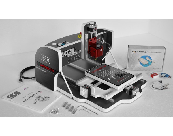
For milling the PCB we are using Wegstr CNC machine.
Machine Specification
Milling Workspace | 140x200x40 mm |
One Step of the stepper motor | 0.004 mm |
Machine Dimension | 380x460x290 mm |
Spindle | Brushless Motor |
Diameter of the spindle | 3.175 mm |
PCB Level | Auto Level |
Connectivity | USB |
Repeatability | 0.02 mm |
Machine weight | 7 kg |
Max. Speed | 170x170x170 |
Max. Height of workpiece | 40mm |
Spindle Speed | 11,000 rpm |
imagesep from Wegstr
Electronics Designing Process
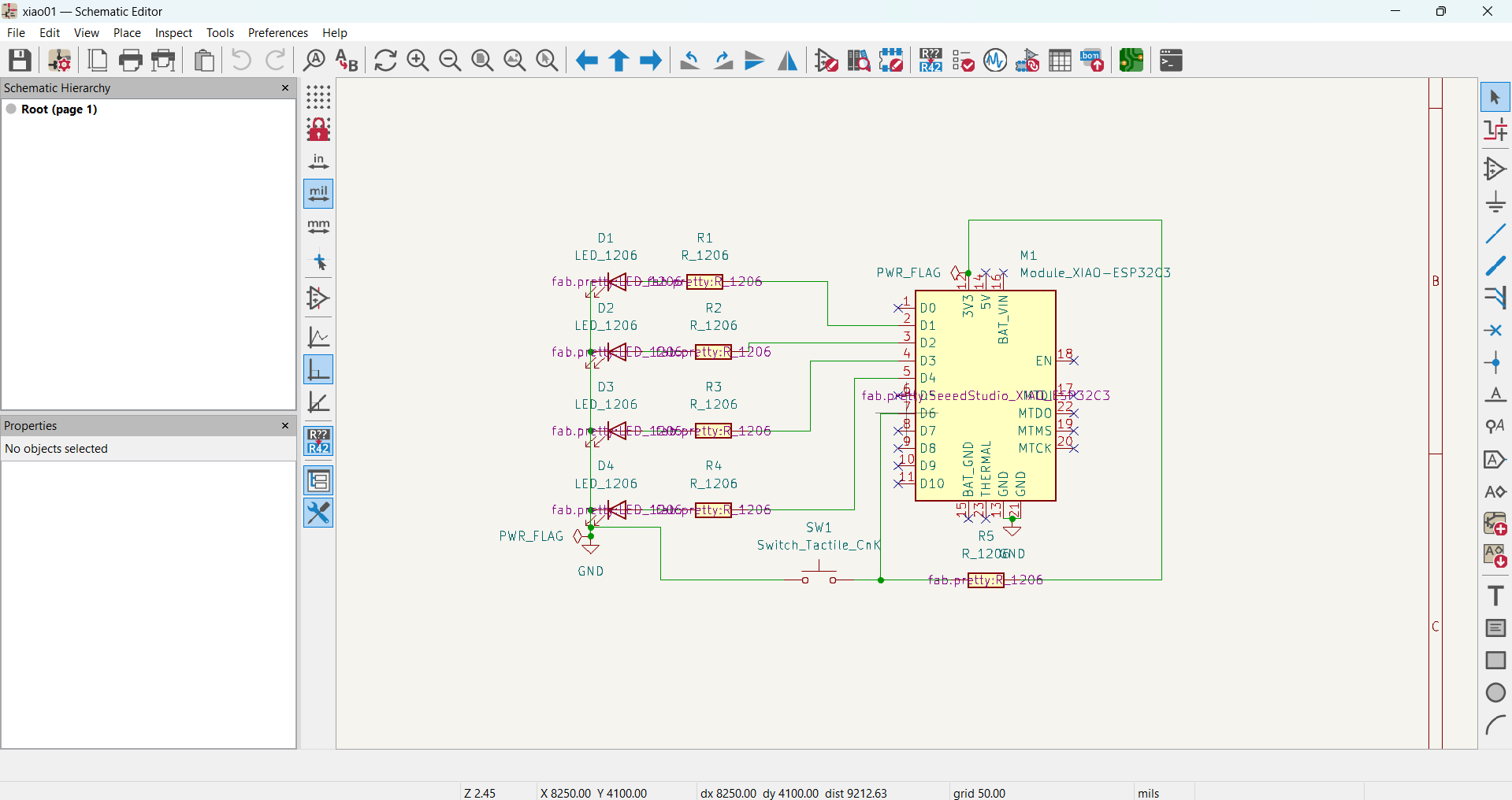
Schematic design of the PCB circuit, with XIAO, 4 LEDs & Capacitors, and a Push button |
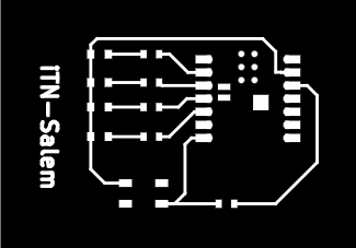
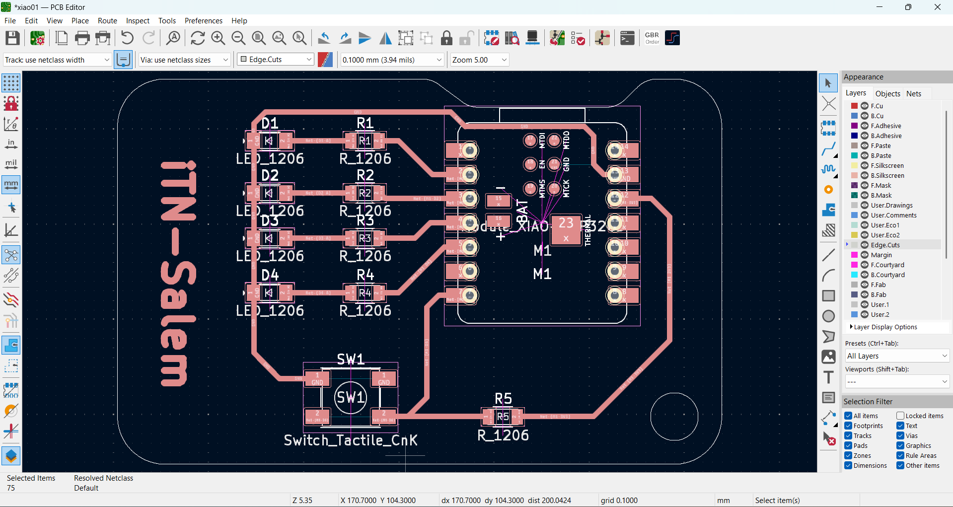
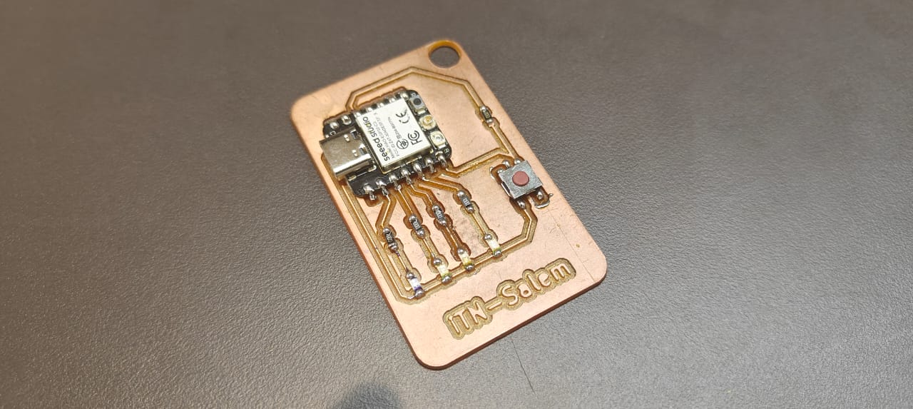
PCB Layout with tracks. Here I have added iTN-Salem, and a small key chain hole |
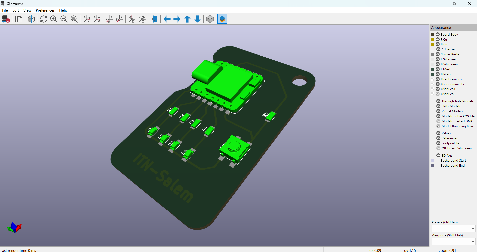
3D view of the PCB, which resembles the expected output |
Downloaded the SVG imagesep of the Track and Edge cut. |
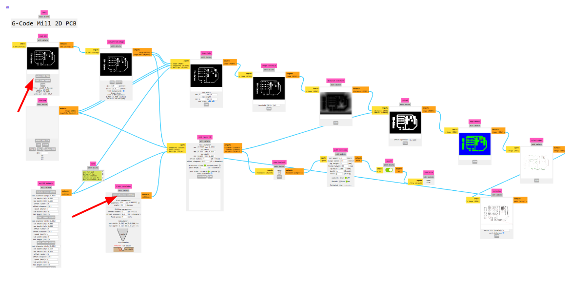
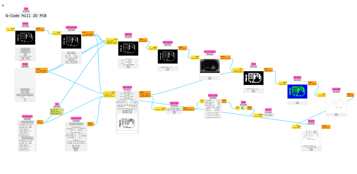
G-Code Generated using Mods:
Image from gitlab.fabcloud.org repository
Mods CE is a modular cross-platform tool for Fablabs. It is based on independent but interrelated modules. Mods could potentially be used for CAD, CAM, machine control, automation, react to physical models, and much more. I am very much interested in contributing more to community development.
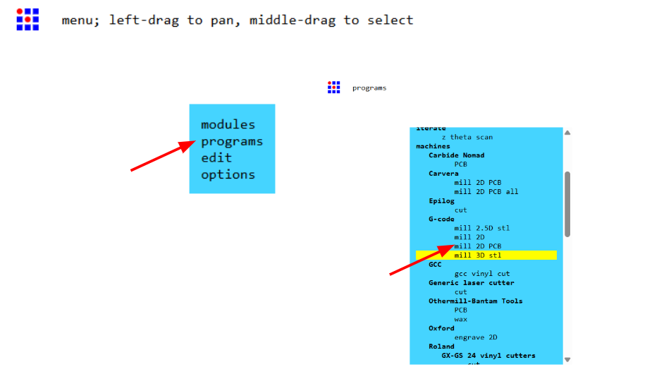
Opening page - www.modsprojecy.org . Right click for options and select programs. Under G-Code select - mill 3d PCB |
Select option “Select SVG” and pick the SVG image generated using KiCAD. |
V-Bit Calculator Select the tip diameter and offset number to 4 and click send calculation. In Mill raster 2D check is the offset value is 4, and click calculate. |
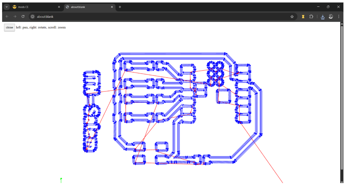
This is the toolpath generated and the numerical codes will be downloaded in the respective folder |
You can repeat the same process for the edge cut file. |
PCB Milling Process :
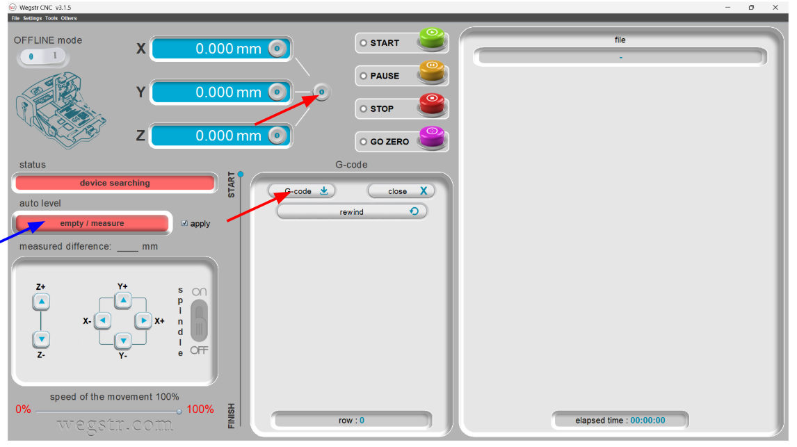
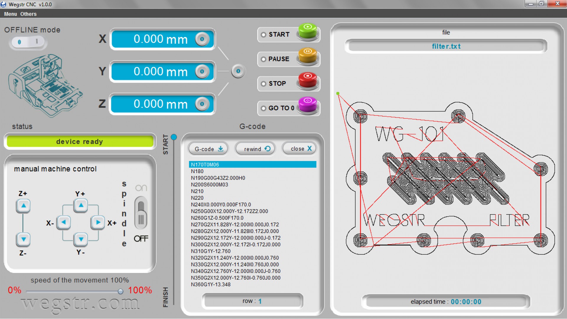
Wegstr CNC is a simple UI/UX design. First, we have to set the origin and the reset the zero. Load the G-Code and the next step is to measure the auto leveling of the bed were the PCB is placed. |
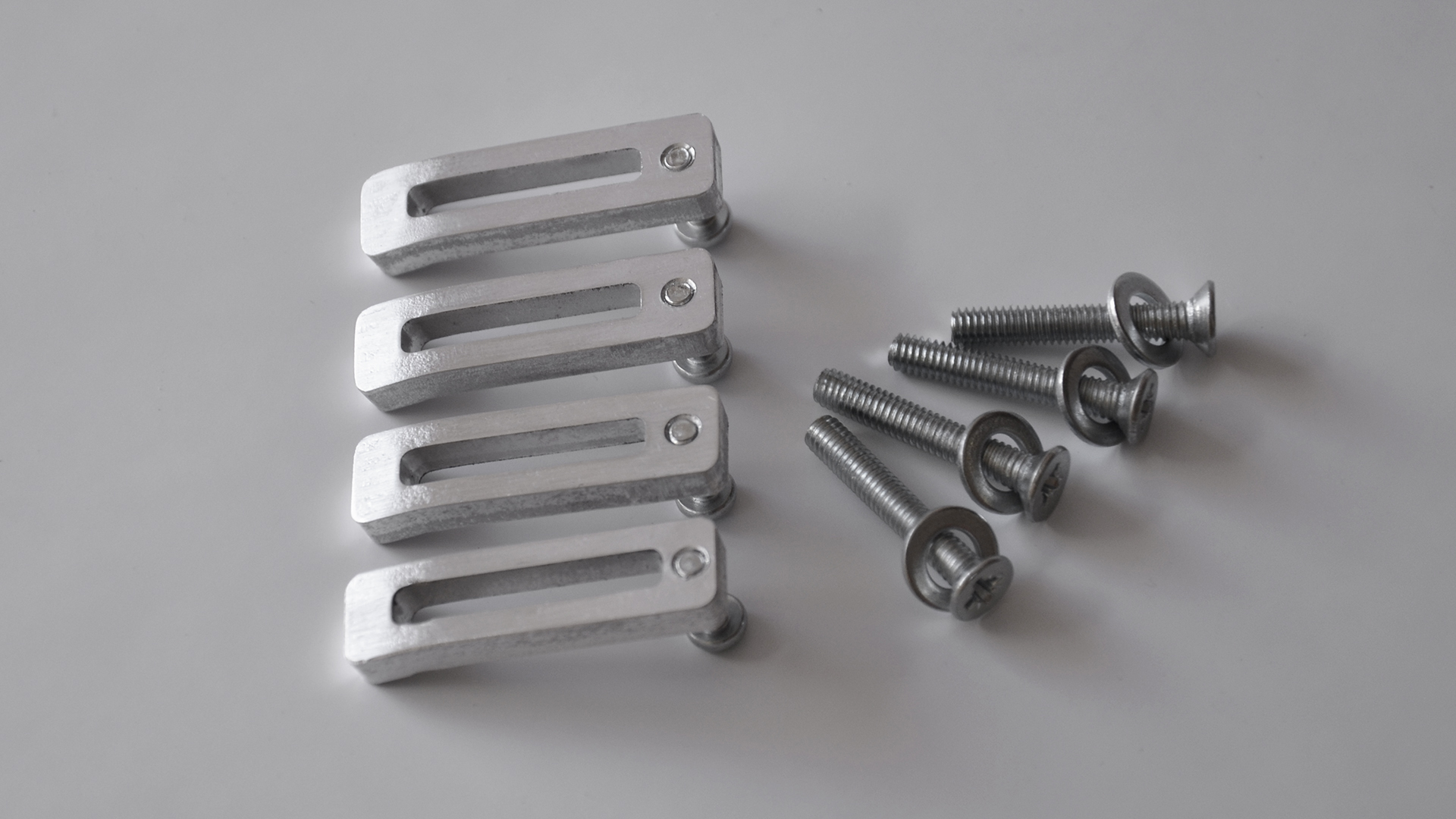
PCB Milling Bits are used for milling in this assignment.
|
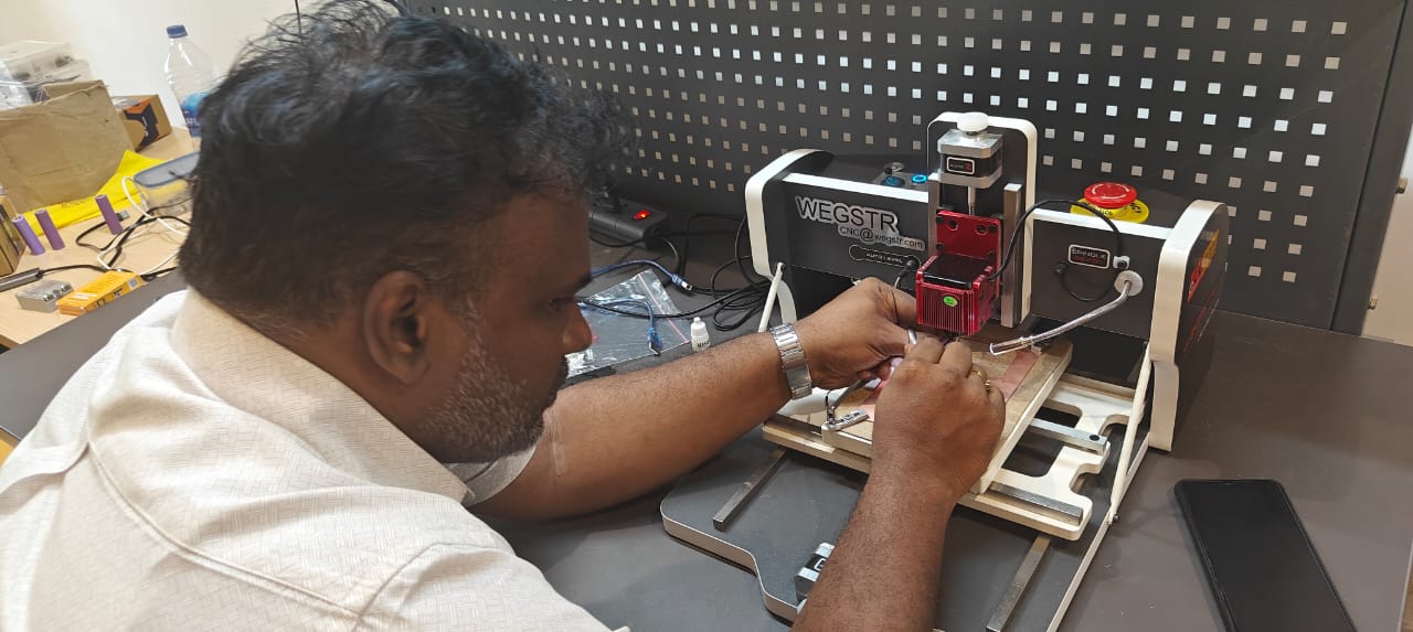
Set the machine to Zero, and after checking all parameters, we can start milling the PCB |
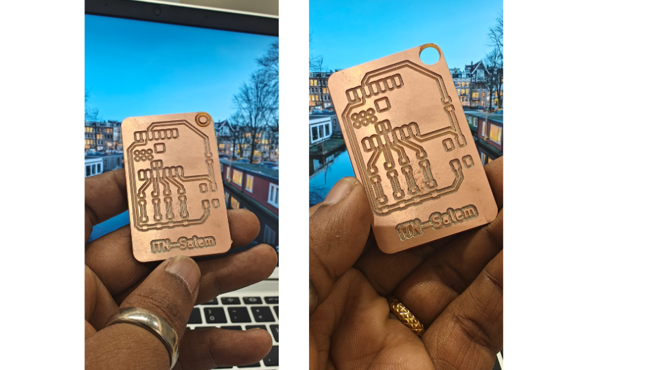
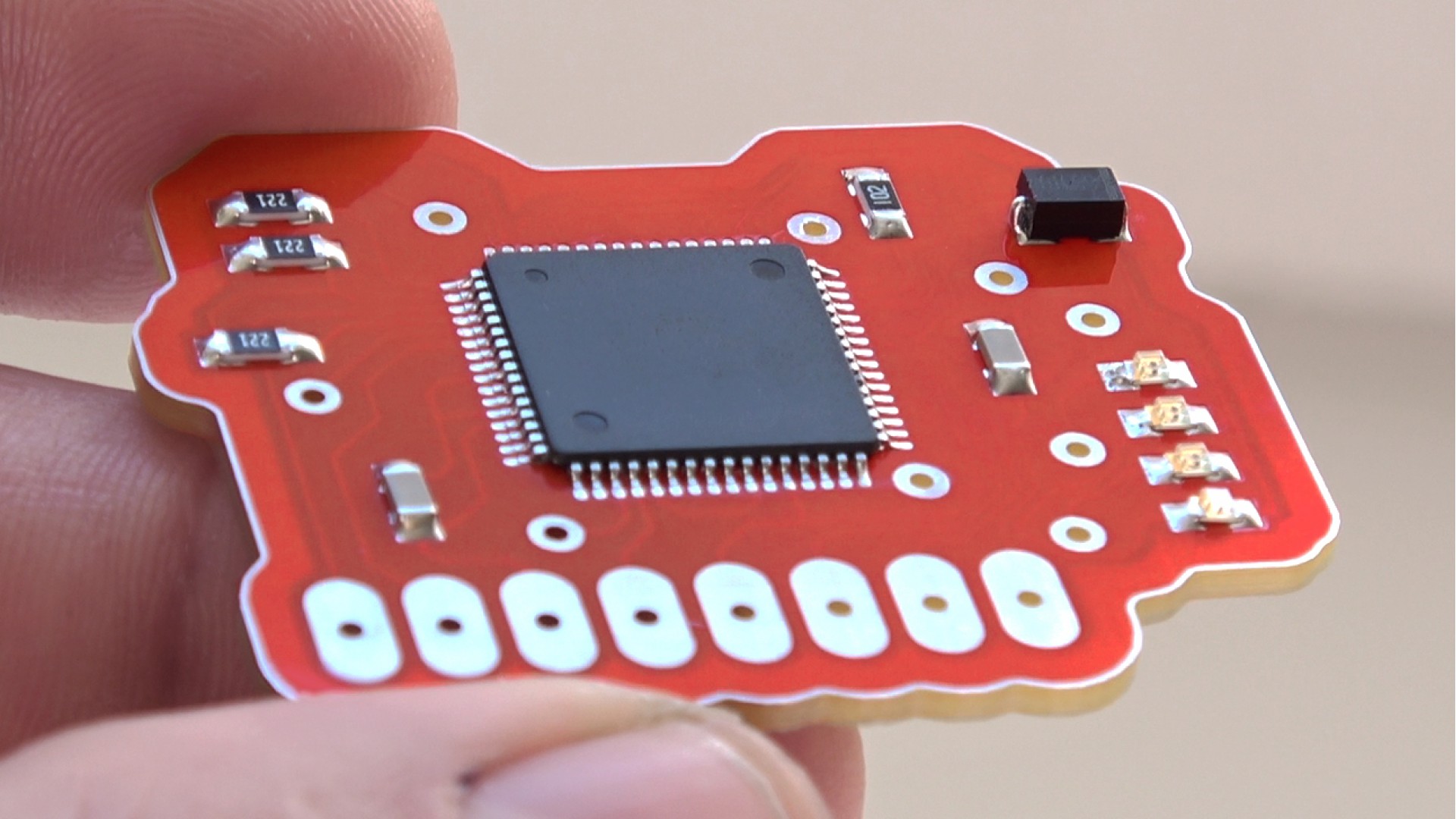
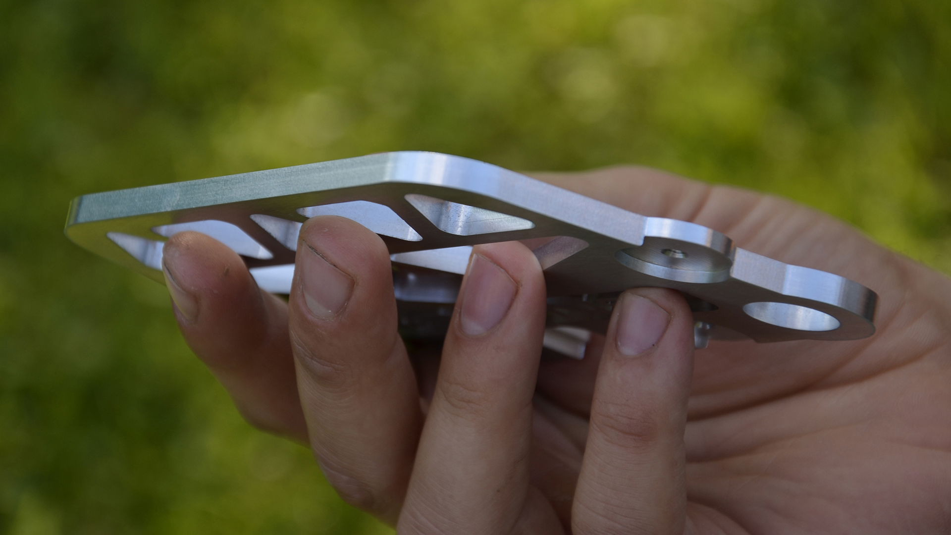
Final output of the milled PCB., After cleaning the oil residue, we can start soldering |
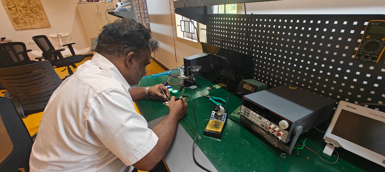
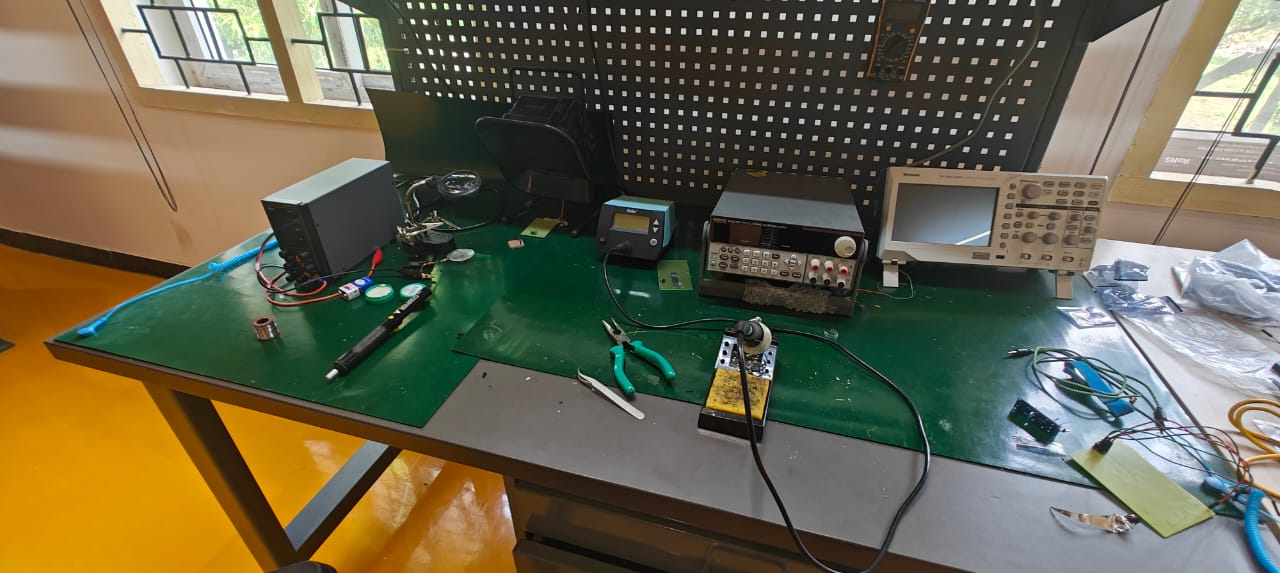
PCB workstation for soldering the PCB |
Components List
|
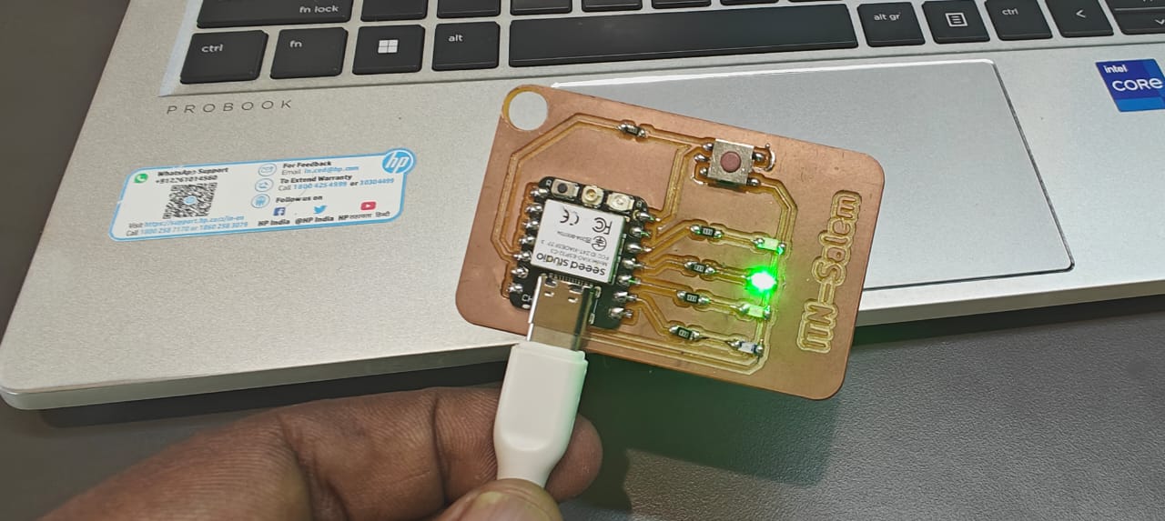
Push the code using Arduino IDE, and the design works seamlessly |
Demo video
Working video Link : LINK
KiCAD Files and PCB milling files : LINK
Code for Blink : LINK