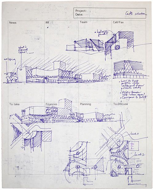
Hand Drawn
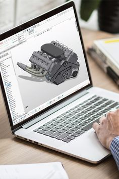
CAD Software
Week02
Assignment: Computer-Aided Design
Software used: Solidworks
What is Computer-Aided Design?
For generations, hand-drawn engineering drawings served as the language of engineering, facilitating communication among designers, manufacturers, and quality inspectors. With the advent of computers and their increasing capabilities, design engineers began leveraging design software to create virtual 2D and 3D models. These models enable the design of individual parts, their assembly into mechanisms, and the generation of final engineering drawings essential for manufacturing.
Hand Drawn | CAD Software |
Images - pinterest.com
Computer-Aided Design Softwares
2D - AutoCAD by AutoDESK | 3D - FreeCAD - Opensource | 3D - Solidworks by Dassault Systems |
3D - Creo by PTC | 3D - CATIA by Dassault Systems | 3D - NX CAD by Siemens |
Short History of Solidworks
SolidWorks, a 3D CAD tool, was developed by MIT graduate Jon Hirschtick in 1993 with the goal of creating a user-friendly and cost-effective CAD program for Windows. The first product, SolidWorks 95, was released in 1995. In 1997, the French software company Dassault Systèmes acquired SolidWorks and now offers a range of CAD tools.(Source : Wikipedia)
Concept Design Problem Statement
Design of a compliant mechanism clothespin, minimizing part count, suitable for 3D printing, and optimized for mass production via plastic injection molding.
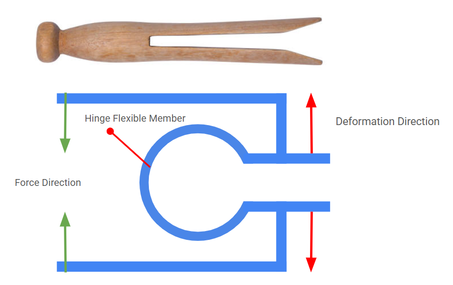
Compliant Mechanism
The compliant mechanism is a type of mechanism system that can achieve motion and force transmission through flexible members. Using CM concept a single-piece flexible system can replace multiple parts and assembly. A more simplified version of a mechanism can effectively reduce the system's weight, be easy to manufacture, and be cost-effective.
To Know more about Compliant Mechanism - NPTL Link
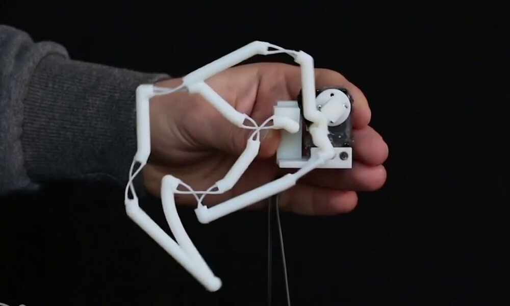
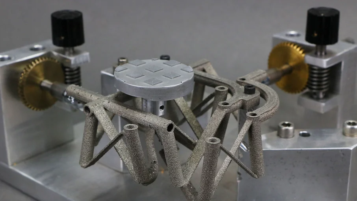
Simple Switch | Walking Mechanism | Satellite Application |
Source: Brigham Young University CMR
Conventional Clothespin:
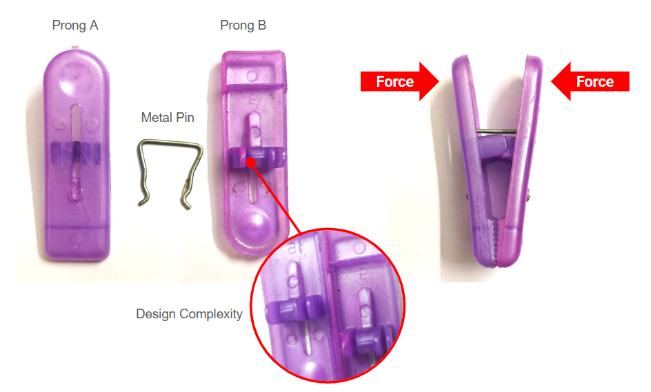
Traditional clothespin consist of multiple components, including two prongs and a metal spring. The complex design of the prongs, necessary for both connection and the central hinging action, complicates the injection mold tooling and necessitates an assembly line for final product construction.
My Design Concept:
Inspired by the 19th-century one-piece wooden peg patented by Jeremie Victor Opdebec. A wedge-shaped two prongs which can squeeze the cloths in between. Source: Wikipedia
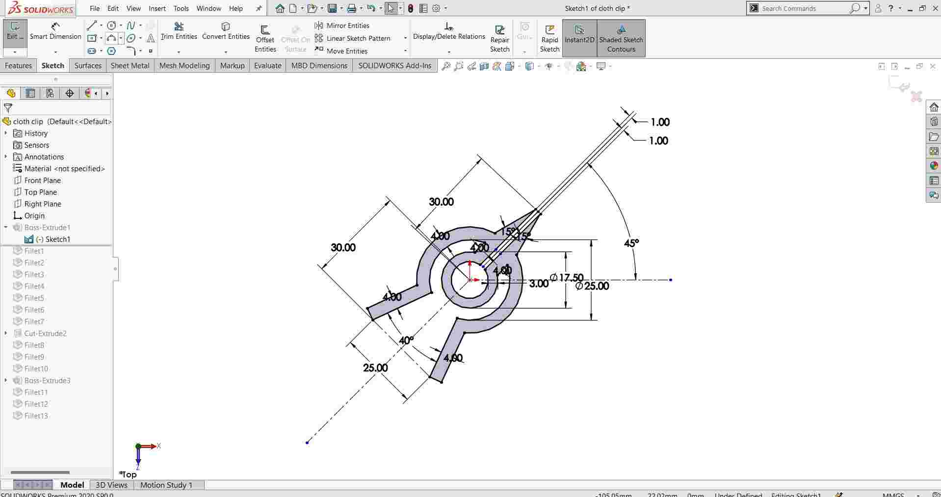
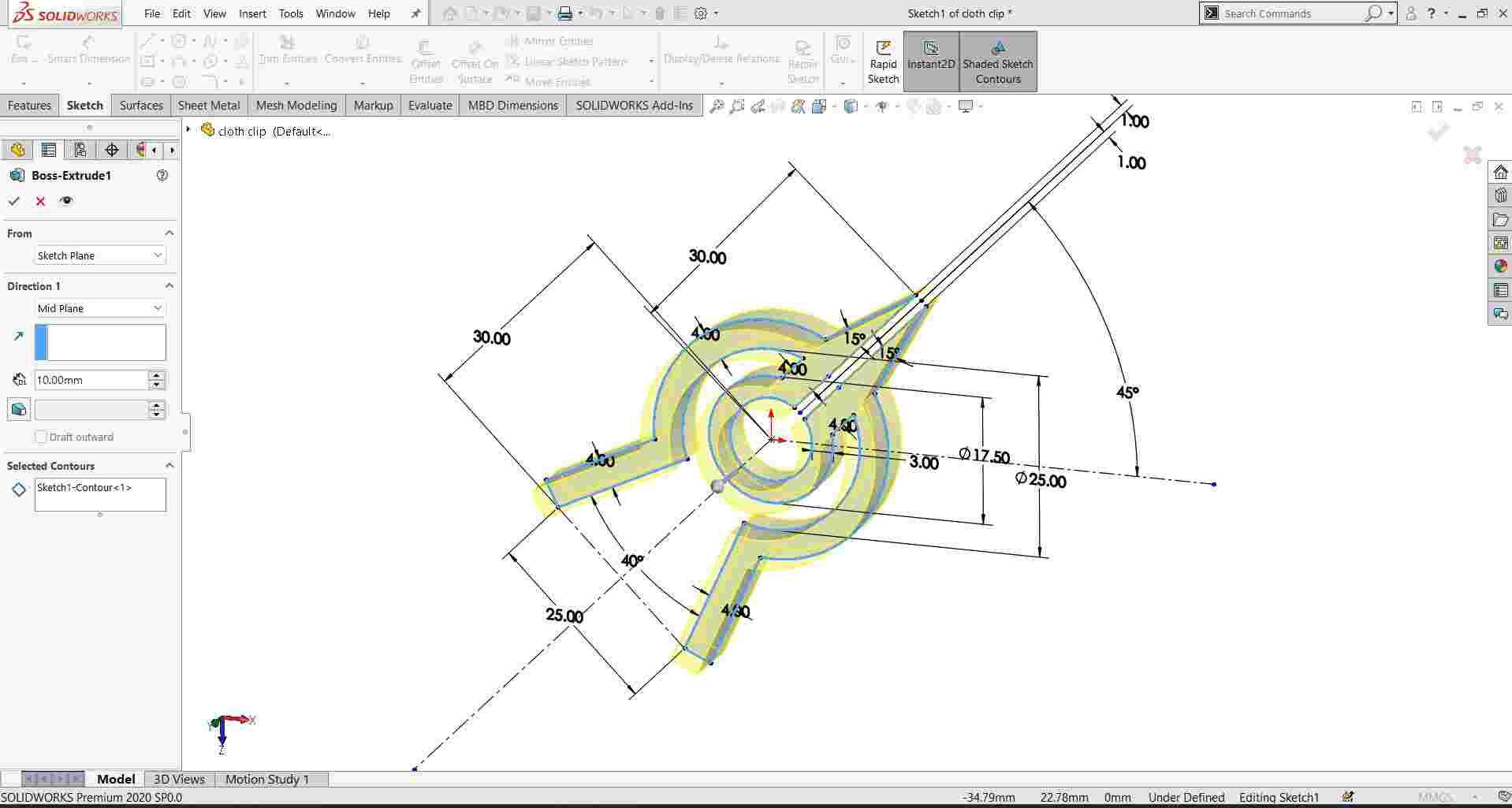
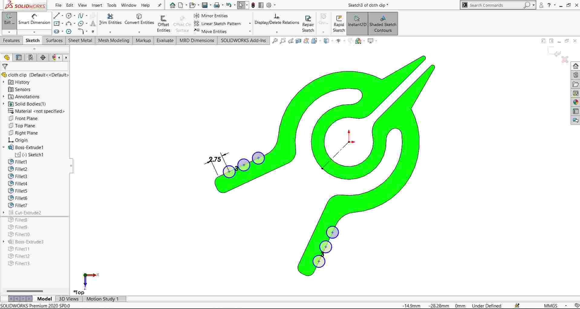
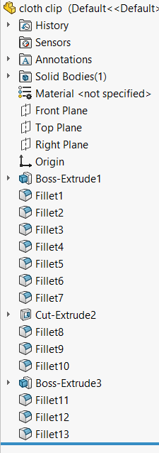
SolidWorks Design steps:
Features Used | Image |
Sketch | |
Extrude | |
Extrude Cut | |
Fillet | |
Steps in Design | |
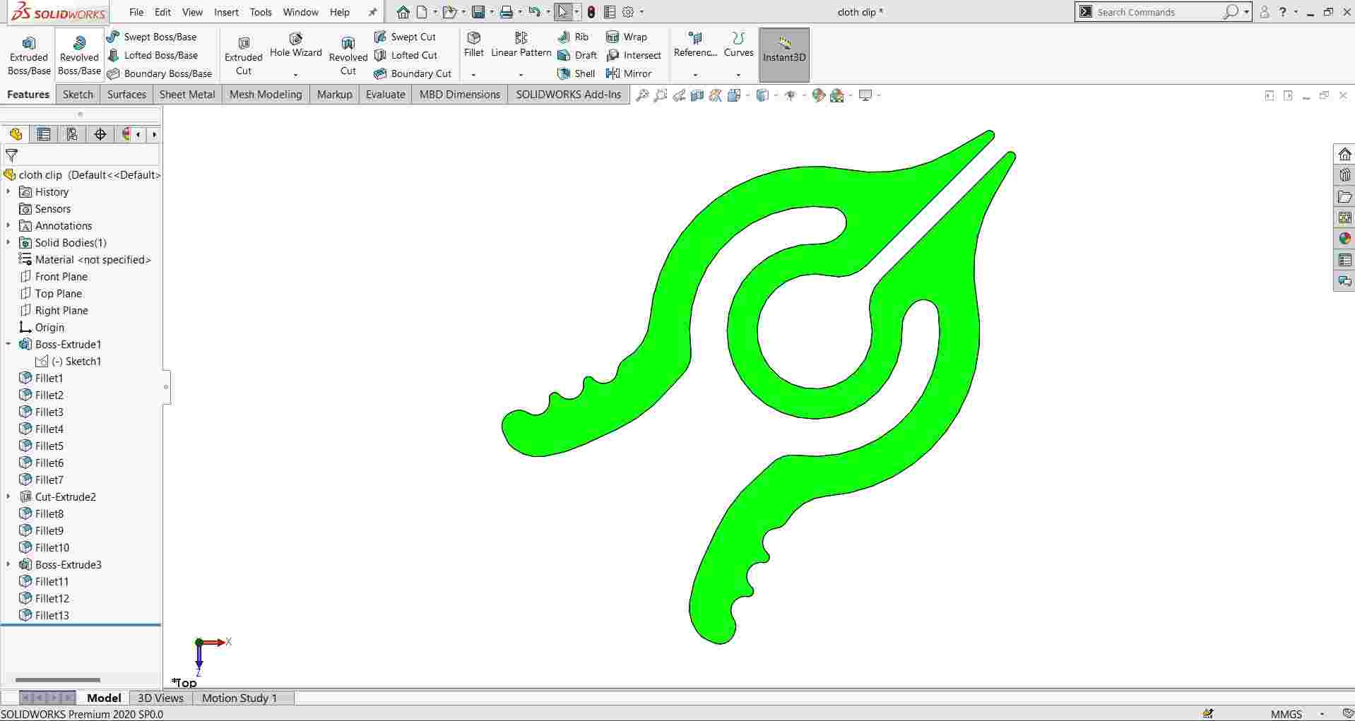
Finite Element Analysis Simulation | |
Model link
3D Printed using FDM machine and PLA material
3D Model Download Link: Link
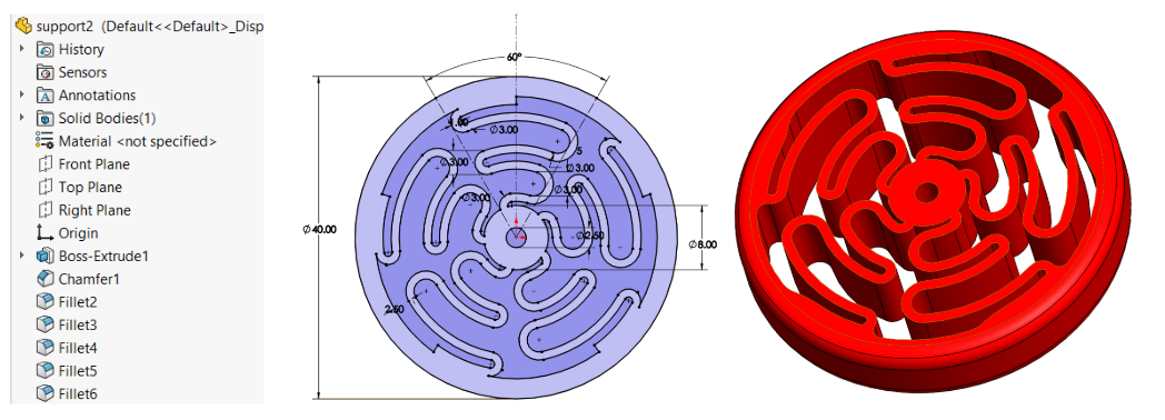
Example 2 for Compliant Mechanism
Wheel design for RC Car model with self-shock absorption
Model link
Assignment - 3D - Blender
For creating organic models using Blender
Blender! It's more than just a piece of software; it's a vibrant, open-source powerhouse in the world of 3D creation. Imagine a digital workshop brimming with tools for sculpting, modeling, animating, simulating physics, rendering photorealistic images, and even video editing and compositing – all within a single, freely available package.
Think of it as the Swiss Army Knife for artists, designers, scientists, and hobbyists alike. Whether you're crafting stunning visual effects for a film, designing a new product, creating intricate game assets, or simply exploring the fascinating world of 3D, Blender offers a comprehensive and incredibly versatile platform to bring your ideas to life. Its active and supportive community further enriches the experience, providing a wealth of tutorials, resources, and collaborative spirit. It's a journey of continuous learning and boundless creative potential.
With Blender, I tried to create an organic model
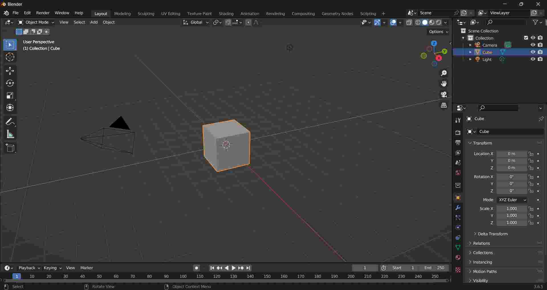
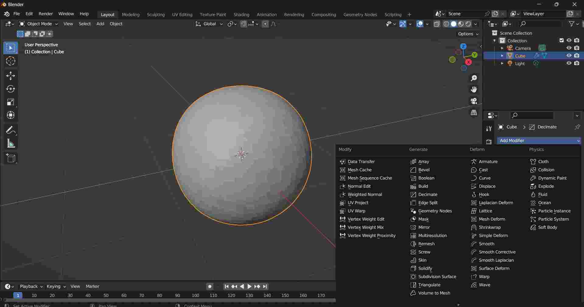
Open Blender, start a new file You will find a cube at the center of the screen |
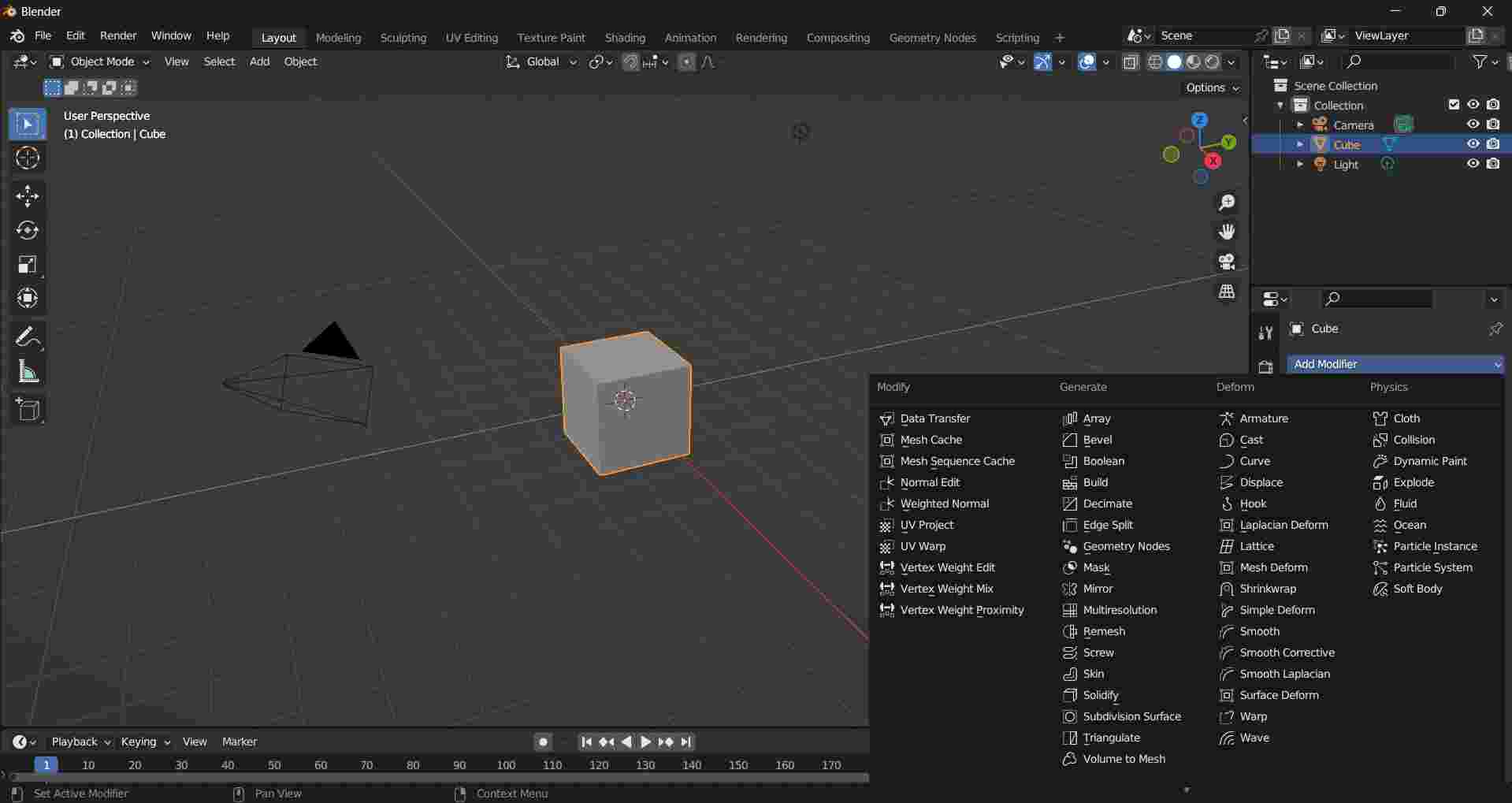
To convert the cube into a sphere use “Add Modifier” command Add - Subdivision Surface |
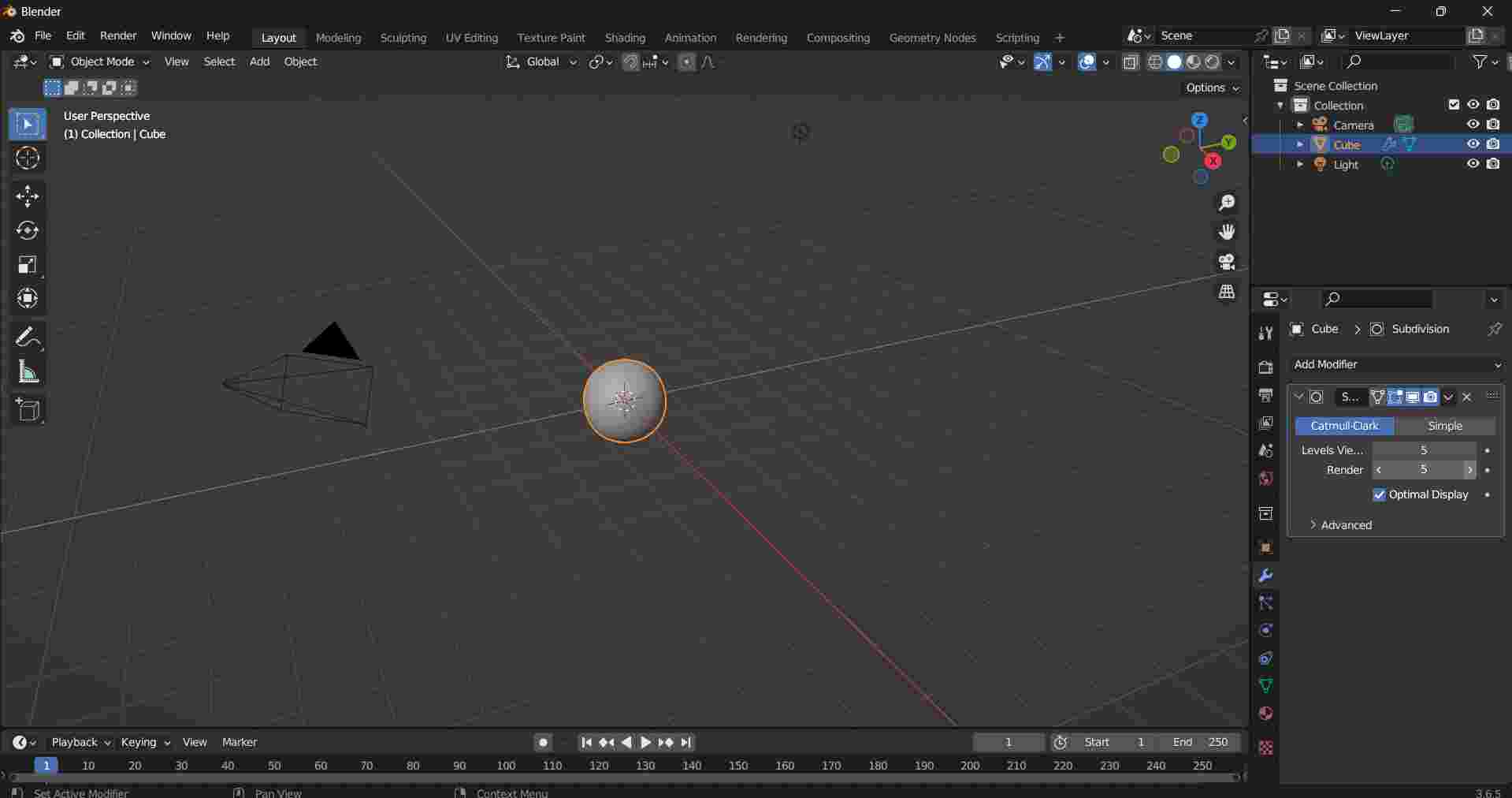
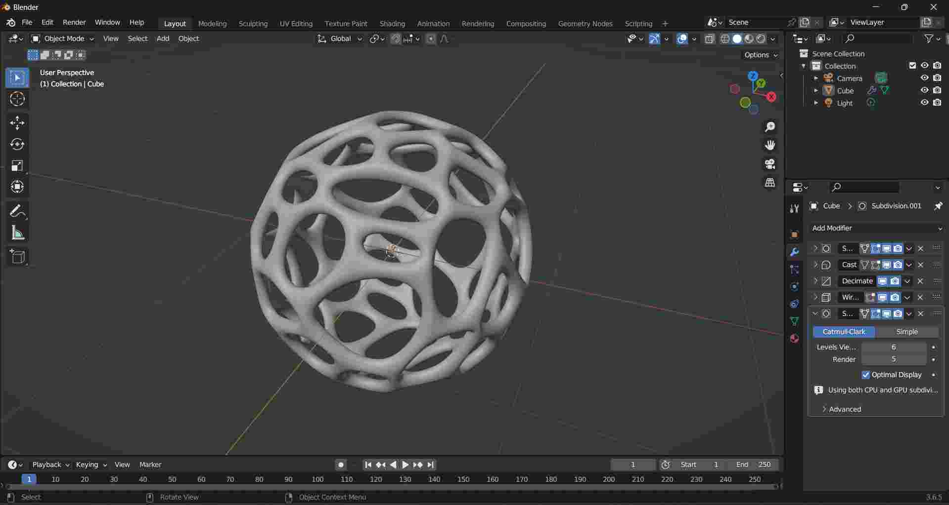
Add Values in Subdivision Surface Levels Vector = 5 Render = 5 (experiment with the values) |
In “add modifier” select “cast” |
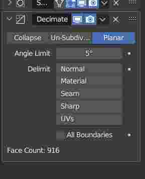
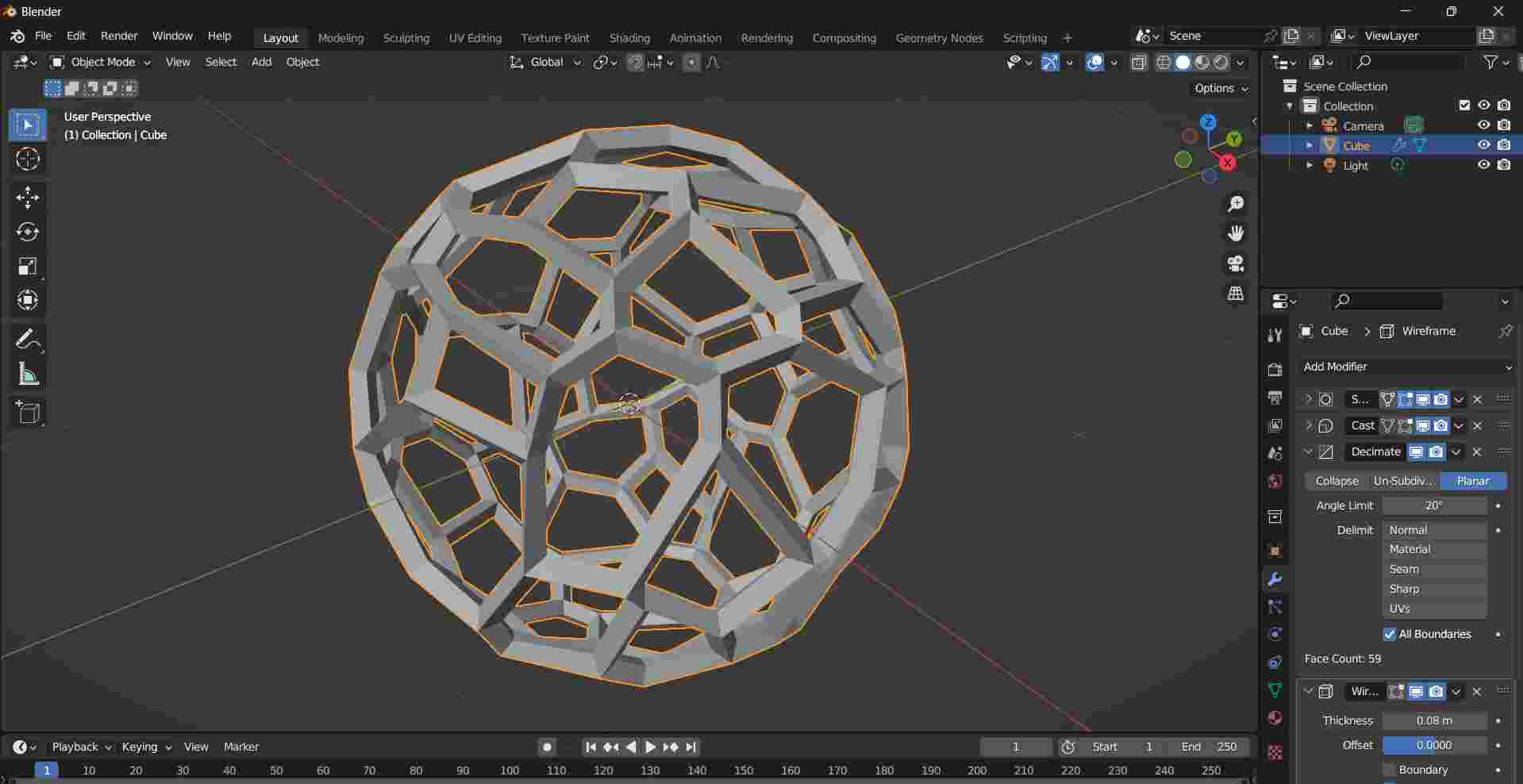
From “Add Modifier” select “Decimate” |
In decimate change, the angle limitis set to 20 degrees, you can experiment with the angle values to form different shapes. Dont forget to select “All Boundries” |
To smooth the edges select the “Subdivision surface” |
You can export the model to any format from the file->export option *.STL file for 3D printing. |
Blender Models Download Link : Link
Assignment - 2d - Vector imagesw02
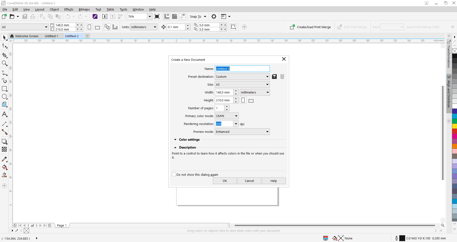
For creating vector images using CorelDraw
CorelDRAW is a vector graphics editor used for creating and editing images. It is developed and marketed by Corel Corporation. CorelDRAW is used for a wide variety of graphic design purposes, including logo design, illustration, page layout, and web design.
CorelDRAW was first released in 1989 and has since gone through many versions. The latest version, CorelDRAW 2021, was released in March 2021. CorelDRAW is available for Windows and macOS operating systems.
Assignment to create a vector image to print in a T-Shirt
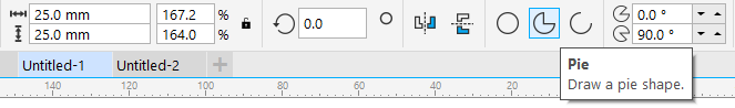
CorelDraw Screen |
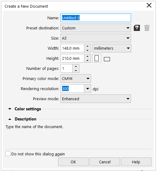
Page Setup |
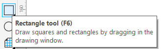
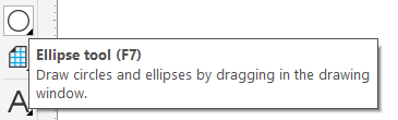
Tools used |
Steps in creating the vector image |
T-Shirt Print Order using VistaPrint website |
Image and Video Compression
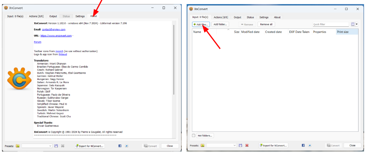
For image and video compression, I have used XnConvert
Download: XnConvert <<< Easy to download
About XnConvert |
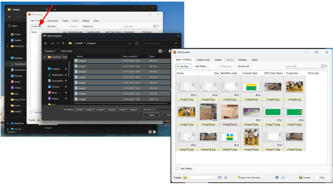
Select Files for Compression |
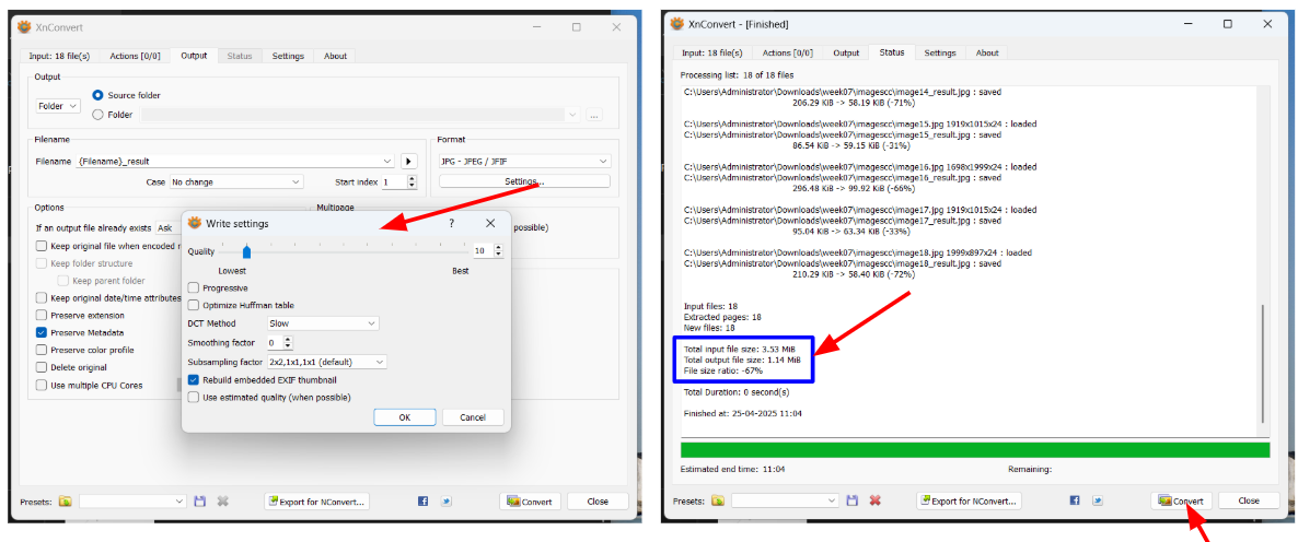
Settings |
Follow the simple steps as explained in the picture Input file size : 3.5MB -> Output file size : 1.14MB |