Electronics Design
Equipment | Description | Useful for | Tutorial (Rico’s recommendation) |
Regulated Power Supply | Provides a steady voltage to a device, regardless of changes in the input voltage | Testing electronic circuits and other devices (because they provide a stable voltage) | |
Multimeter | Measures electrical values like Voltage(AC, DC), Resistance, Capacitance, Continuity in one unit | To confirm that circuits and devices are safe and working properly. | |
Oscilloscope | Graphically displays varying voltages of one or several input signals as a function of time | Identifying the problem in a circuit, determining if a component has malfunctioned, identifying the shape of a wave, comparing several inputs graphically, etc. | |
Logic Analyzer | Captures and displays multiple digital signals from a circuit or system | For examining the behavior of digital signals over time, by analyzing the timing and logic states of various signals simultaneously. | |
Mixed signal | Can simultaneously analyze and test both analog and digital signals within a circuit | For testing integrated circuits (ICs) that contain both analog and digital components |
I then tested the final cast using a multimeter to check for conductivity or insulation, depending on the material’s purpose. This step ensured the resin behaved as expected—non-conductive in this case—confirming it is safe and suitable for use in electronic or decorative applications where electrical properties matter.
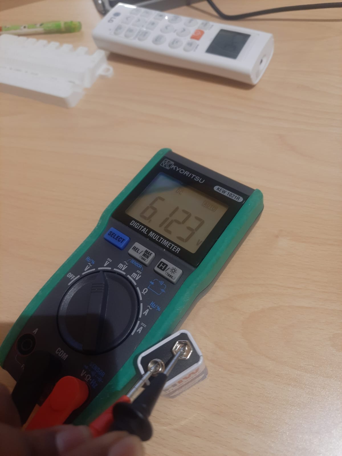
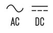
This test is useful for checking if the voltage at different points in the circuit is within the expected range; this can helps us confirm if a power source is providing the correct voltage, checking for potential problems in wiring/connections, if a switch is properly switching voltage, etc. The Multimeter can test for either AC Current and DC Current. You can distinguish them with these symbols;
Most of the time we will be measuring a DC, and under 20 V.
Steps:
1. Turn on the Multimeter.
2. Turn the knob on the Multimeter to select AC or DC, and maximum voltage of the power source you want to measure. This time, we tested DC voltage of <20V
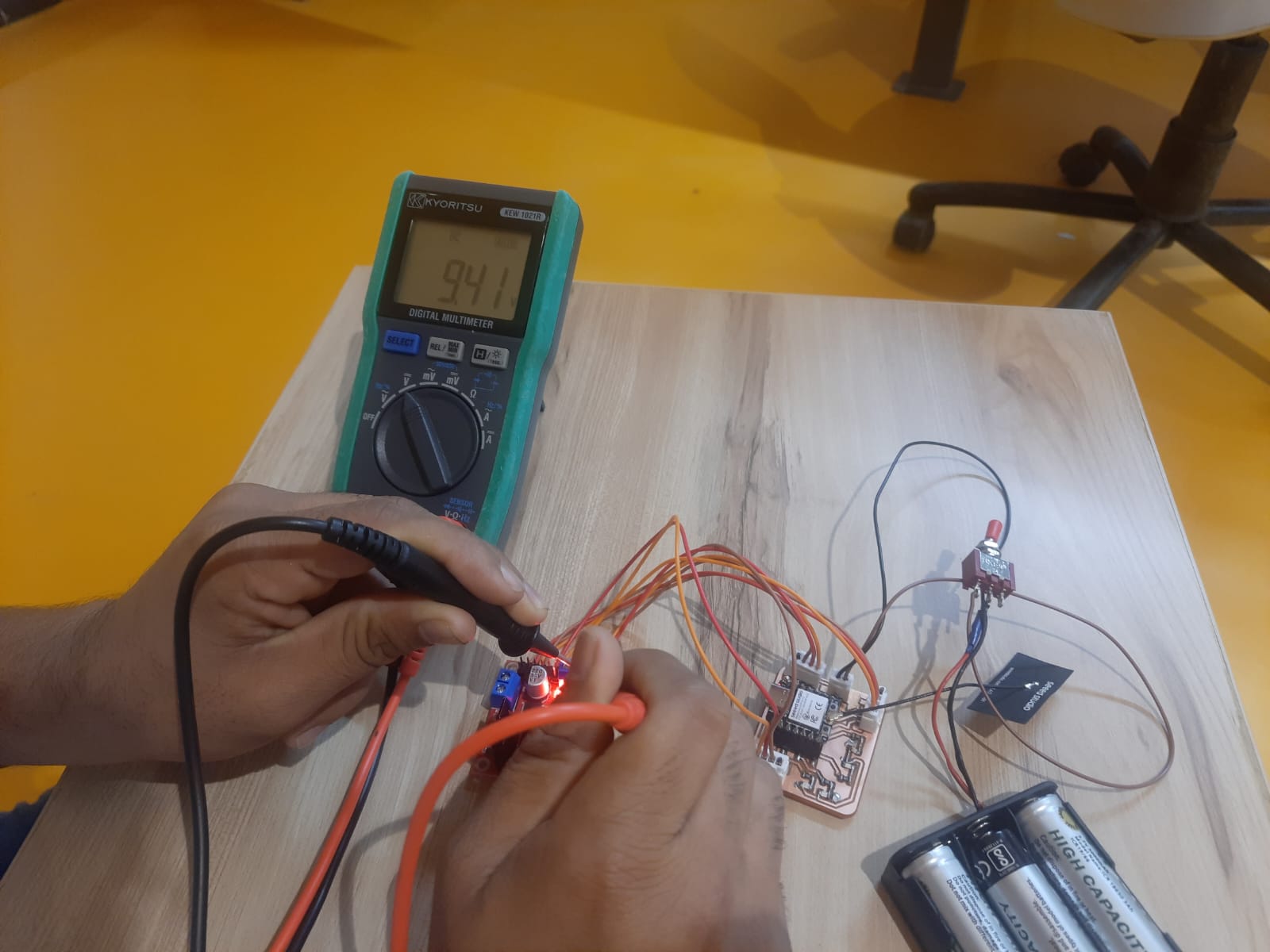
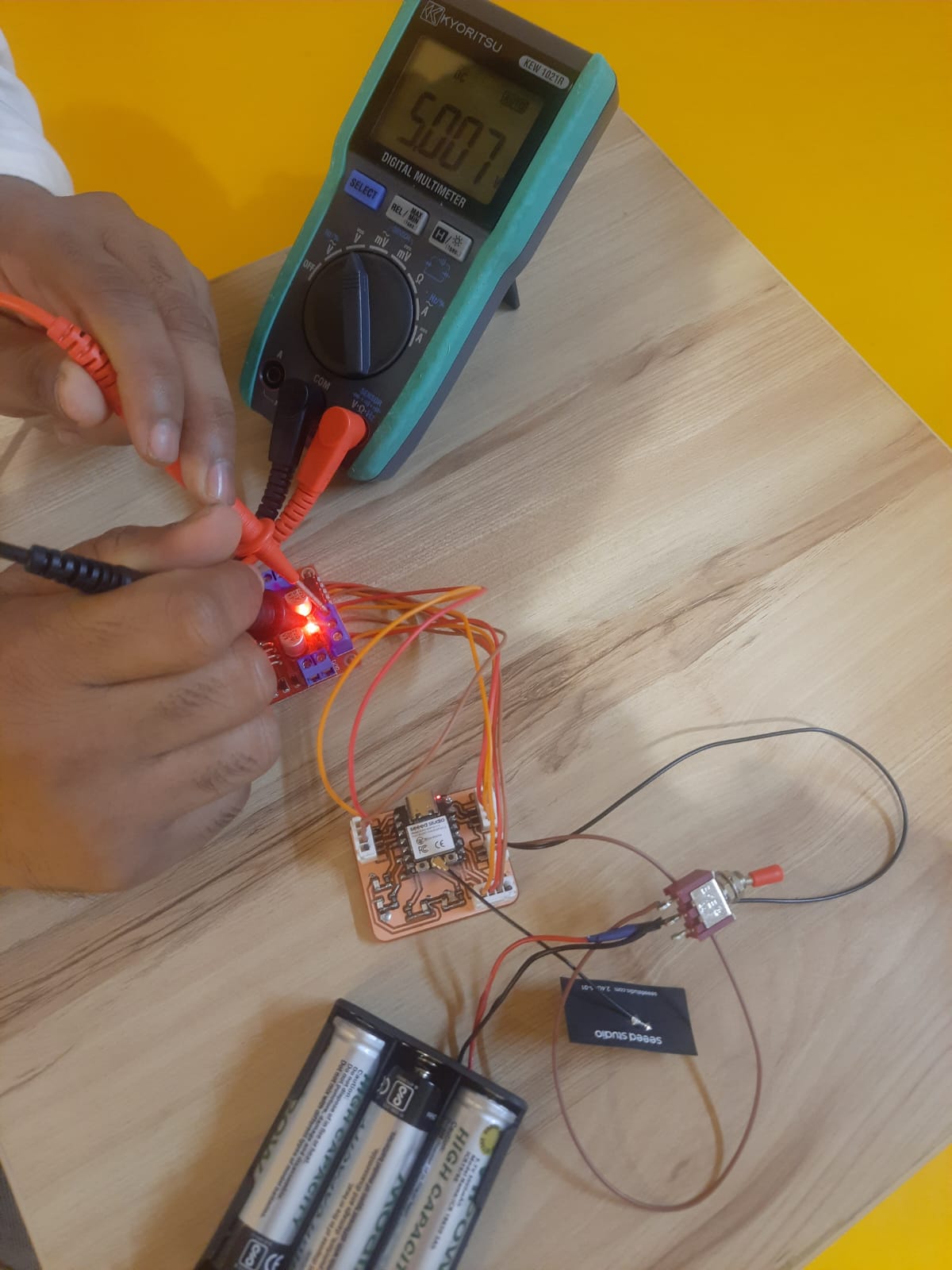
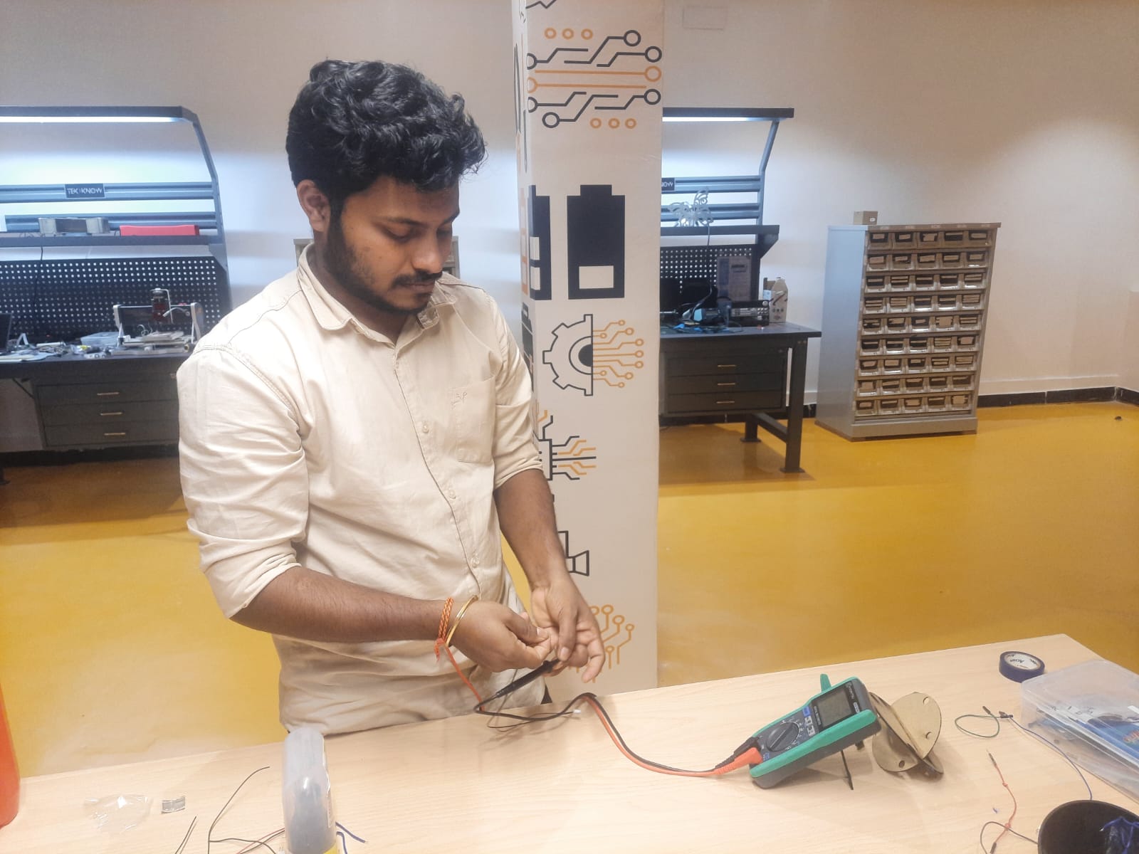
3. Touch the probes to Negative and Positive poles of the device
Remember!
First, touch the Black probe to Ground (negative) pole
Then touch the Red probe to Positive pole
I connected a 12V power supply to the motor driver module, which outputs both 12V for the motors and a regulated 5V for the controller or logic circuits. To ensure the outputs were correct, I checked both voltage lines using a multimeter, confirming stable 12V and 5V outputs as expected.
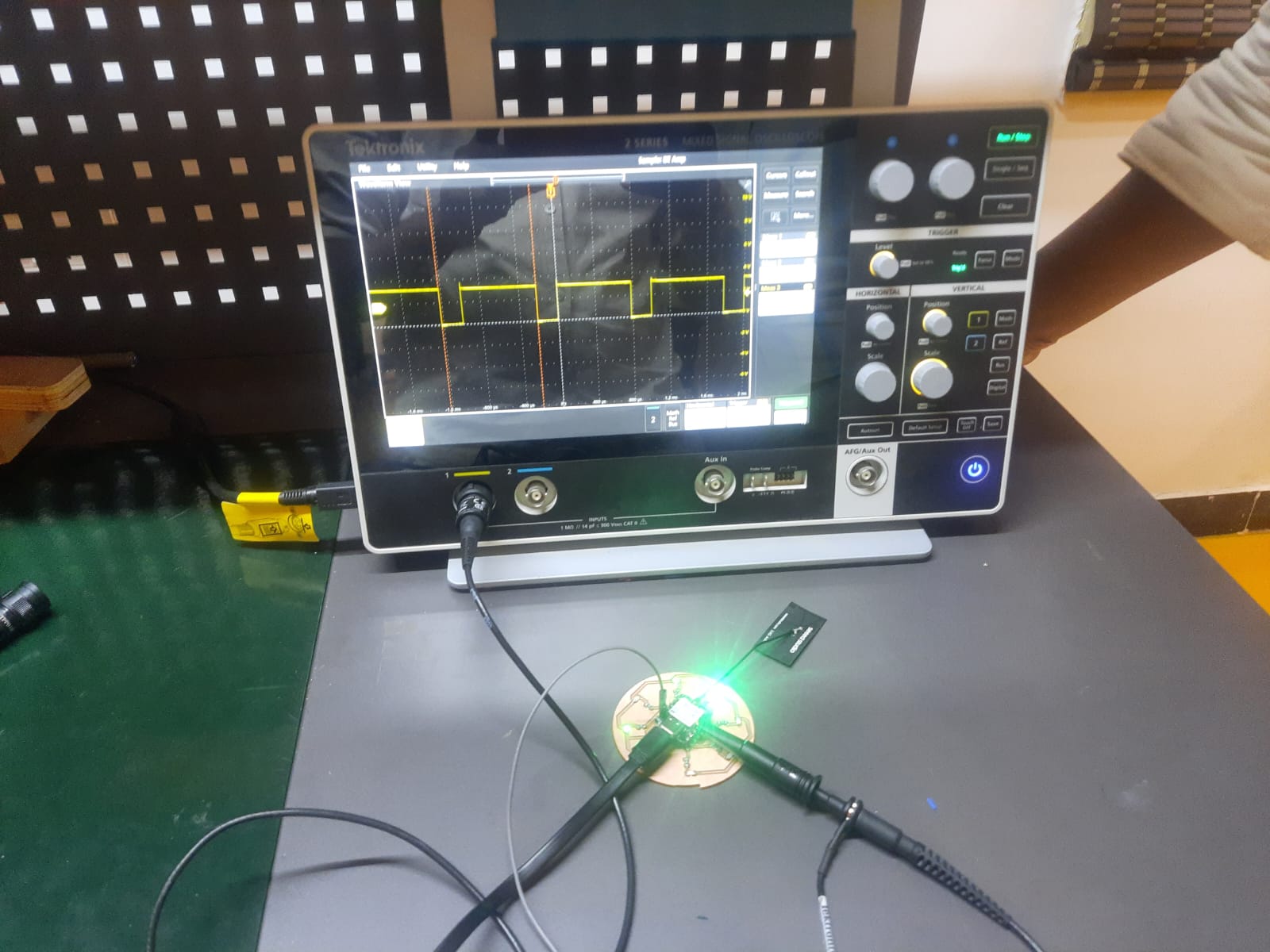
Oscilloscope allows us to observe parameters such as frequency, amplitude, and waveform shape, as a function of time. This help understand how voltage and current change across the circuit (the waveform) and verify if a device is correctly sending or receiving data. This helps with identifying issues like timing errors, signal integrity problems, noise, and other anomalies in a circuit, enabling us to pinpoint the source of malfunctions and make necessary adjustments to the design.
So small, it's kind of a big deal. Weighing in at less than four pounds and just 1.5 inches thick, this tiny, yet mighty scope can go seamlessly from bench to field and back again. Plus, with the battery option giving you hours of cordless power, you'll discover a whole new level of freedom on the job.
Turn on the machine and select settings such as AC.
We made a blinking LED circuit (blink every 100 milli seconds), and attached the positive probe to the circuit and negative probe to the Ground.
At first, the scale is usually too big, so we need to calibrate the machine by touching the probe, and adjusting the dials.
One calibrated, we could read the square-wave pattern of blinking LED.
We changed the blinking speed to LOW=500 milli seconds, HIGH=100 milli seconds to observe the change in waveform shape.