Group Assignment: Measure the Power Consumption of an Output Device
Individual Assignment: Add an Output Device to a Microcontroller Board You’ve Designed
1. Title Page
Project Title: RFID-RC522 with LCD on XIAO RP2040 (Fixed)
2. Introduction
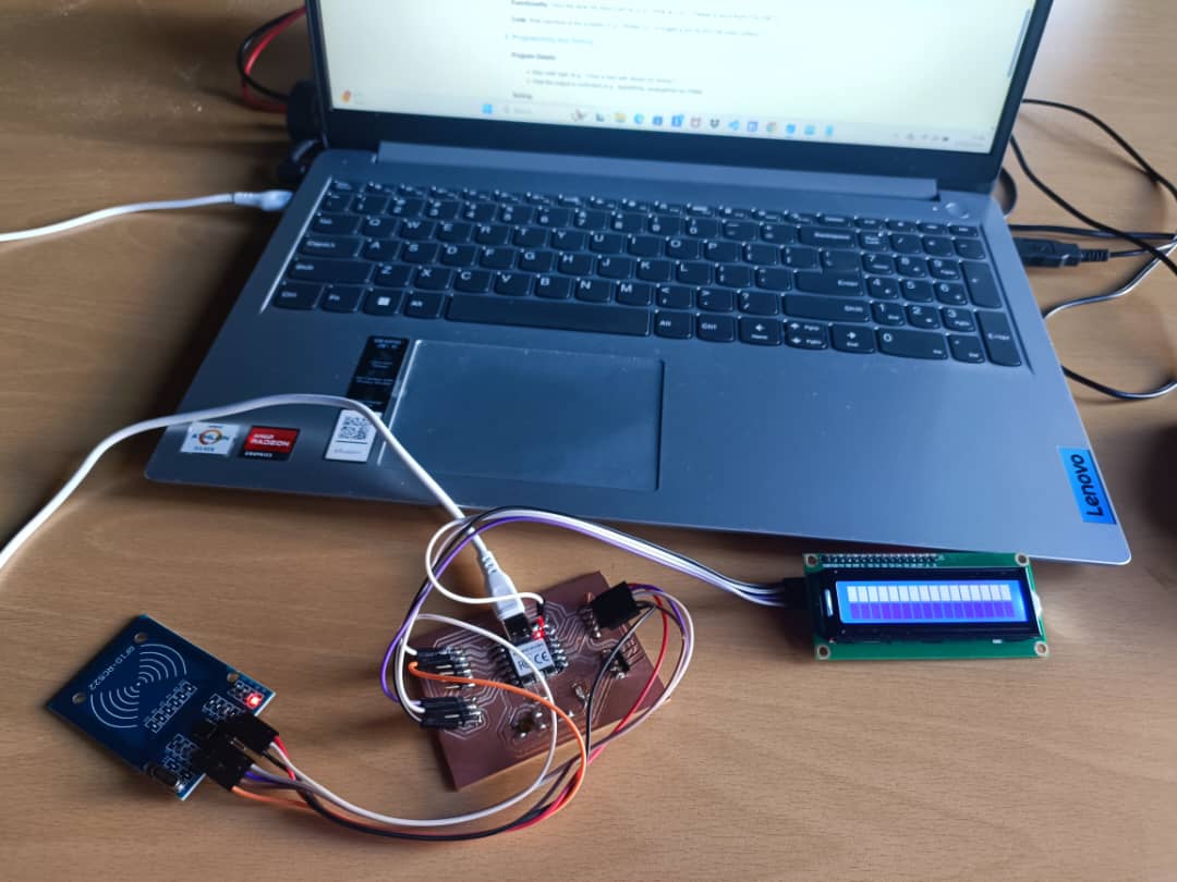
Objective: The PCB integrates a Seeed XIAO RP2040 module with an RFID-RC522 sensor and a 16x2 LCD display (I2C). The design uses the XIAO RP2040’s onboard power regulation and headers for connections.
3. Microcontroller Board Design
Components List:
- Microcontroller:Seeed XIAO RP2040 module
- Power:Supplied via USB-C to the XIAO RP2040, providing 3.3V to RFID-RC522 and 5V to LCD
- Headers: GPIO breakout (J2, J4, etc.) for SPI and I2C connections
- Programming Interface:USB-C on the XIAO RP2040 for bootloader and programming
Schematic Diagram: Hand-drawn or software-generated by KiCad.
Description: Explain the board design and how it supports the output device.
The board design integrates the Seeed XIAO RP2040 microcontroller module with a 16x2 LCD display (connected via I2C) and an RFID-RC522 reader. The layout ensures that each component is easily accessible through clearly labeled header pins, with dedicated traces for power (3.3V or 5V as required), ground, and data lines.
The XIAO RP2040 module includes onboard voltage regulation, which powers both the microcontroller and peripheral devices. The LCD display, as the primary output device, is supported via the I2C bus using the SDA and SCL lines, minimizing the number of pins needed and reducing wiring complexity. Pull-up resistors on the I2C lines ensure stable communication.
Capacitors are placed near the power supply lines to smooth out voltage fluctuations, ensuring stable operation for both the microcontroller and the display. Mounting holes and headers allow the LCD to be secured and connected without strain on the pins. Overall, the board design focuses on compactness, modularity, and reliable communication between components, especially to support real-time display of scanned RFID tag data.
4. Output Device Integration
Device Choice: 16 x 2 LDC (I2C) .
- Device Choice: A 16x2 LCD was chosen for its simplicity and clear visual feedback. It is well-suited for displaying RFID scan results.
- Connection: The LCD is connected via I2C using pins D4 (GP28) for SDA and D5 (GP29) for SCL. Power is supplied from the RP2040’s 5V and GND pins.
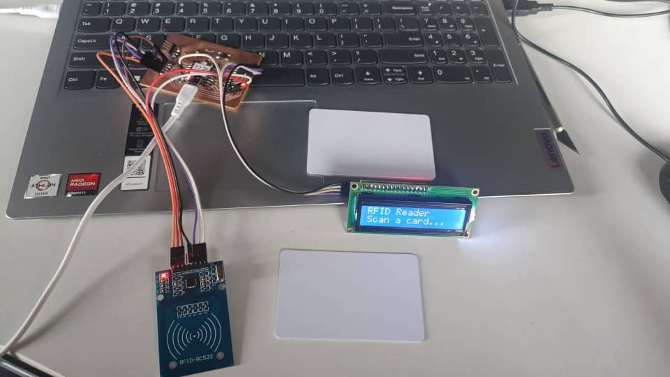
- Functionality: When an RFID card is scanned, the system checks the UID and updates the LCD to display the result, such as "New Card", "Card Recognized", or "Access Denied".
- Code: The firmware is written in C++ using the Arduino IDE. It uses lcd.init() for initialization and prints messages based on the RFID scan status. The code also ensures compatibility with the LiquidCrystal_I2C library, avoiding deprecated or unsupported functions like begin().
Connection: How the output device is wired to the SEED XIAO RP2040.
- Seeed XIAO RP2040 to MFRC522 (RFID Reader)
- SPI Communication
- Used to scan RFID cards/tags for identity or access control.
- Seeed XIAO RP2040 to 16x2 LCD (I2C)
- I2C Connection (SDA, SCL)
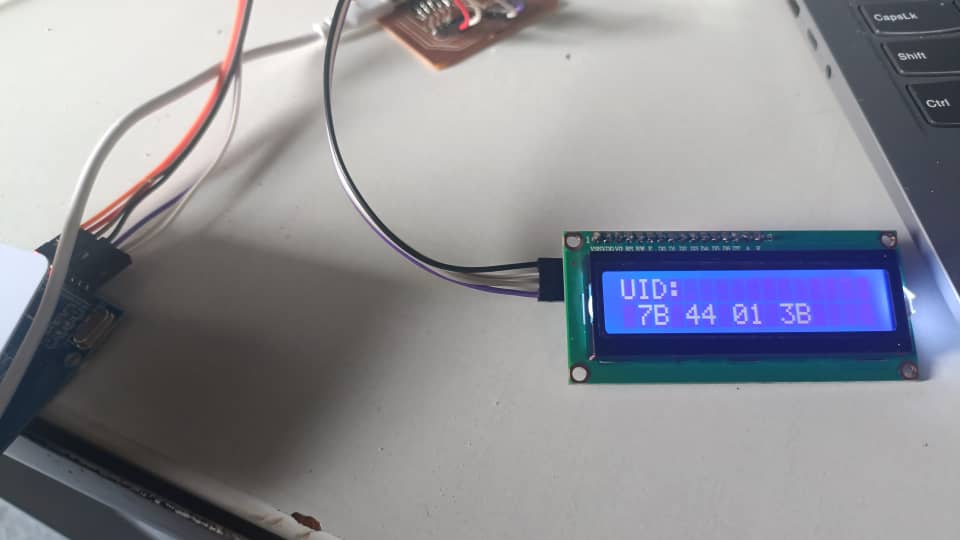
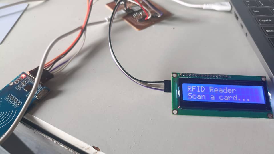
- Displays the status of scanned RFID cards, such as "UID tag: 7B 44 01 3B" or "RFID Reader scan a card...".
Operation Flow
- RFID tag is scanned using the MFRC522 module.
- Functionality: When an RFID card is scanned, the system checks the UID and updates the LCD to display the result.
- The scanned UID is checked against stored values in the RP2040.
- Status is displayed on the 16x2 LCD
Code Snippet:
                    #include <SPI.h>
                        #include <MFRC522.h>
                        #include <Wire.h;>
                        #include <LiquidCrystal_I2C.h>

                        #define RST_PIN     D0     // Reset pin
                        #define SS_PIN      D1    // Slave select pin

                        MFRC522 mfrc522(SS_PIN, RST_PIN);  // Create MFRC522 instance
                        LiquidCrystal_I2C lcd(0x27, 16, 2); // LCD address (0x27 or 0x3F), columns, rows

                        void setup() {
                          Serial.begin(9600);
                          SPI.begin();          // Init SPI bus
                          mfrc522.PCD_Init();   // Init MFRC522

                          // Initialize LCD
                          lcd.init();
                          lcd.backlight();

                          lcd.setCursor(0, 0);
                          lcd.print("RFID Reader");
                          lcd.setCursor(0, 1);
                          lcd.print("Scan a card...");

                          Serial.println("RFID Reader Ready");
                          Serial.println("Scan a card...");
                        }

                        void loop() {
                          // Look for new cards
                          if (!mfrc522.PICC_IsNewCardPresent()) {
                            return;
                          }

                          // Select one of the cards
                          if (!mfrc522.PICC_ReadCardSerial()) {
                            return;
                          }

                          // Show UID on serial monitor
                          Serial.print("UID tag: ");
                          String content = "";

                          for (byte i = 0; i < mfrc522.uid.size; i++) {
                            Serial.print(mfrc522.uid.uidByte[i] < 0x10 ? " 0" : " ");
                            Serial.print(mfrc522.uid.uidByte[i], HEX);
                            content.concat(String(mfrc522.uid.uidByte[i] < 0x10 ? " 0" : " "));
                            content.concat(String(mfrc522.uid.uidByte[i], HEX));
                          }

                          Serial.println();
                          Serial.print("Message: ");
                          content.toUpperCase();

                          // Display UID on LCD
                          lcd.clear();
                          lcd.setCursor(0, 0);
                          lcd.print("UID:");

                          lcd.setCursor(0, 1);
                          for (byte i = 0; i < mfrc522.uid.size; i++) {
                            lcd.print(mfrc522.uid.uidByte[i] < 0x10 ? " 0" : " ");
                            lcd.print(mfrc522.uid.uidByte[i], HEX);
                          }

                          delay(2000); // Wait 2 seconds before next scan
                          lcd.clear();
                          lcd.setCursor(0, 0);
                          lcd.print("RFID Reader");
                          lcd.setCursor(0, 1);
                          lcd.print("Scan a card...");
                        }
                        }
5. Programming and Testing
Program Details:
- Key code logic:
- The
loop()
function continuously polls for RFID cards using conditional checks, exiting early if no card is present. for
loops process the UID bytes for both Serial and LCD output.- delay(2000) provides a 2-second pause to display the UID before resetting the LCD, making timing
How the output is controlled
- Serial Monitor: Controlled via
Serial.print()
and Serial.println() at 9600 baud, outputting text (e.g., "UID tag: AA 6E 52 43"). - LCD: Controlled via LiquidCrystal_I2C functions
(lcd.print(), lcd.setCursor(), lcd.clear(), lcd.backlight()) over I2C,
displaying messages like "RFID Reader" and the UID. - No digitalWrite or analogWrite: The code relies on SPI (for RFID) and I2C (for LCD) protocols, with no direct GPIO or PWM control.
- Timing: Managed by
delay(2000)
to control how long the UID is shown on the LCD.
Testing:
- Scanned 2 cards repeatedly for 30 seconds
- Observations (e.g., "LED blinked consistently; slight flicker at low PWM values").
Results: Confirm the device performs as intended.
6. Deliverable
Submission Content:
- Schematic or photo of the microcontroller board
- Code snippet (e.g., main loop controlling the output)
- Brief description of the setup and what the device does
Optional: Plan for video/demo
7. Conclusion
Summary: Recap the design and functionality achieved.
The design performed as it was supposed to be. The use of the MFRC522, XIAO-RP2040 and the 16x2 LiquidCrystal_I2C is going to be used as the basis of an inventory Management system for the unicersity to reduce time and ensure that tools are always protected and tracked to avoid loss.
Challenges: It was really difficult to achive this functionality. The code would refuse to run the RFID-RC522, then after acheving it the LCD completely could not be deted. After two days I realised that it was because of a pin that was not well sodered in the development board.