System Integration
After building and testing each module of my DI-FARM project separately—including the PCB hardware, sensor network, wireless communication, and data dashboard, I brought all the parts together into one unified system. This final integration stage was about making sure all pieces talk to each other and function as a complete working solution.
Flow diagram that show how my system is integrated
_compressed.jpg)
Connecting Hardware and Firmware
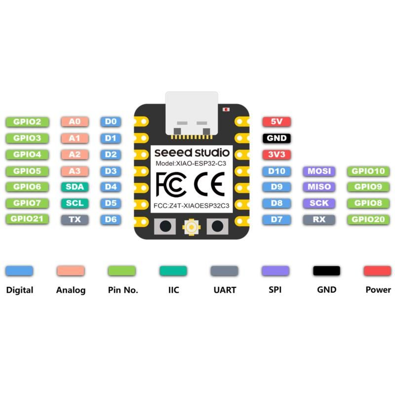
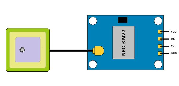
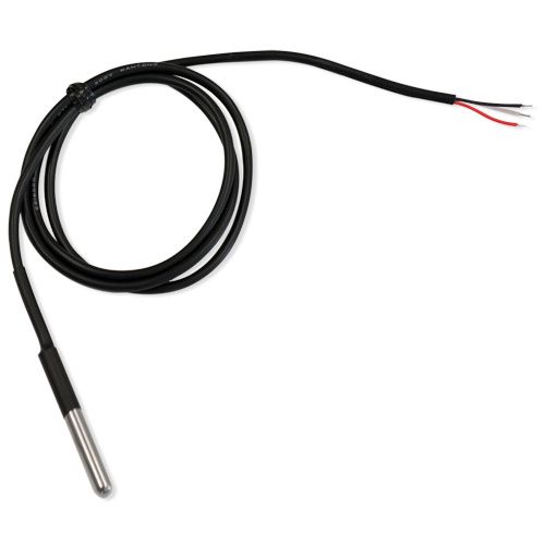
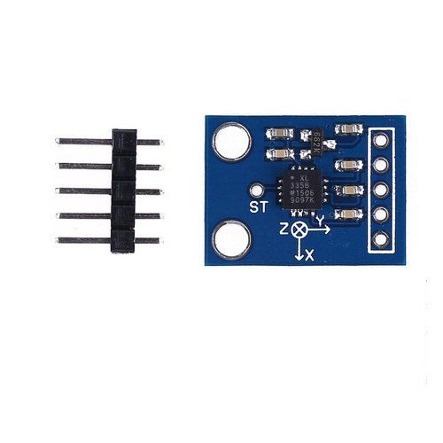
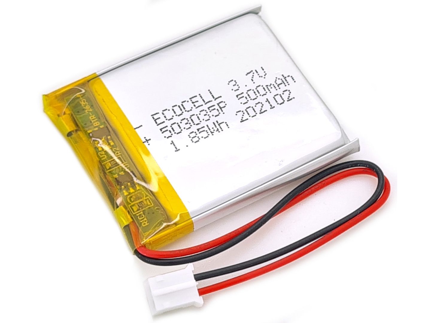
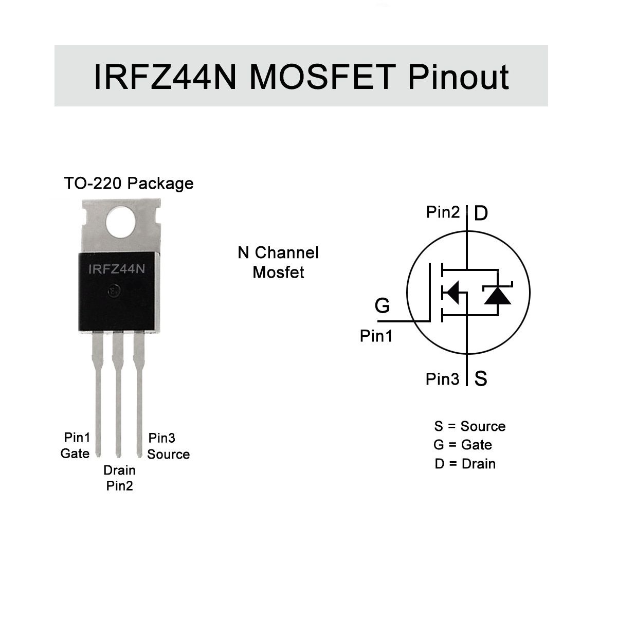
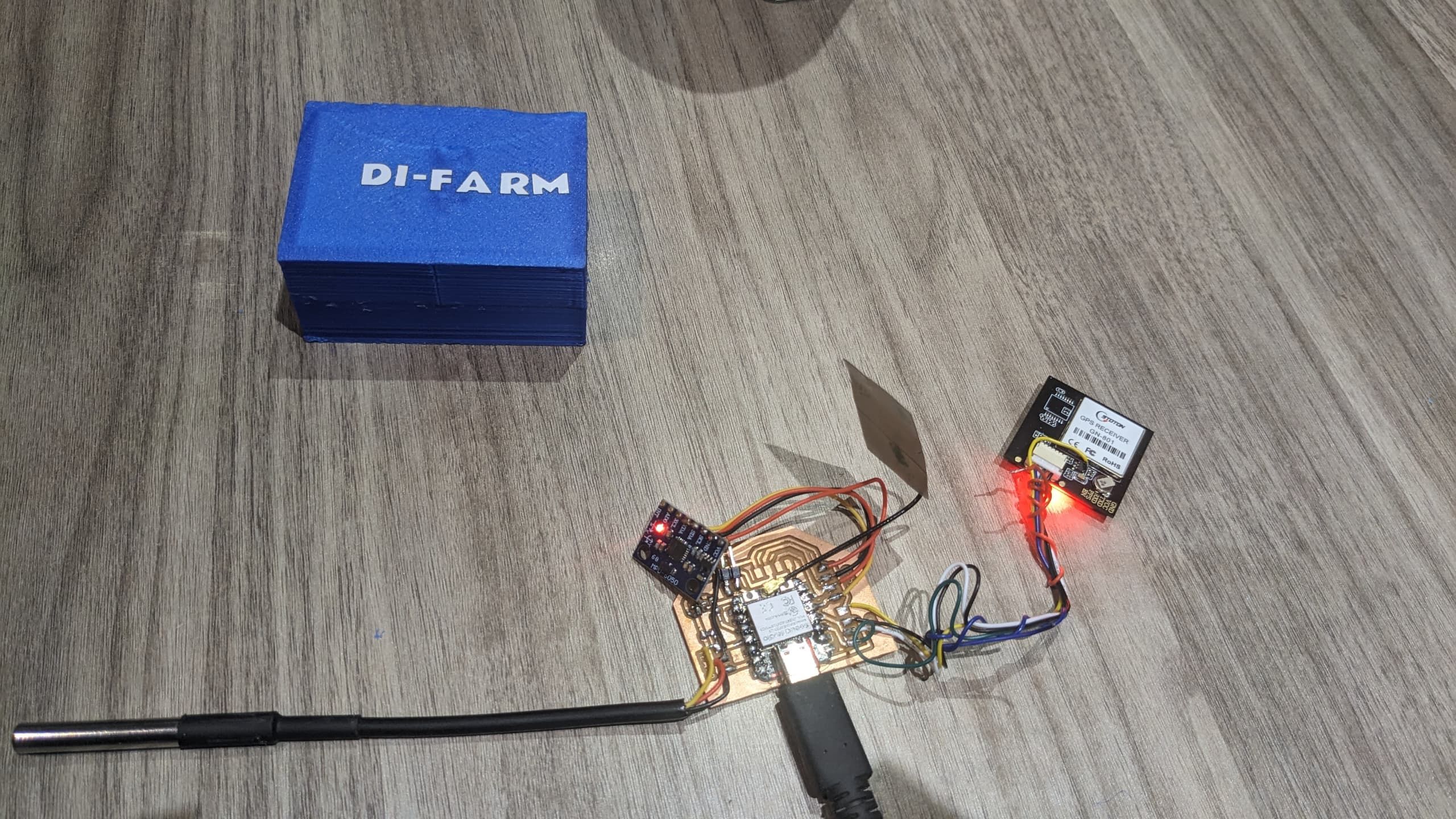
I started by assembling all hardware components: the PCB board with sensors (temperature, GPS, and accelerometer), ESP32 microcontroller, and power sources(LIPO Battery or wired). I then uploaded the final firmware which collects and sends data from sensors in real-time.
COMPONENTS I USED
Testing Live Data Flow
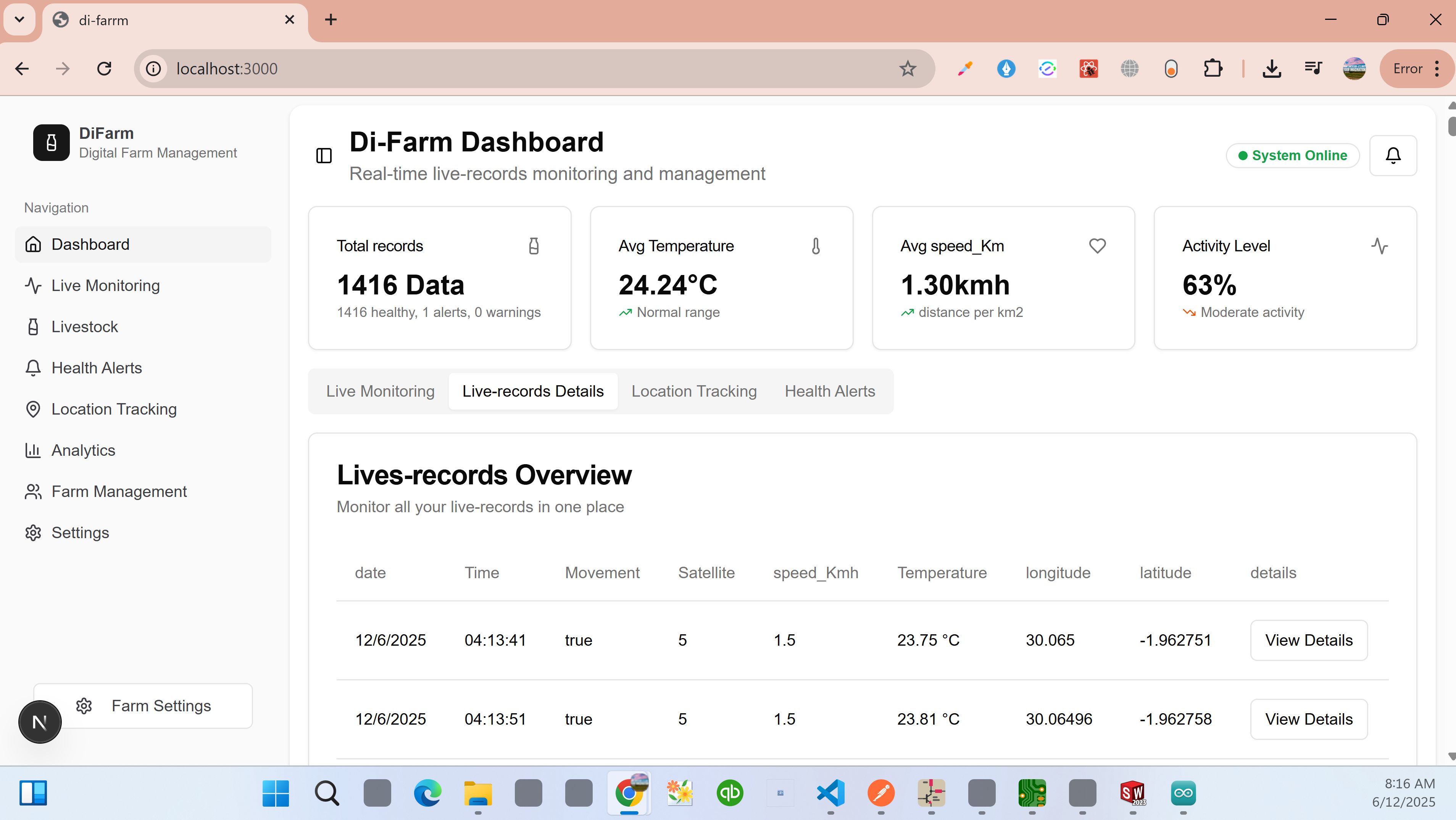
Once the device was running, I opened the backend server and dashboard. I walked with the device outdoors to collect GPS coordinates and temperature values. Within seconds, new data appeared on the dashboard, confirming successful integration.
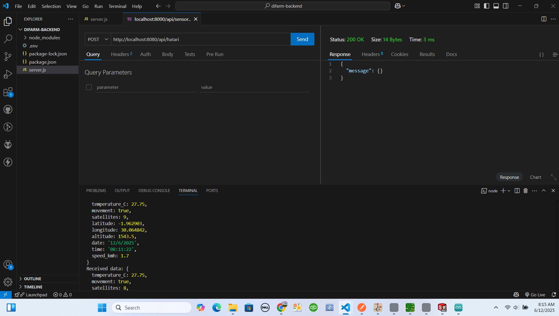
Displaying on dashboard
after testing on backend and geting api working very well, I opened the dashboard online and displayed the data collectively
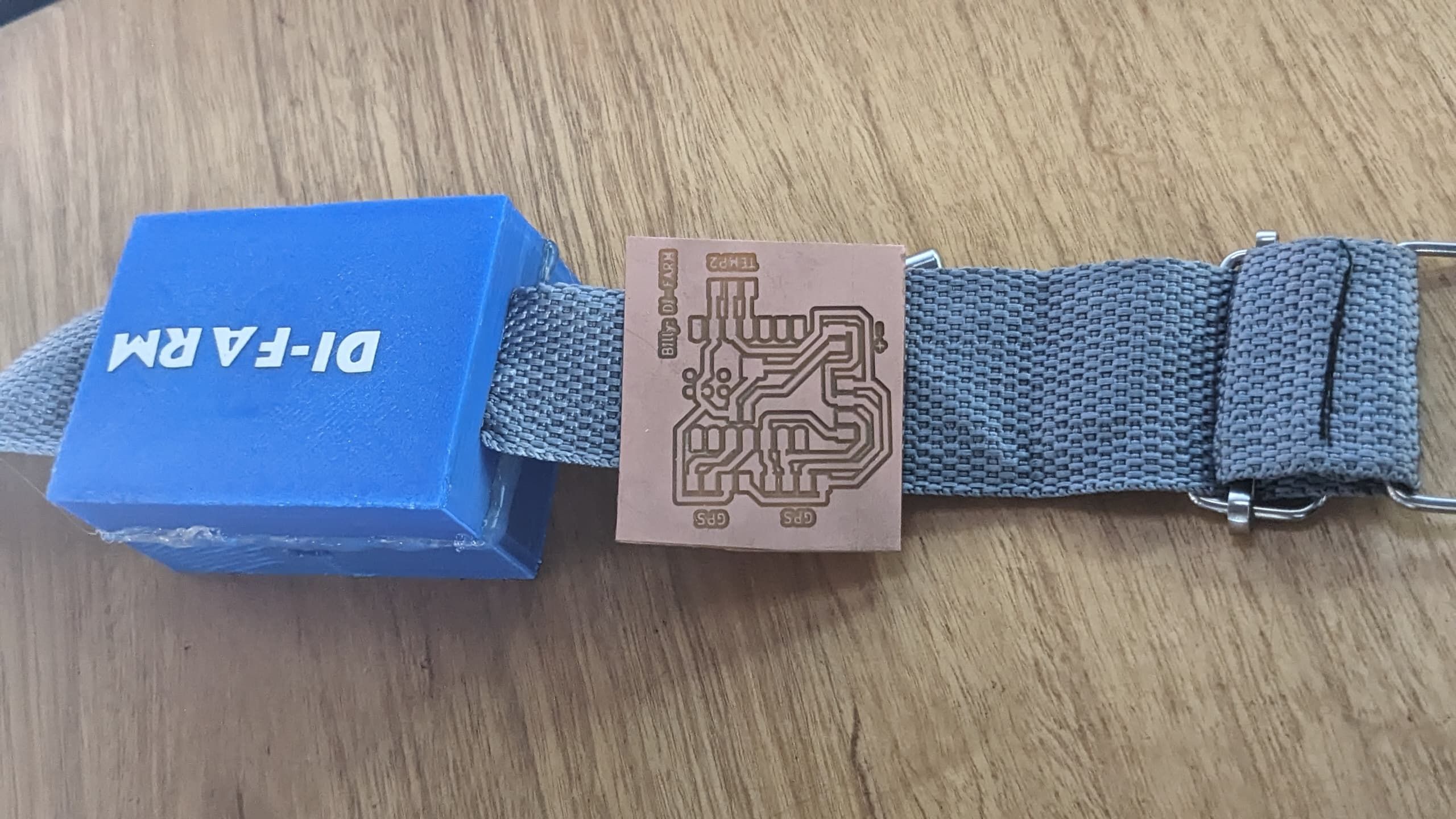
Final Mounting
I housed the electronics in the 3D-printed cover I had designed earlier, then attached it securely on a cow prototype to simulate real usage. This step helped me confirm durability and functionality.
Outcomes of Integration
- Data flows smoothly from sensors to dashboard
- Wireless communication (Wi-Fi) is stable
- All sensor readings are accurate and updated in real-time
This integration step confirmed that the DI-FARM system is functional and deployable, meeting my goal of tracking cow health and location remotely and in real-time.