5. 3D Printing and Scanning
This week focused on 3D printing and scanning, exploring additive manufacturing techniques and capturing real-world objects in digital form.
Part 1: 3D Printing
Understanding the basics
What is 3d Printing?
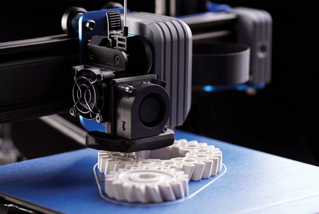
3D printing is a process of creating physical objects from a digital design by adding material layer by layer. Unlike traditional manufacturing methods, which often involve cutting or molding materials, 3D printing builds objects from the ground up, making it a highly efficient and flexible way to create complex shapes.
G-code
G-code is the language that 3D printers understand to create an object. It is a set of instructions that tells the printer where to move, how fast to go, how much material to extrude, and at what temperature to operate. Each line of G-code controls a specific action, such as moving the print head to a certain position or adjusting the speed of material extrusion.
How to create a G-code?
To create a G-code file for 3D printing, you first need a 3D model in a format like STL. This model is then processed using slicing software such as Cura, PrusaSlicer, or Simplify3D. The slicer analyzes the model and divides it into thin horizontal layers. It then generates step-by-step instructions that tell the printer what to do. Once the slicing is complete, the software exports a G-code file, which can be transferred to the 3D printer using an SD card, USB, or direct connection. The printer then reads the G-code and follows the instructions to build the object layer by layer.
Different 3D Printing Technologies
- Fused Deposition Modeling (FDM)
FDM is the most widely used 3D printing method. It works by extruding heated filament (usually plastic like PLA, ABS, or PETG) through a nozzle onto a build platform. The material is deposited layer by layer, solidifying as it cools. FDM is cost-effective and ideal for prototyping but may have visible layer lines and lower resolution compared to other methods.

- Stereolithography (SLA)
SLA uses a laser or UV light to cure liquid resin layer by layer in a vat. This process results in high-detail prints with smooth surfaces, making it ideal for jewelry, dental models, and miniatures. However, SLA requires post-processing, such as washing in alcohol and UV curing, and the resins can be expensive.

- Selective Laser Sintering (SLS)
SLS uses a high-powered laser to fuse powdered materials like nylon or metal into solid objects. Since no support structures are needed (as the surrounding powder acts as support), SLS can produce complex, durable parts. It is commonly used for industrial applications but is more expensive than FDM or SLA.

Manufacturing methods
Additive v/s Subtractive
Additive manufacturing, commonly known as 3D printing, builds objects layer by layer from digital models. This process allows for the creation of complex geometries, lightweight structures, and internal cavities that are impossible or highly inefficient to achieve with traditional methods.
Subtractive manufacturing, on the other hand, involves cutting, drilling, milling, or carving material away from a solid block to create the final shape. While this method is excellent for high-precision parts and strong, dense components, it often results in significant material waste.

Group Assignment
For the group project me and Samrudhi worked togerther. We tested the Creality Ender 3 V3 KE, which is an FDM (Fused Deposition Modeling) printer. Our goal? To see how well this printer handles tricky design features and to understand its limits before diving into our own 3D prints.
Setting Up the Test
To put the printer through its paces, we used the Creality Print software and printed a test model from Thingiverse that checks different design rules. We kept things simple:
- Layer height: 0.2mm (a good balance between speed and detail)
- No supports: We wanted to see how well the printer could handle overhangs on its own
- PLA filament: Using the regular recommended settings
- Speed & infill: Stuck to the machine’s recommended values (no speed races this time!)
Features we are comparing:
- Overhang: An overhang is when a part of the print extends outward without anything underneath to support it. Learning: The printer did well up to a certain angle, but after 45°, we noticed some sagging. This means if I want sharper overhangs, I’d need to add supports or adjust print settings.
- Bridging: Bridging tests how well the printer can print a horizontal "bridge" between two points without supports. Learning: Bridging should not be more than 12mm or it will sag.
- Sharp-corners: Sharp corners test how well the printer can stop and change direction precisely. The Ender 3 V3 KE managed this pretty well, with crisp edges.


- Scale/Dimensional Test: To check how accurately the printer follows the dimensions in the CAD design. Performing these tests helps optimize print settings, material selection, and post-processing for high-precision
Learning: The test results show that the outer dimension of the printed cube (20.02 mm) is very close to the intended 20 mm, indicating good overall accuracy. However, the inner dimension (10.02 mm) is slightly larger than expected, suggesting a minor calibration offset.

- Surface Finish: Surface finish refers to the texture and smoothness of a 3D-printed object. The quality of the finish depends on factors like layer height, print speed, cooling, and material properties.
Learning: Lower layer height (0.1mm) produce smoother surfaces, while higher layer heights (0.3mm) create more visible layer lines.

Individual Assignment
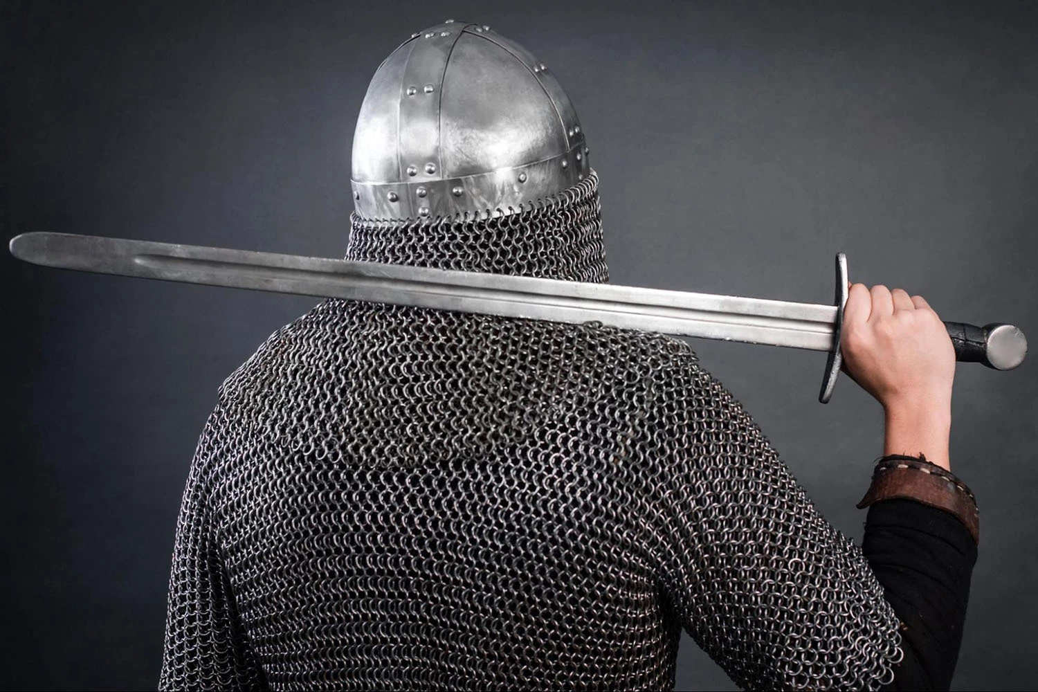
For my individual 3D printing assignment, I wanted to experiment with fabric-like 3D printing. Instead of printing a rigid object, I wanted to create something that could move, bend, and flow like fabric, but made entirely through additive manufacturing. This led me to explore Chilkhat (Marathi word for a net armour), the traditional Maratha chainmail armor used by warriors.
What is Chilkhat?
The Chilkhat was a type of chainmail or mesh armor made of interlocking metal rings or plates, designed to offer protection while maintaining flexibility. Unlike solid metal plates, this net-like armor allowed for ease of movement, making it ideal for warriors on the battlefield.

Why Fabric 3D Printing?
Fabric is typically woven or stitched together, making it impossible to create through subtractive methods like milling or laser cutting. 3D printing, however, allows for complex interlocking structures that can replicate the movement and flexibility of fabric. Chainmail-inspired designs are perfect for this because they involve small, interlinked pieces that move independently while staying connected.
Designing the fabric
I needed a repeatable unit that could link together without fusing during printing. Instead of using a simple torus (ring shape), I wanted a more fluid, organic structure that felt less rigid and more like a woven fabric. I used blender to design my interlocking net.
I started of by making a Bezier curve circle. Then by changing the mode to edit I moved up its two control points to form the shape of the chain.

Then to add volume to my shape I went to Object Data Tab, under Bevel > Round, set the Depth value to make the bezier curve a solid ring.

Then to form the interlinked pattern go to modifier tab, click Add Modifier and add an Array Modifier under the Generate category. Set the modifier count to 2 and select the Constant Offset mode and adjust the X/Y offset distance to make it intersect with the original object.

Then similarly add two more array and make sure everything is interconnected. Also set them to Constant Offset mode and set their corresponding offset on X/Y direction to twice the offset on the first array modifier. This makes every objects in the generated array have the same offset between each other.

After this go to Object mode and duplicate the chain thrice to form a pattern. Just hit Copy and then paste

Once this is done. Export your model. Go to Flie > Export > Stl.

Printing the Flexible Mesh
After finalizing the design in Fusion 360, I exported the model in STL format, which is the standard file type for 3D printing and imported the STL file into Creality Print (slicing software). I chose PLA or printing it because, much like the original metal armor, it provides structural integrity while remaining lightweight. Additionally, PLA has a smooth surface finish, which helps the links move against each other without too much friction—similar to how metal rings in historical armor were polished to prevent snagging.

Then I adjusted the print settings. The layer height was set to 0.2mm for a good balance between detail and speed. I decided to add supports to ensure that the individual links didn’t shift or fail during printing. Since the links had small overhangs and interlocked closely, supports helped maintain their shape and prevent sagging during printing.
I also used a raft instead of a skirt or brim. This provided a stable base for the print, reducing the risk of warping and ensuring that the first few layers adhered well to the print bed. The raft also made it easier to remove the delicate chainmail without damaging the individual links.


Hero Shot

Making another pattern
After this I tried exploreing another mesh pattern. This pattern was simply made by making a rectangle and subtracting it by adding two more boolean. To do this go to Modifier tag then add modifier and click on boolean


Once this is done then generate array with the same approch.

Part 2: 3D Scanning
What is 3d Scanning? 3D scanning is the process of capturing the shape and details of a physical object to create a digital 3D model. Unlike 3D modeling, where objects are designed from scratch in software, scanning helps replicate real-world objects with precision.
Shining 3D EinScan Pro HD
The Shining 3D EinScan Pro HD is a professional-grade 3D scanner known for its high resolution, speed, and versatility. It can be used in two ways: handheld mode, where you move the scanner around the object, and fixed mode, where the scanner stays in one place while the object rotates.This scanner uses structured light technology, which means it projects patterns of light onto an object and measures how they change to create a 3D model. It works well for both small and large objects and can even scan tricky surfaces like dark or shiny materials.

To operate the device you need to connect it to your computer via a USB code.
EXScan Pro
Launch EXScan Pro (Version 3.7.4.0). Link to download
This software is used with the Shining 3D EinScan Pro HD scanner. It helps to control the scanner, capture scans, and process 3D models.

Callibration
Before scanning, the Shining 3D EinScan Pro HD needs to be calibrated to ensure accuracy and precision. Calibration helps the scanner correct its positioning and depth measurements.
To calibrate, place the calibration board on a flat surface and follow the instructions in EXScan Pro. The software will guide you through different angles and positions to help the scanner adjust properly.Once calibration is complete, the scanner is ready to capture detailed and accurate 3D scans without distortion.
Note: Since my scanner was pre-calibrated, I directly proceeded with scanning without performing the calibration process.

Scan Mode
Once you open it, you’ll see different scan modes—kind of like picking the best camera mode for your photo. You can choose Handheld HD Scan for high detail, Handheld Rapid Scan for quick scans, or Fixed Scan Mode if your object is staying still.
As you scan, a live preview appears, showing which parts you’ve captured and where you need to scan more. If something looks off, you can tweak settings like brightness and resolution to get a better result.

Then you select the folder where you have to save your file

Once that is done your can set up a new project where you can select the texture, mode of alignmnet, operation mode and resolution.
- Texture: If your scanner supports color capture, you can choose whether to scan with or without texture. This means the scan can either have just the shape or also include surface colors and details.
- Mode of Alignment: The scanner needs to know how to put all the scanned pieces together. You can choose Feature Alignment (using the shape of the object), Marker Alignment (if you’re using tracking markers), or Manual Alignment (where you adjust it yourself).
- Operation Mode: This decides how much detail you want. A fast scan works quickly but might miss tiny features, while a high-detail scan takes longer but captures every little curve and edge.
- Resolution: Higher resolution means more detail, but also bigger file sizes. If you need an ultra-detailed scan, go for high resolution, but if you just want a quick model, a lower setting works fine.
Scanning a solid body
In my project i have first tried out using marker based alignment.

For doing the marker based alignment you need to stick the makers on your object. Once that is done you can start scanning. Make sure to scan to every segment and use markers as reference.

Post-processing
Once the scan is done, it’s time for some post-processing—basically, cleaning up and improving the 3D model!
- Unwatertight / Watertight: This decides whether the scan has open edges (unwatertight) or if it's fully closed (watertight) like a solid object. A watertight model is needed for 3D printing.
- Filter & Smooth: Helps reduce noise and makes the surface look cleaner by smoothing out rough areas.
- Fill Small Holes: Automatically patches up small gaps to make the model complete.
- Remove Small Floating Parts: Gets rid of tiny, disconnected pieces that aren’t part of the main scan.
- Marker Hole Filling: If you used markers for scanning, this removes their spots from the final model.

Exporting
I exported the file as STL.

Face mask
To explore 3D scanning further, I decided to scan a face. Instead of using marker alignment, where small markers are placed on the object for the scanner to track, I tried feature alignment.
Feature alignment works by recognizing natural shapes, edges, and patterns on the face rather than relying on external markers. This method made scanning smoother since I didn’t have to place or remove markers, but it also required the person to stay very still to avoid misalignment.


Me and my friend Samrudhi performed the above projects and our mentor Akhilesh Zambre helped us in it.
Scanning a plant
Issues faced
I also tried scanning a plant, but the scanner couldn’t detect it at all. Since plants have thin and irregular surfaces, the scanner struggled to find enough stable points to track.Also, because plants don’t have strong contrasts or solid edges, the scanner couldn’t properly recognize them as a scannable object.

KIRI Engine - Mobile app
Kiri Engine is a photogrammetry-based 3D scanning app that creates 3D models from a series of images. Instead of using lasers or structured light like traditional 3D scanners, Kiri Engine analyzes multiple photos taken from different angles and reconstructs the object digitally.

Scanning a plant
Since the plant wasn’t getting detected with the Shining 3D EinScan Pro HD, I decided to try a different approach using Kiri Engine, a photogrammetry-based 3D scanning app.
This method can sometimes work better for complex or organic objects, so I was curious to see if it could scan the plant.
Kiri Engine has a simple interface that lets you either click pictures directly or upload them from your gallery. A progress barshows how many images have been taken, making sure you get enough coverage. The app also gives some tips, like keeping good lighting and using a plain background, to improve the scan quality.
Note: More the picture better the outcome

After taking the photos, the app processes them to create the 3D model. A loading screen appears while it analyzes key points and stitches the images together. The app also gives feedback if some images are not clear or if more photos are needed.

Even with Kiri Engine, the scan didn’t come out perfect. The leaves were too thin and had too little texture, making it hard for the software to reconstruct their shape properly. However, it was interesting to see how different scanning methods handle different types of objects!

Scanning packaging
After testing on the plant, I decided to scan the packaging using the same app. Since packaging has a more rigid and defined structure compared to organic objects, I expected better results.
Since packaging has sharp edges and flat surfaces, I made sure to take overlapping images from different angles to help the software detect the shape accurately.
Once all the images were uploaded, Kiri Engine processed them by analyzing key points and stitching them together to create a 3D model. This step took a few minutes, depending on the number of photos and the complexity of the shape.

After processing, the 3D model was displayed on the screen. The app allows users to rotate, zoom, and inspect the scan closely. The structure of the packaging was captured well, with clean edges and a recognizable form. The crop tool allowed me to crop the unwanted parts.

Once I was happy with the scan, I exported the model. You can export it both in STL or OBJ format. You can also change the resolution of your file.

Comparison Between EinScan HD Pro and Kiri Engine
| Feature | EinScan HD Pro (Handheld) | Kiri Engine (Phone) |
|---|---|---|
| Portability | Bulky and requires setup | Fits in a pocket, easy to carry |
| Detail & Accuracy | High precision, captures fine details | Lower accuracy, struggles with thin or complex textures |
| Ease of Use | Intuitive but requires calibration | Super easy, just take photos |
| Object Suitability | Works well with rigid shapes | Best for rigid objects, struggles with thin or reflective surfaces |
| Processing Speed | Fast real-time scanning | Takes time to process images |
| Cost | Expensive, professional-grade | Free with optional paid features |
Exercise files
Below are the files for:
Image reference
FDM: Link
SLA: Link
.webp)
SLS: Link
Armour: Link