Final project

One of my idea for final project came to me one night when i was walking to the restroom in the dark hallway and i walked direct into a small chair that had been left direct in the walk path. and i hurt my litle toe. Then i thougth i maybe able to make chair(or some kind of furniture) that will activate some light and/or sound alarm if you approche it to musch in the dark. I could see that people want that kind of furnitures in there houses not only to warn them but its usefull as night light at same time.
I did some little poor sketch in this first week.

i am curently working on geting some more thougts on how to develope that project an come up with another possible final project. i will add later info about that one.
Week 2
This week i made 3d model of an chair that i am thinking to make. I used Fusion and followed instruction from copilot. and render that in Blender.
 Download .stl file
Here you can find the Fusion file
Download .stl file
Here you can find the Fusion file
here are transcript of instruction i followed from copilot:
   Sent by you:
how do i make 3d model of an small chair with out back in fusion
Copilot
Sent by Copilot:
Creating a 3D model of a small chair without a back in Fusion 360 is a great way to practice your CAD skills. Here’s a step-by-step guide to help you get started:
Step-by-Step Guide to Modeling a Small Chair Without a Back in Fusion 360
1.  Open Fusion 360:
o   Start a new design by clicking on File > New Design.
2.  Create the Seat:
o   Sketch the Seat: Click on Create Sketch and select the top plane. Use the Rectangle tool to draw a rectangle that represents the seat of the chair. For example, you might use dimensions of 40 cm by 40 cm.
o   Extrude the Seat: Finish the sketch and use the Extrude tool to give the seat thickness. For instance, extrude it to a height of 2 cm.
3.  Create the Legs:
o   Sketch the Legs: Create a new sketch on the bottom face of the seat. Draw small rectangles at each corner of the seat to represent the legs. Each leg might be 4 cm by 4 cm.
o   Extrude the Legs: Finish the sketch and use the Extrude tool to extend the legs downward. For example, extrude them to a height of 40 cm.
4.  Refine the Model:
o   Add Fillets: Use the Fillet tool to round the edges of the seat and legs for a smoother appearance. Select the edges you want to fillet and specify the radius.
o   Adjust Dimensions: Use the Modify tools to tweak the dimensions and positions of the legs if necessary.
Working plan
Link to system intergration week
I am well on the way to have this project ready. there are som few fix i need to do
- Laser cut base plare under the chair(plate that comes beetween the legs of the chair about 20-30cm obove the floor)
- print somthing for the electronic that will come on the plate in no one or under the chair.
- make final electronic or place the one i have from output week, that could be used but with out the 230V relay.
- add som led on the foot of the chair
- test and make some final adjustment.
- Finished documentasion
| Task | date finished |
|---|---|
| 1 | May 4 |
| 2 | May 11 |
| 3 and 4 | May 18 |
| 5 | May 25 |
| 6 | Jun 4 |
I wanted to change this square table to something mor modern table little bit taller and nicer , maybe a round table that will let you know with light signals if you get to close to it and at the same time serve as a night light. So one of the first thing i did was redesigne the table.
This is uniq cause its intergrated in the furniture what i have seen on the market and on nett is always haveing light that is eiter on or of not with sensor unbless it´s sold seperatly.
I am going to build this from plywood that i will cut out in the shopbot macihine, use plexiplast as decorasion cut out in the lazer cutterand support plate for the feet. and print out the plastic to housing the light, poerbank and the electronic from PETG.
Only thing that wasint made from me was the powerbank, microcontroler and the ultrasonic sensor.
 Here we can see how the table change after the project whent further.
 here are some sketch of the lightring and how it is intergrated to the table.
 Here is sketch of the lightring it self
 Then a sketch of the house for the powerbank and the electronic.
 and finaly sketch of the sensore house.
In the finalproject i will use the chair i cut out in week 07 as the furniture i call it a chair but many people call it a table causee it is little bit high to be a chair but that i did on purpose i wanted it to be something beetween a normal chair and bar chair.
 This picture shows the final look on the chair it self, but i want to add a lazer cut plesi plate beetween the legs about 30cm from the floor. then i have to #d pront somtheing for the electronic, put at least one ledstribe on the inside of the leg.
Thats all i have to do i think, if time will allow i will add lights to all the feets and sensor to at least to direction.
This picture shows the final look on the chair it self, but i want to add a lazer cut plesi plate beetween the legs about 30cm from the floor. then i have to #d pront somtheing for the electronic, put at least one ledstribe on the inside of the leg.
Thats all i have to do i think, if time will allow i will add lights to all the feets and sensor to at least to direction.
Here is the lazer cut plexiplast that i made for the chair, orginali i was thinking this as a CHair but this works better as a table so from now on i call it a table.

And picture of the Table with that plexi installed.

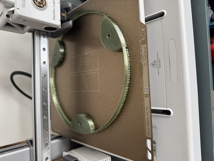
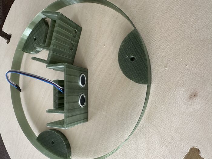
In this pictures we see that light ring that the LED light will be mounted on being printed, and on the othe r we see the ring ready and the house for the ultrasonic sensor.
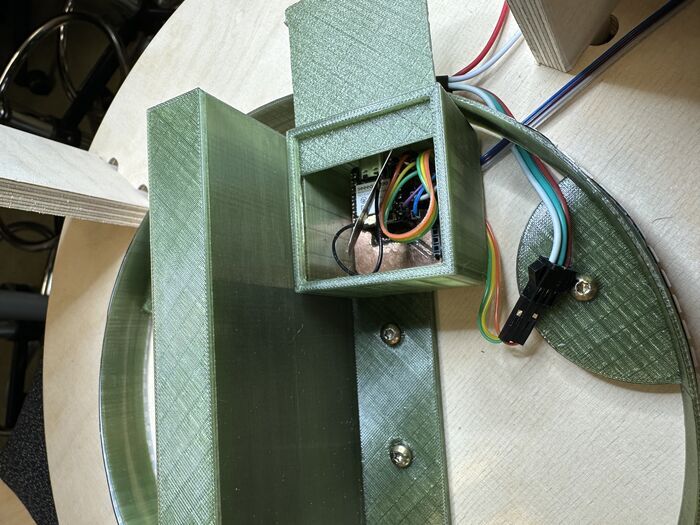
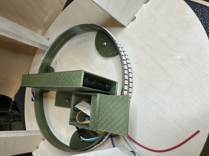
Here we see the house for the powerbank and the electronic and the it´s a picture of all assembled
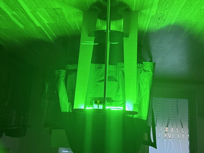
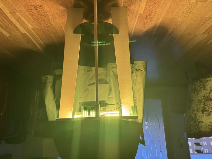
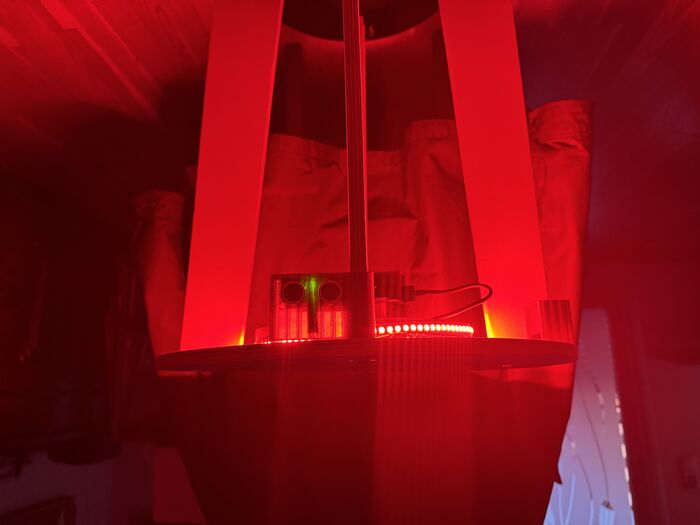
These three pictures show the lights on the table.
- Green on 100cm
- Yellow at 65cm
- Red at 40cm
Electronic
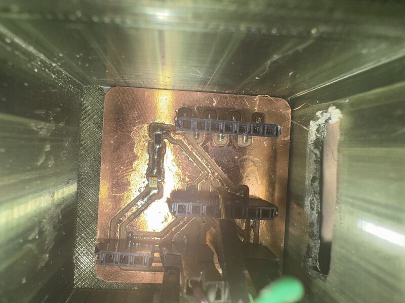
I made the electronic in Kicad and then i milled it out on the Roland mill. This was very simple circut i had to make space for thee XIAO ESP32C3 on the board and have connectors for the LED, Ultrasonic sensor 3 pin and i also added connectors for PIR sensor but i didint use those connectors.
I did uby and use these components

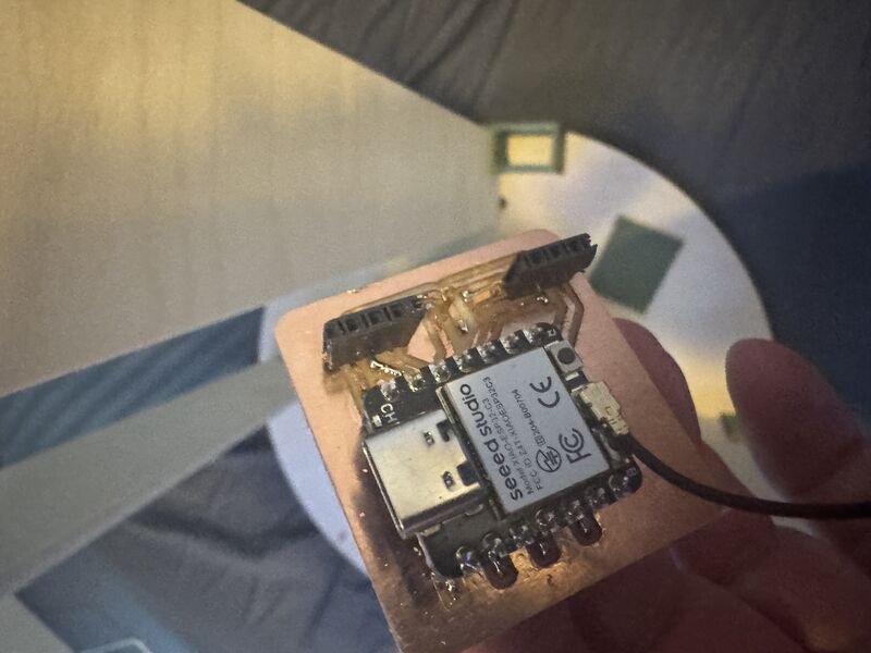
This is the XIAO SPEEED ESP32c3 that i used
This microchip is very power full it has both 3,3V and 5V out and 11 input/output pins i did use pin D8 to D10(see the pin out diagram) in this projec as the 5V to feed the electronic componenets

The ultrasonic sensor i used
This Ultrasonic sensor has three pins one for the 5V anoteher for the Ground and then one pin that is both echo and the trigger pin

led light i used this led ligt takes 5V in and is controled by data input from the ESP32C3

Pin out diagram
I did connect the light to and the sensorse to 5 volt and use pin D10 as output to the light to controle the light. D9 is connect to the trigger/echo pinn to the ultrasonic sensor and D8 to signal pin on the PIR sensor.
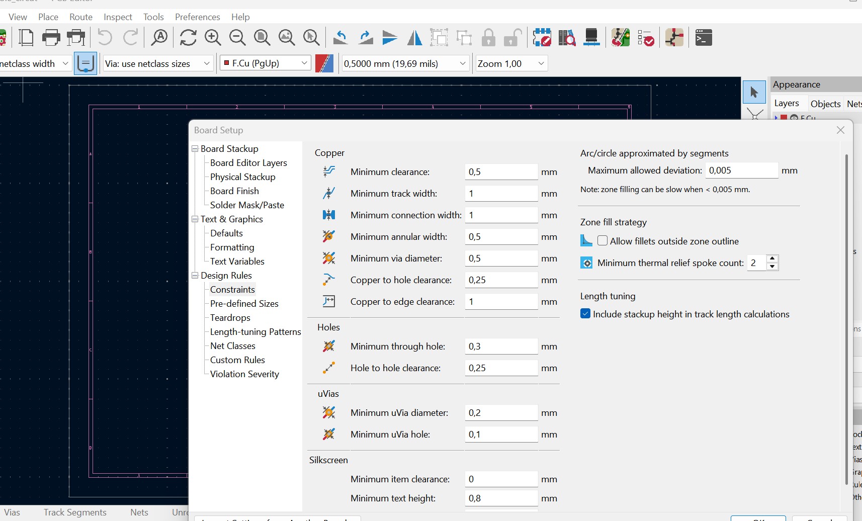
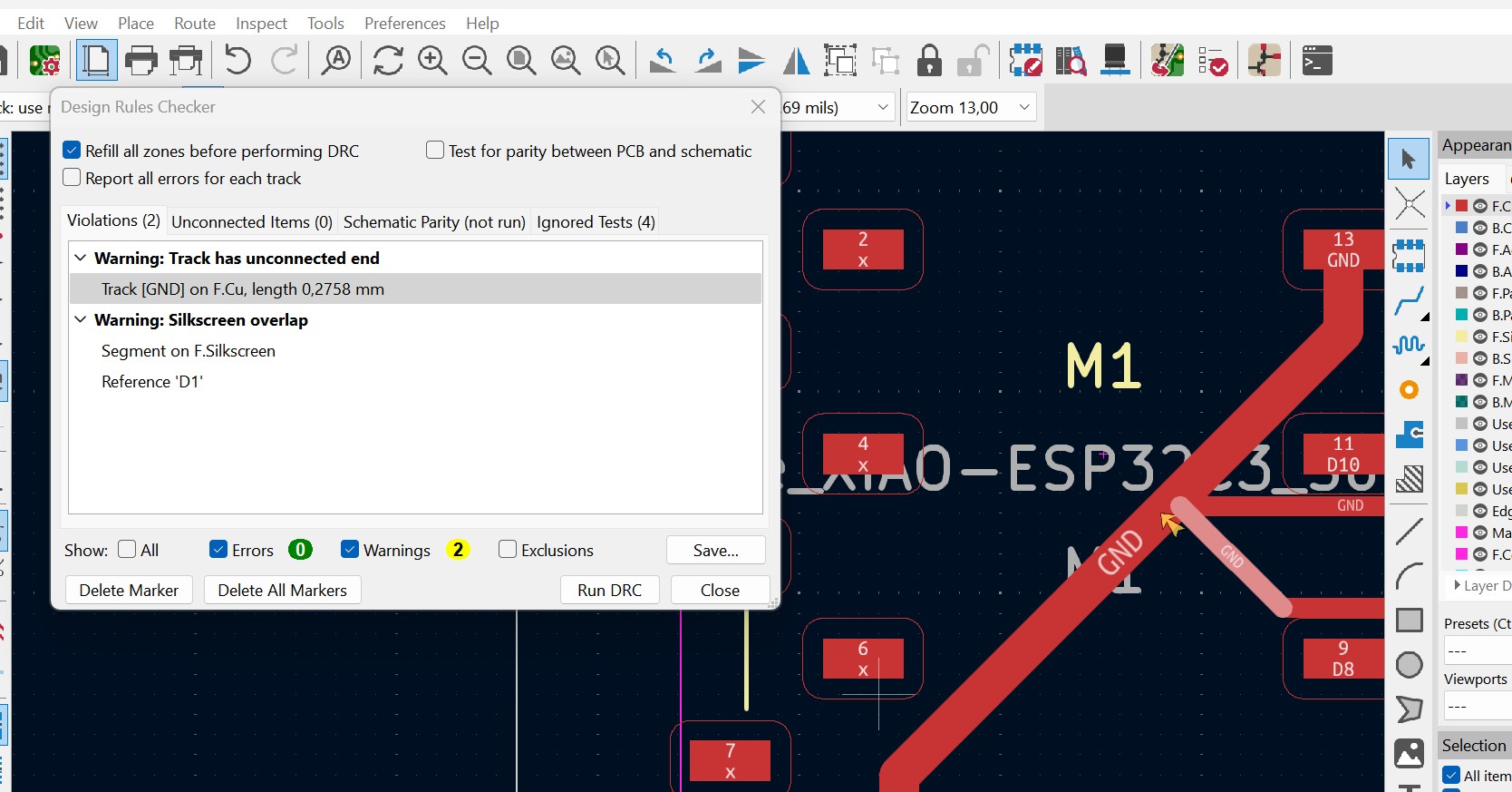
Here on these two picture we see the setting of the design rules and the result from the designe rule checker.
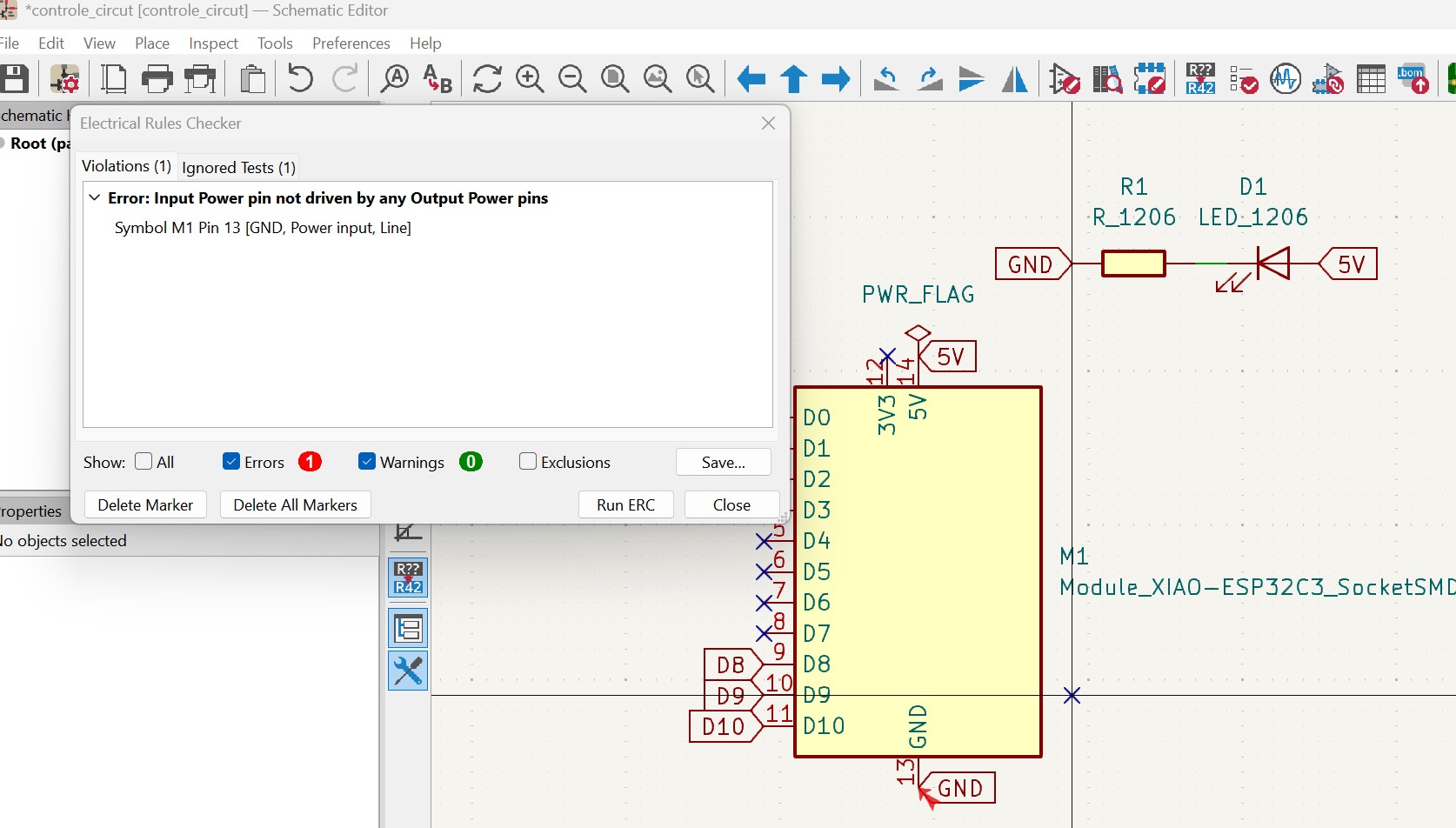
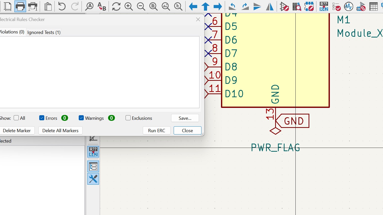
Here we see the electrical rule checker first with errors and then after the errors have been fixed.
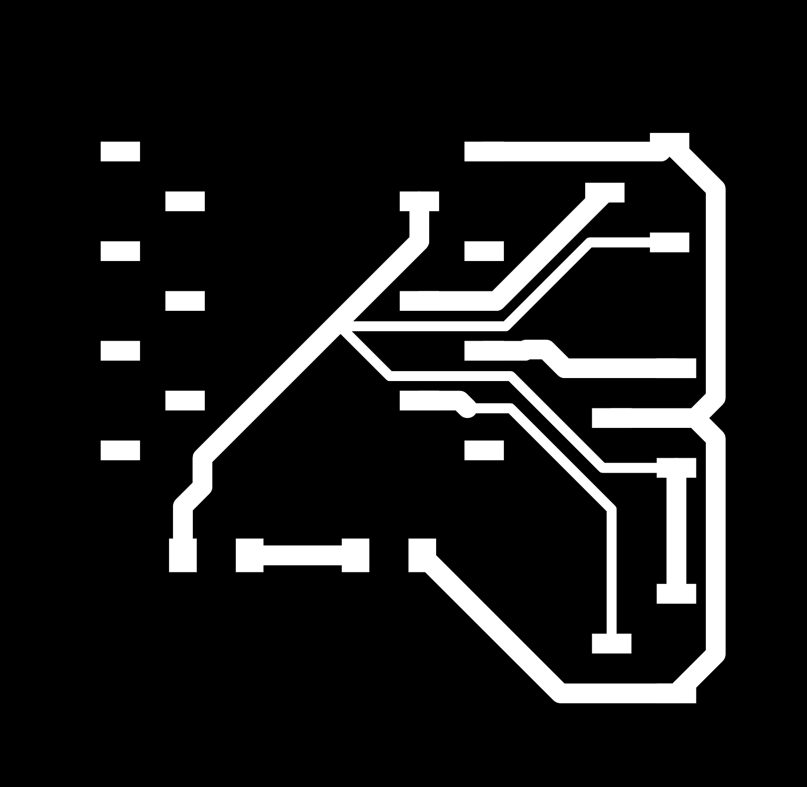
Then here we see the traces and theb the elecrical circut ready with and with out microcontroler.
I only had to make this circut once and it worked perfectly.
This video shows the electronic mounted and connected
The code
This is the code i made whit a ltle help from Copilot to fix the code i made
This code uses an ultrasonic sensor to measure distance and changes the color of an LED strip based on the measured distance. The averaging of distance measurements helps to stabilize the readings and reduce flickering of the LEDs.
#include <Adafruit_NeoPixel.h>

#define PIN D10 // Pin connected to the DIN of WS2812B
#define NUMPIXELS 140 // Number of LEDs in the strip
#define TRIG_ECHO_PIN D9 // Pin connected to the Trig/Echo pin of the ultrasonic sensor

Adafruit_NeoPixel strip = Adafruit_NeoPixel(NUMPIXELS, PIN, NEO_GRB + NEO_KHZ800);

void setup() {
  strip.begin();
  strip.show(); // Initialize all pixels to 'off'
  pinMode(TRIG_ECHO_PIN, OUTPUT);
}

void loop() {
  long duration, distance;
  pinMode(TRIG_ECHO_PIN, OUTPUT);
  digitalWrite(TRIG_ECHO_PIN, LOW);
  delayMicroseconds(2);
  digitalWrite(TRIG_ECHO_PIN, HIGH);
  delayMicroseconds(10);
  digitalWrite(TRIG_ECHO_PIN, LOW);
  pinMode(TRIG_ECHO_PIN, INPUT);
  duration = pulseIn(TRIG_ECHO_PIN, HIGH);
  distance = (duration / 2) / 29.1; // Convert to distance in cm


  if (distance <= 40) {
    setStripColor(strip.Color(255, 0, 0)); // Red color
  } else if (distance <= 65) {
    setStripColor(strip.Color(255, 255, 0)); // Yellow color
  } else if (distance <= 100) {
    setStripColor(strip.Color(0, 255, 0)); // Green color
  } else {
    setStripColor(strip.Color(0, 0, 0)); // Turn off LEDs
  }
  delay(500);
}

void setStripColor(uint32_t color) {
  for(int i=0; i<strip.numPixels(); i++) {
    strip.setPixelColor(i, color);
  }
  strip.show();
}
Simple but works fine
#include <Adafruit_NeoPixel.h>

#define PIN D10 // Pin connected to the DIN of WS2812B
#define NUMPIXELS 140 // Number of LEDs in the strip
#define TRIG_ECHO_PIN D9 // Pin connected to the Trig/Echo pin of the ultrasonic sensor

Adafruit_NeoPixel strip = Adafruit_NeoPixel(NUMPIXELS, PIN, NEO_GRB + NEO_KHZ800);
This part is defining the librarys that we use and defingin the pins and telling how many leds there is on the stribe and in the end what kind of stribe.
void setup() {
  strip.begin();
  strip.show(); // Initialize all pixels to 'off'
  pinMode(TRIG_ECHO_PIN, OUTPUT);
}
- strip.begin();: Initializes the NeoPixel strip.
- strip.show();: Ensures all pixels are turned off initially.
- pinMode(TRIG_ECHO_PIN, OUTPUT);: Sets the ultrasonic sensor pin as an output.
void loop() {
  long duration, distance;
  pinMode(TRIG_ECHO_PIN, OUTPUT);
  digitalWrite(TRIG_ECHO_PIN, LOW);
  delayMicroseconds(2);
  digitalWrite(TRIG_ECHO_PIN, HIGH);
  delayMicroseconds(10);
  digitalWrite(TRIG_ECHO_PIN, LOW);
  pinMode(TRIG_ECHO_PIN, INPUT);
  duration = pulseIn(TRIG_ECHO_PIN, HIGH);
  distance = (duration / 2) / 29.1; // Convert to distance in cm


  if (distance <= 40) {
    setStripColor(strip.Color(255, 0, 0)); // Red color
  } else if (distance <= 65) {
    setStripColor(strip.Color(255, 255, 0)); // Yellow color
  } else if (distance <= 100) {
    setStripColor(strip.Color(0, 255, 0)); // Green color
  } else {
    setStripColor(strip.Color(0, 0, 0)); // Turn off LEDs
  }
  delay(500);
}
- Measures the distance using the ultrasonic sensor by sending a pulse and measuring the time it takes to return.
- Takes multiple distance measurements (NUM_SAMPLES) and averages them to reduce fluctuations.
- Determines the color of the LED strip based on the averaged distance:
- Red if the distance is less than or equal to 40 cm.
- Yellow if the distance is between 41 and 65 cm.
- Green if the distance is between 66 and 100 cm.
- Turns off the LEDs if the distance is greater than 210 cm.
- Updates the LED strip color only if the new color is different from the current color.
- Adds a delay of 500 milliseconds before the next measurement.
void setStripColor(uint32_t color) {
  for(int i=0; i<strip.numPixels(); i++) {
    strip.setPixelColor(i, color);
  }
  strip.show();
setStripColor Function:
- Sets the color of all LEDs in the strip to the specified color.
- Calls strip.show(); to update the strip with the new co
System Intergration
I did make a workflow system intergration plan that look like this.

This workflow show what is suppose to connect to geather and what parts are going to depends on each other for the project.
Then after i did this i was not really happy with it so i opend chat gpt and ask him to makeme system intergration slide.
Here is the text i gave chatgpt
make me system intergration slide of a table that will interact to movement using ultrasonic sensor and xiao esp32c3 if you walk to the table then it will turn on green light then if closer it will get yellow and then red. have to make the whole system
and this was the outcome

After assembly everythig and program the system i tested it and it work fine exept the light was not stable enough so i added some avrage sistanse to the code and let the microcontroler read the color of the light before changing the color.
What will it do
This is a smart table with ultrasonic sensor and a led light strib that will let you know your distance to the table with three different colors. - Green 100cm - Yellow 65 cm - Red 40 cm - The meaning is that you will see the table in the dark, this is also a night light
Who has done what before hands?
Searching the net and fabacademy site i didint find anything that was exacly the same thing, i found that people have done many things whit table but never turn them direct into nightlight whit warning system. Then i found speaker table by Anubhav Jain.
Quick searce on the nett reveled there is alot of furnitur on the market with inbuilt lights but none i found have sensor to activate the lights.
I think it´s very interestet that there are not more furniture on the market haveing intergrated night light with sensor.
On the internet it´s easy to find lights with sensors it´s all kind of lights and almost all light producer in the world has some kind of light that has sensor, tabel light, celling light and lights to intergrate in other things.
WHat will i designe?
i will designe a table that has intergrated night/warning light that let you know if you get to close, it´s speciali thought that it will warn u and make it self visible if it´s dark area.
the system wil work like this if ýou come in the range of 100cn light will turn green when you are in the range of 55cm light will turn yellow and when you are in the range of 45 cm the light gets red.
- Designe a table
- Design the electronic
- Design the the seat for the light
- Design the house for the sensor
- Desigen the house for the electronic and the poewer bank
What sources did i use
In ths project i used sources like - XIAO wiki - Kicad - FUSION 360 - Copilot to fix the code i made
What material and components were used
BOM
| Section | Item | Description | Qty | Datasheet/links/notes | Estimated cost |
|---|---|---|---|---|---|
| PCB Board | |||||
| Seeed XIAOESP32C3 | Microcontroler with bluethooth and Wi-fi connection | 1 | XIAO ESP32C3 Wiki | $4,99 | |
| Powerbank | Rechargable powerbank(not found yet) | 1 | $5,99 | ||
| 3D printed houseing | Box/hous e to protect electronics | 1 | printed in translucent PETG | $5,99 | |
| DYP-HE007TX | Ultrasonic distance measuring sensor | 1-4 | In first edition i will use 1 sensor but in later spirals i will add more sensors | $10 | |
| LED RGB | 5V LED stribe with RGB | 1M | Bought from Amason LED stirbe | $11,99 | |
| pinsocket | |||||
| Pinsocket | |||||
| Table | |||||
| Plywood | 12mm plywood or wood at any type | 1m2 | Found in nearest hardwae store | $? | |
| Plexiplast | dark or any other color | 0,5m2 | $? |
what part and system will be made?
I will make the table from some 12mm ply wood in the shopbot machine,i will then make the electronic design, mill and solder, i will use xiao ESP32c3 that is factory made and add him to the circut with sockets, the sensor i will by and the powerbank , then i will make the bottom plate for the table in the laser cutter from dark plexi. and print out in PETG the house for electronic, sensor and the ring for the light. light stribe is bought.
What processos will be used?
For the wood i will use the shopbot and cutt out the table. For the electronig i will mill out the circut either with the Roland mill or the lunyee mill. For the printing i will print all things in my Bambulab A1 printer FOr the plexi plast i will cut that out in the lazer cutter
What question need to be answeard?
- The bigest question is what sensor is best to use?
- How ti intergrate all pieces to gether?
- In my project i got one question from people that i wasint expecting every one asking if what i started with as a chair was a table, so in the end i called it table. But it still can be used as i high chair.
- What processor to use?
What has worked? What hasn´t?
This was very smoth project, maybe not complicated enough.
But however i had few problems with the sensor, when i had program the system and teste the light wasint stable enough it was flickering so i needed to add some thing to the code like let the sytem read the color of the light before change color, and to read avreage distance and use that distans to controle the color.
Designing the 3d printet parts only problem i had was the house for the sensor was to small, so i had to redesing that.
How will it be evaluated?
This project will be evaluated after how its work, that is if it work as intended, and of course also by its look. And how it was intergrated.
In this project i onluy used 5 screws 3 to fasten the bracket for the ligt and 2 for the electronic housing.
And after testing then it seams like this is working nicely.
What are the implication
In this project the ultrasonic sensor is measuring distance and if distance is an specified distansce it wil turn the light on in various colors after distance lenght.
And here is a picture of the final produt

Here is a video of the final prouduct working
License
This work is done under CC-BY-NC-SA 4.0 license
- Allows others to remix, adapt, and build upon the work non-commercially, as long as they credit the creator and license their new creations under the identical terms.

Creative Commons
Creative Commons is an international nonprofit organization that empowers people to grow and sustain the thriving commons of shared knowledge and culture we need to address the world’s most pressing challenges and create a brighter future for all.
This work is done under CC-BY-NC-SA 4.0 license.
- CC = Creative common
- BY = Credit must be given to you, the creator.
- NC =Only noncommercial use of your work is permitted. Noncommercial means not primarily intended for or directed towards commercial advantage or monetary compensation.
- SA = Adaptations must be shared under the same terms.
Design Files
- Table .dxf
- Table .f3d
- Table vcarf
- Table foot .DXF
- Table lightring .f3d
- Table lightring .stl
- Table sensor house .f3d
- Table sensor house .stl
- Table electronic housing .f3d
- Table electronig housing .stl
- Table lock for electronic .f3d
- Table lock for electronic .stl
- Table bottom plate .DXF
- Kicad files
- C++ code for the esp32c3