14. Interface and Application Programming
This week assignment
Task: Interface and Application Programming - Group assignment:
- Compare as many tool options as possible.
- Document your work on the group work page and reflect on your individual page what you learned.
-
Individual assignment
-
Write an application for the embedded board that you made. that interfaces a user with an input and/or output device(s)
Progress
-
Grupp assignment
- [ ]- Compare as many tool options as posible.
- Document your work on the group work page and reflect on your induvidial page what u learned.
-
Induvidual assignment
- Write an application for the embedded board that you made. that interfaces a user with an input and/or output device(s)
Research
In the process of doing the research for this assignment i found out that there are many ways to do application interface. normaly called API (Application programming interface). I knew little bit before what it is.
Interface define how different components of a system interact to each other when using user interface to contrrole them or reading data.
APIs is developement envirement that enables developers to intergrate functionalities from other applications.
The main difference beetween API and interface is that API is a set of rules for comunication, and theintefaces use those rules too interact to each others.
Good site fore information about API are the Geeksforgeeks. Then my instructor point me to this site abot how to put up a server on ESP32
WHat did i learn from the group assignment.
What did i learn on the group assignment, well it´s alot of user interfaces to use we have the web server versions that i used in my program, it´s also alot of other apps and interfaces to remotly control electronics. in my assignment i used the web server thatallow you to controle the circut as long as your on the same Wi-fi. there are also other apps that let you remotly control the circut from another networks. From PC, phone and other devices. you can show both input and outputs even show some realtime diagrams like heat over some time or current used by the circut over some time. It´s almost nothing you cant see,or control by this kinde of User Interface as long as you have circut that can do what you want to control or show.
programming the interface for the embadded circut
I wanted to use the little board i did make with 2 lEDs and controle them from the intefrface application, i decided that i am going to use the ESP32C3 and sett up a server on the micro proccessor and use Cöö and arduino IDE dor the work.
I found some information on the site randomtnerdtutorials that my instructor Andri pointed me to.
That site has very good information about how to put up web server on ESP32. and there is also a C++ code that works and very good explaneasion of how the code works. i am going tu use that code and personalize it little bit.
Original code.
/*********
  Rui Santos
  Complete project details at http://randomnerdtutorials.com
*********/

// Load Wi-Fi library
#include <WiFi.h>

// Replace with your network credentials
const char* ssid = "REPLACE_WITH_YOUR_SSID";
const char* password = "REPLACE_WITH_YOUR_PASSWORD";

// Set web server port number to 80
WiFiServer server(80);

// Variable to store the HTTP request
String header;

// Auxiliar variables to store the current output state
String output26State = "off";
String output27State = "off";

// Assign output variables to GPIO pins
const int output26 = 26;
const int output27 = 27;

// Current time
unsigned long currentTime = millis();
// Previous time
unsigned long previousTime = 0;
// Define timeout time in milliseconds (example: 2000ms = 2s)
const long timeoutTime = 2000;

void setup() {
  Serial.begin(115200);
  // Initialize the output variables as outputs
  pinMode(output26, OUTPUT);
  pinMode(output27, OUTPUT);
  // Set outputs to LOW
  digitalWrite(output26, LOW);
  digitalWrite(output27, LOW);

  // Connect to Wi-Fi network with SSID and password
  Serial.print("Connecting to ");
  Serial.println(ssid);
  WiFi.begin(ssid, password);
  while (WiFi.status() != WL_CONNECTED) {
    delay(500);
    Serial.print(".");
  }
  // Print local IP address and start web server
  Serial.println("");
  Serial.println("WiFi connected.");
  Serial.println("IP address: ");
  Serial.println(WiFi.localIP());
  server.begin();
}

void loop(){
  WiFiClient client = server.available();   // Listen for incoming clients

  if (client) {                             // If a new client connects,
    currentTime = millis();
    previousTime = currentTime;
    Serial.println("New Client.");          // print a message out in the serial port
    String currentLine = "";                // make a String to hold incoming data from the client
    while (client.connected() && currentTime - previousTime <= timeoutTime) {  // loop while the client's connected
      currentTime = millis();
      if (client.available()) {             // if there's bytes to read from the client,
        char c = client.read();             // read a byte, then
        Serial.write(c);                    // print it out the serial monitor
        header += c;
        if (c == '\n') {                    // if the byte is a newline character
          // if the current line is blank, you got two newline characters in a row.
          // that's the end of the client HTTP request, so send a response:
          if (currentLine.length() == 0) {
            // HTTP headers always start with a response code (e.g. HTTP/1.1 200 OK)
            // and a content-type so the client knows what's coming, then a blank line:
            client.println("HTTP/1.1 200 OK");
            client.println("Content-type:text/html");
            client.println("Connection: close");
            client.println();

            // turns the GPIOs on and off
            if (header.indexOf("GET /26/on") >= 0) {
              Serial.println("GPIO 26 on");
              output26State = "on";
              digitalWrite(output26, HIGH);
            } else if (header.indexOf("GET /26/off") >= 0) {
              Serial.println("GPIO 26 off");
              output26State = "off";
              digitalWrite(output26, LOW);
            } else if (header.indexOf("GET /27/on") >= 0) {
              Serial.println("GPIO 27 on");
              output27State = "on";
              digitalWrite(output27, HIGH);
            } else if (header.indexOf("GET /27/off") >= 0) {
              Serial.println("GPIO 27 off");
              output27State = "off";
              digitalWrite(output27, LOW);
            }

            // Display the HTML web page
            client.println("<!DOCTYPE html><html>");
            client.println("<head><meta name=\"viewport\" content=\"width=device-width, initial-scale=1\">");
            client.println("<link rel=\"icon\" href=\"data:,\">");
            // CSS to style the on/off buttons
            // Feel free to change the background-color and font-size attributes to fit your preferences
            client.println("<style>html { font-family: Helvetica; display: inline-block; margin: 0px auto; text-align: center;}");
            client.println(".button { background-color: #4CAF50; border: none; color: white; padding: 16px 40px;");
            client.println("text-decoration: none; font-size: 30px; margin: 2px; cursor: pointer;}");
            client.println(".button2 {background-color: #555555;}</style></head>");

            // Web Page Heading
            client.println("<body><h1>ESP32 Web Server</h1>");

            // Display current state, and ON/OFF buttons for GPIO 26
            client.println("<p>GPIO 26 - State " + output26State + "</p>");
            // If the output26State is off, it displays the ON button
            if (output26State=="off") {
              client.println("<p><a href=\"/26/on\"><button class=\"button\">ON</button></a></p>");
            } else {
              client.println("<p><a href=\"/26/off\"><button class=\"button button2\">OFF</button></a></p>");
            }

            // Display current state, and ON/OFF buttons for GPIO 27
            client.println("<p>GPIO 27 - State " + output27State + "</p>");
            // If the output27State is off, it displays the ON button
            if (output27State=="off") {
              client.println("<p><a href=\"/27/on\"><button class=\"button\">ON</button></a></p>");
            } else {
              client.println("<p><a href=\"/27/off\"><button class=\"button button2\">OFF</button></a></p>");
            }
            client.println("</body></html>");

            // The HTTP response ends with another blank line
            client.println();
            // Break out of the while loop
            break;
          } else { // if you got a newline, then clear currentLine
            currentLine = "";
          }
        } else if (c != '\r') {  // if you got anything else but a carriage return character,
          currentLine += c;      // add it to the end of the currentLine
        }
      }
    }
    // Clear the header variable
    header = "";
    // Close the connection
    client.stop();
    Serial.println("Client disconnected.");
    Serial.println("");
  }
}
Breaking down the code.
In this section i am goin to explain part of the code. Mostly the part i am going to change to personalize the web server.
First its the part where u need to set your network credentail,
// Replace with your network credentials
const char* ssid     = "REPLACE_WITH_YOUR_SSID";
const char* password = "REPLACE_WITH_YOUR_PASSWORD";
in this part of the code we need to put in our SSid and password. That is the total minimum you need to do if you make the board like its done in that tutorial, I how ever are going to make more changes to the code so it will work with my circut and try to costumade the code for my project.
Next stepp would be make sure i have the right pins assigned ass it is connected.
const int output26 = 26;
const int output27 = 27;
I will have to change it to this, cause that is the numbers on the XIOA seeed 32C3 im using.
const int output26 = D1;
const int output27 = D2;

Here in this part i need to change all the number 26 to D1 and all the 27 to D2.
// turns the GPIOs on and off
if (header.indexOf("GET /26/on") >= 0) {
  Serial.println("GPIO 26 on");
  output26State = "on";
  digitalWrite(output26, HIGH);
} else if (header.indexOf("GET /26/off") >= 0) {
  Serial.println("GPIO 26 off");
  output26State = "off";
  digitalWrite(output26, LOW);
} else if (header.indexOf("GET /27/on") >= 0) {
  Serial.println("GPIO 27 on");
  output27State = "on";
  digitalWrite(output27, HIGH);
} else if (header.indexOf("GET /27/off") >= 0) {
  Serial.println("GPIO 27 off");
  output27State = "off";
  digitalWrite(output27, LOW);
}
It will be looking like this after changes
// turns the GPIOs on and off
if (header.indexOf("GET /D1/on") >= 0) {
  Serial.println("GPIO D1 on");
  output26State = "on";
  digitalWrite(output26, HIGH);
} else if (header.indexOf("GET /D1/off") >= 0) {
  Serial.println("GPIO D1 off");
  output26State = "off";
  digitalWrite(output26, LOW);
} else if (header.indexOf("GET /D2/on") >= 0) {
  Serial.println("GPIO D2 on");
  output27State = "on";
  digitalWrite(output27, HIGH);
} else if (header.indexOf("GET /D1/off") >= 0) {
  Serial.println("GPIO D1 off");
  output27State = "off";
  digitalWrite(output27, LOW);
}
Here i did not change the numbers were it says ouput26 or 27 cause it is done in the first section were i change those variabels to D1 and D2 so i wont have to change that every were intthe code.
Styling the web page.
In this part i am going to point out some part of the code that is used to style the web site and what it dose.
Here we can change the fonts if we want in this code we are using helvetica fonts.
client.println("<style>html { font-family: Helvetica; display: inline-block; margin: 0px auto; text-align: center;}");
Here we can change the button, background color, coæer, borders and fonts.
client.println(".button { background-color: #4CAF50; border: none; color: white; padding: 16px 40px;");
client.println("text-decoration: none; font-size: 30px; margin: 2px; cursor: pointer;}");
If we want to have the second button in different color we can do it in this line.
client.println(".button2 {background-color: #555555;}</style></head>");
Here we can then set the web page Heading the name on the page.
// Web Page Heading
client.println("<h1>Evert´s light show</h1>");
That was the main part of the code that is important to understand to do relevant changes.
Here is a link to page with html color codes
Here is the code here is the orginal source code
To be able to program the microcontroler i need to connect the ESP32 to the computer using Arduino IDE.

After the code has been change then its time to uploading the code, find and open the server


Then it´s time to check if it works.
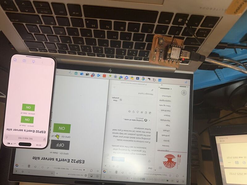
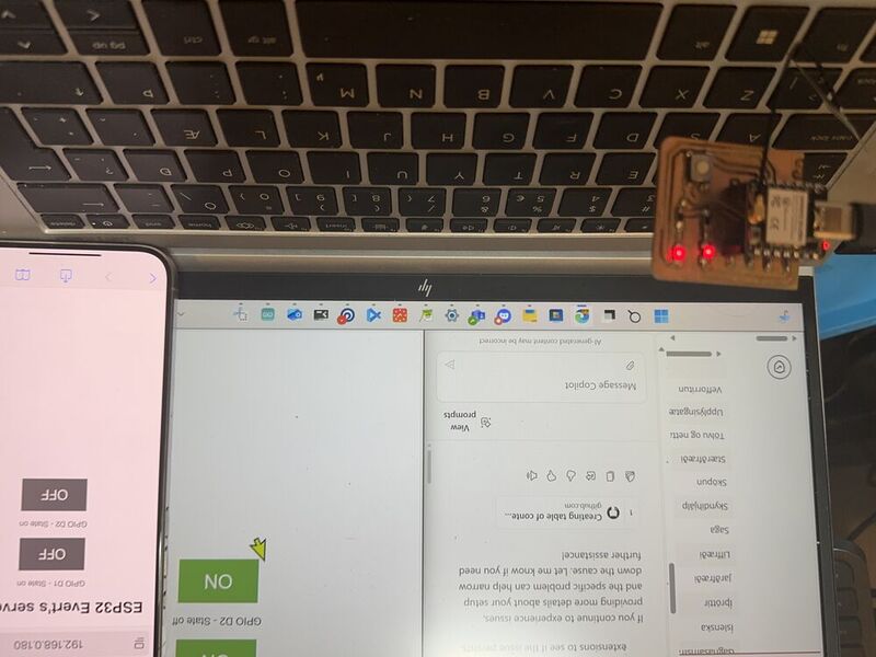
In the previous pictures you can see the color of the buttons, here is one picture after i change the color of the buttons.

Here are two video showing that it works.
video code
video code
Web serial
I did also try web serial connection that takes input from the button and interact to the ESP32 i had to make code in chat gpt
both for the ESP32C3 and the html code for chrome.
here are the files for this project:
- Chat gpt promt
- ESP32 code
- Html code
What i need: - circut with led and button - ESP32C3 - Chrome browser - usb cord - Arduino IDE
Here is the final code i used for the ESP32C3
#define LED_PIN     2
#define BUTTON_PIN  1

bool ledState = false;
bool lastButtonState = HIGH;

void setup() {
  Serial.begin(115200);
  pinMode(LED_PIN, OUTPUT);
  pinMode(BUTTON_PIN, INPUT_PULLUP);
  digitalWrite(LED_PIN, ledState);

  Serial.println("ESP32 ready. Use WebSerial or press the button to toggle LED.");
}

void loop() {
  // --- Handle WebSerial input ---
  if (Serial.available()) {
    String cmd = Serial.readStringUntil('\n');
    cmd.trim();

    if (cmd == "on") {
      ledState = true;
      Serial.println("LED turned ON (via WebSerial)");
    } else if (cmd == "off") {
      ledState = false;
      Serial.println("LED turned OFF (via WebSerial)");
    } else if (cmd == "toggle") {
      ledState = !ledState;
      Serial.print("LED toggled to ");
      Serial.println(ledState ? "ON" : "OFF");
    } else {
      Serial.println("Unknown command");
    }
    digitalWrite(LED_PIN, ledState);
  }

  // --- Handle button press ---
  bool buttonState = digitalRead(BUTTON_PIN);

  if (lastButtonState == HIGH && buttonState == LOW) {
    // Button just got pressed
    ledState = !ledState;
    digitalWrite(LED_PIN, ledState);
    Serial.print("LED toggled to ");
    Serial.println(ledState ? "ON (via button)" : "OFF (via button)");
    delay(200); // Debounce
  }

  lastButtonState = buttonState;
}
And here is the .html code i used for the web serial server in chrome
<!DOCTYPE html>
<html>
<head>
  <title>ESP32 LED Toggle</title>
</head>
<body>
  <h1>ESP32 LED Control via WebSerial</h1>
  <button onclick="connect()">🔌 Connect to ESP32</button><br><br>

  <button onclick="sendCommand('on')">💡 LED ON</button>
  <button onclick="sendCommand('off')">💡 LED OFF</button>
  <button onclick="sendCommand('toggle')">🔁 Toggle LED</button>

  <h3>Status:</h3>
  <pre id="log" style="background:#eee; padding:10px; max-height:200px; overflow:auto;"></pre>

  <script>
    let port;
    let writer;
    let reader;
    let log = document.getElementById("log");

    async function connect() {
      try {
        port = await navigator.serial.requestPort();
        await port.open({ baudRate: 115200 });

        const encoder = new TextEncoderStream();
        const outputDone = encoder.readable.pipeTo(port.writable);
        writer = encoder.writable.getWriter();

        const decoder = new TextDecoderStream();
        const inputDone = port.readable.pipeTo(decoder.writable);
        reader = decoder.readable.getReader();

        readLoop(); // start reading from ESP32

        log.textContent += "✅ Connected to ESP32\n";
      } catch (err) {
        log.textContent += `❌ Error: ${err}\n`;
      }
    }

    async function sendCommand(cmd) {
      if (writer) {
        await writer.write(cmd + "\n");
        log.textContent += `➡️ Sent: ${cmd}\n`;
      } else {
        log.textContent += "⚠️ Not connected.\n";
      }
    }

    async function readLoop() {
      while (true) {
        const { value, done } = await reader.read();
        if (done) break;
        if (value) {
          log.textContent += `⬅️ ${value}`;
          log.scrollTop = log.scrollHeight;
        }
      }
    }
  </script>
</body>
</html>
i started by saving the html coda as a html file on my computer then i opend chrome and pressed ctrl + O then i browsed to the file in my computer and opend it in browser.Then i got this on my screen.

That is the controle board for the server then i uploded the code for the ESP32C3. the video will show how i connected the server to the ESP32 and run it
video code
video code