12. Mechanical Design, Machine Design
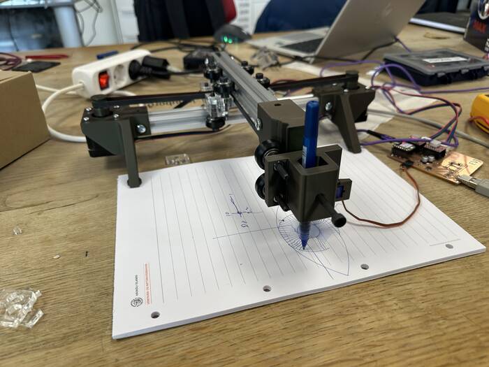
In this week we worked as a group to make Blot machine
Here is link to the machineweek group site
Research
We startet to decided what machine we will do, after we did come to agrement about what machine we wil make we startet by look in to the Blot machine from hackerclub.com, then we try to find out what part we need for that machine, what we can make and what we need to by. We wanted to try to make most of the machine our self and by as little as posible of already ready things. we also try to find out how to make the things, we decided to lasercut some and 3d printed some parts to make our marks on our type of the machine. We are three in our group Albert, Magnús and Evert(me). we then made some plan that Magnus will do the modeling work but me and Albert will try to make our version of the control board with Qc hack on it.
BOM
To make this PCB board i need following material
Qchack
| Material | Size | Pieces |
|---|---|---|
| Resistor | 2.2K | 1 |
| Resistor | 1K | 2 |
| Resistor | 4,7K | 1 |
| Resistor | 10K | 2 |
| Resistor | 47K | 1 |
| Resistor | 1-10µF | 1 |
| USB connector | 1 | |
| Led | Green | 1 |
| Regulator linear Texas instrument | 3,V 100mA | 1 |
| ATtiny 412 | 1 | |
| Pinheader | 1x0.1 P2.54mm | 1-3 |
Blot controle board
| Material | Size | Pieces |
|---|---|---|
| Capasitor | 100nF | 2 |
| Polarised capasitor | 100µF | 2 |
| Connector pinheader socket | 8 footprints | 4 |
| Connector pinheader socket | 7 footprints | 2 |
| S4B-XH-SM4-TB | 2 | |
| Stepper motor driver carrier | A4988 | 2 |
| Con pinheader | 1x03 P2,54mm | 1 |
Making of the PCB board
Here i started by find the drawing of the Qc hack i found that in this page and followed the instruction by Andri
Gerber zip file
PCB trace png
PCB outline png
Kicad zip file
Here is how i started on the PCB board. I started by making new project file in Kicad,

Then i open the schematic drawing and add the components.


Then i go to Easy EDA and make my self account there so i can open the Schematic and PCB file for the Blot machine, it´s possible to use that program online or download it to your computer Download Easy EDA here
When you have download the program then you just install it from download folder in your computer and follow the instruction that will come up on your screen.

Here is how the schematic looks in Easy EDA

After i install Easy EDA i go and download the json files for the controle circut board Here
After that i open the EDA files in Easy EDA so i have reference to make in Kicad for our project.

Then i started to make the control board for the Blot machine in Kicad making the schematic drawing then the PCB routing in this picture we see how the labeling is done in Kicad,

when i was finished the labeling and connecting everything together in the schematic drawing, the drawing was looking like this.

Then i run electric rule checker. it came out with dew warnings but no errors.

The warnings i was getting was about the holes for the USB connector was to close to each other, that was cause the holes wasint cirkle they were more kind of lines that were made off 5 holes drilled to geather on ech side, i fixed that by going into the designe rule checker and made thin minimum hole clerance 0mm bettween the holse, then the warnings did disapared.

When i had the schematic drawing was ready i had to start on the PCB drawing, import the components from the schematic drawing over to the PCB editor, to do that i open the PCB editor then i did uppdate the PCB editor then the components came in to the PCB editor with lines what is supposed to connect to what.
Here you see how to update the PCB editor.

here you see how it is done you need to press update

After i imported components from the schematic to the PCB editor, i routed the board. after that was finished i did run the Design rule checker to see iff any error were made, i got one error pointing on that lines were to close to each oter in one place, i fixed that by moving one of the line a bit further from the other one. then i ran the DRC again. On this picture you can see that there was no errors and how the PCB board was looking after routing.

I got few warnings here but mostly it was silkscreen warnings i did not spend time on fixing that cause this board was not going to pruduction house so it was not relevance in this case.
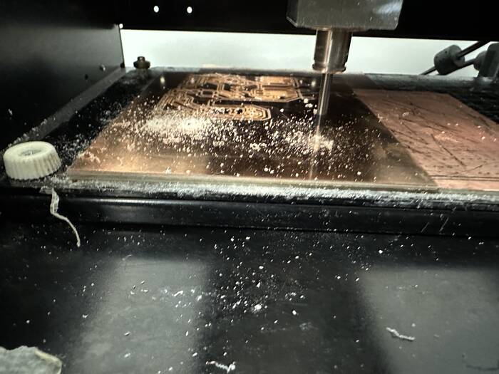
When this part was done i had to make the gerber files to be able to make the board, i was going to use the Roland MDX-20 mill to cut out the board and we use .PNG files to cut after.
Here is how i made the Gerber files.

Then i did plot the files.

Then it was time to make the .PNG files from the gerber files to do that i used the Kerala site gerber2png
 Then the only thing that was left was to mill the board and solder components on it.
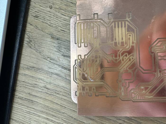
As we can see on this picture i did some mistake when i was milling, me and the Roland mill are not friends, its allways giving me some headach. it did not start at the point i ask it to start, and therefore in the first try tha board was 1,5mm to short like we can see on the pictur below.

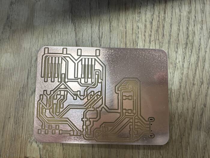
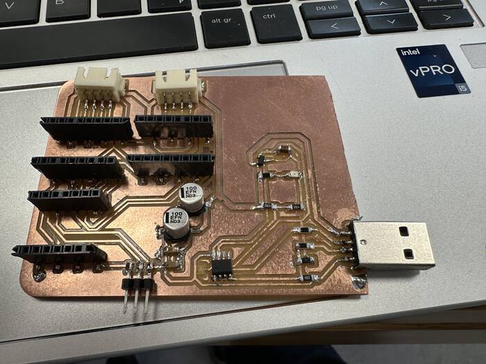
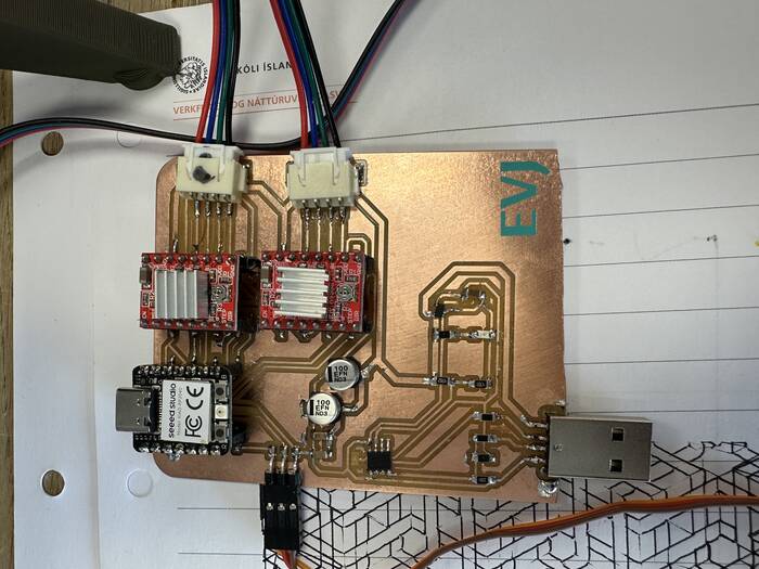
Here we can see final millled board that came out of second attempt.

And here is a little video of the Roland mill working.
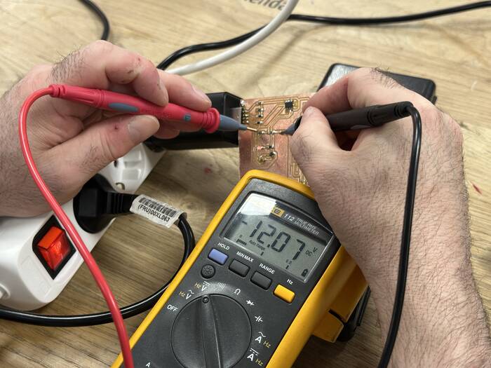
then after it was milled i solder the board first i solder the QChack and got 12V out like i wanted, then i finished to solder the circut.
Here are some pictures from the whole process word not needed:
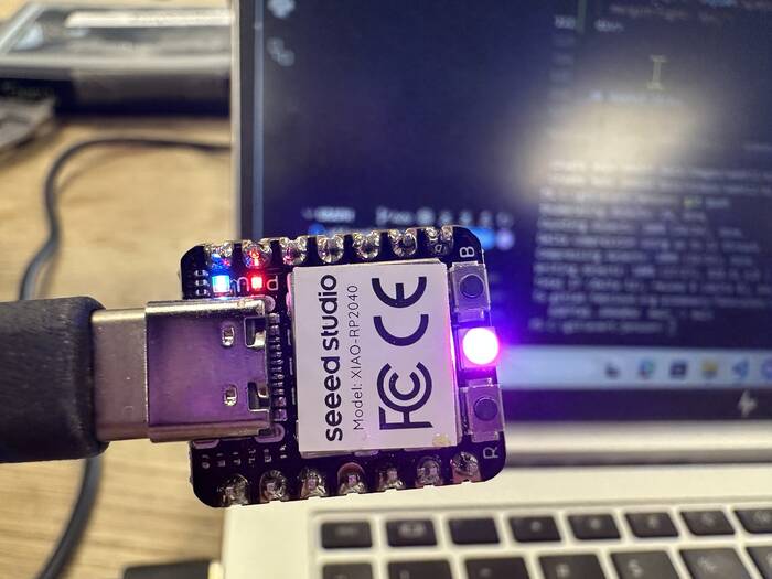
Then i started on programming the RP2040 to do that i started by going to this site Blot Hackerclub to copy the code and then i just paste it inn to arduino IDE
Here is the code: Code .ZIP
#include <Servo.h>

#define SPU 80 // 20 teeth pulley, 16 microstep, 2mm a tooth belt, 16*200 microsteps per turn  == (16*200)/(20*2) == 80
#define PIN_SERVO D6

Servo servo;

typedef uint8_t (*CallbackFunction)(uint8_t*, int, uint8_t*);

struct EventCallback {
  String event;
  CallbackFunction callback;
};


float pos[] = {0, 0};

const int motor1StepPin = D10;
const int motor1DirPin = D9;
const int motor2StepPin = D8;
const int motor2DirPin = D7;

const int enablePin = D1;

void setup() {
  servo.attach(PIN_SERVO);

  Serial.begin(9600);

  // on("light", onLight);
  on("go", go);
  on("servo", moveServo);
  on("motorsOn", motorsOn);
  on("motorsOff", motorsOff);
  on("moveTowardsOrigin", moveTowardsOrigin);
  on("setOrigin", setOrigin);

  pinMode(motor1StepPin, OUTPUT);
  pinMode(motor1DirPin, OUTPUT);
  pinMode(motor2StepPin, OUTPUT);
  pinMode(motor2DirPin, OUTPUT);

  pinMode(enablePin, OUTPUT); // enable pin

  pinMode(PIN_LED, OUTPUT);

  startupIndicator(); // once startup is finished, indicate to user
}

void loop() {
  readSerial();
}

void startupIndicator() {
  // flash LED to indicate board is initialized
  for (int i = 0; i < 3; i++) {
    digitalWrite(PIN_LED, 0);
    delay(200);
    digitalWrite(PIN_LED, 1);
    delay(200);
  }
}

uint8_t onLight(uint8_t* payload, int length, uint8_t* reply) {
  uint8_t value = payload[0];

  // Serial.println("light it up");

  digitalWrite(PIN_LED, value);

  return 0;
}

uint8_t motorsOn(uint8_t* payload, int length, uint8_t* reply) {
  digitalWrite(enablePin, 0);
  return 0;
}

uint8_t motorsOff(uint8_t* payload, int length, uint8_t* reply) {
  digitalWrite(enablePin, 1);
  return 0;
}

uint8_t moveTowardsOrigin(uint8_t* payload, int length, uint8_t* reply) {
  float x = pos[0];
  float y = pos[1];

  // this ternary may not be neccesary
  goTo(
    x + ( x < 0 ? 10 : -10),
    y + ( y < 0 ? 10 : -10)
  );

  return 0;
}

uint8_t setOrigin(uint8_t* payload, int length, uint8_t* reply) {
  pos[0] = 0;
  pos[1] = 0;

  return 0;
}


/* ------------------------------------------------------------ */

int bufferIndex = 0;
uint8_t msgBuffer[100];

void readSerial() {
  while (Serial.available() > 0) {
    uint8_t incoming = Serial.read();

    msgBuffer[bufferIndex] = incoming;

    if (incoming != 0) {
      bufferIndex++;
      continue; // Proceed to the next byte if current byte is not null
    }

    // Serial.print("RECEIVED: ");
    // for (int i = 0; i < bufferIndex; i++) {
    //   Serial.print(msgBuffer[i]);
    //   Serial.print(", ");
    // }
    // Serial.println("DONE");

    // Now we have a full message, perform COBS decoding
    uint8_t decoded[bufferIndex];
    cobs_decode(decoded, msgBuffer, bufferIndex);

    // Serial.print("DECODED: ");
    // for (int i = 0; i < bufferIndex; i++) {
    //   Serial.print(decoded[i]);
    //   Serial.print(", ");
    // }
    // Serial.println("DONE");

    // Parse the decoded message
    int i = 0;

    uint8_t msgLength = decoded[i];
    // Serial.print("MSG-LENGTH: ");
    // Serial.println(msgLength);

    uint8_t msgArr[msgLength];
    i++;
    while (i < 1 + msgLength) {
      msgArr[i-1] = decoded[i];
      i++;
    }

    // Serial.print("MSGARR: ");
    // for (int i = 0; i < msgLength; i++) {
    //   Serial.print(msgArr[i]);
    //   Serial.print(", ");
    // }
    // Serial.println("MSGARR-END");

    uint8_t payloadLength = decoded[i];
    uint8_t payload[payloadLength];
    i++;
    while (i < 1 + msgLength + 1 + payloadLength) {
      payload[i-1-msgLength-1] = decoded[i];
      i++;
    }

    uint8_t msgCount = decoded[i];

    // String msg = String((char*)msgArr);
    String msg = byteArrayToString(msgArr, msgLength);

    // Serial.println(msg);

    // printArray("PAYLOAD", payload, payloadLength);

    // Serial.print("MSGCOUNT: ");
    // Serial.println(msgCount);

    bool triggered = triggerEvent(msg, payload, payloadLength, msgCount);

    bufferIndex = 0; // Reset the buffer for the next message
  }
}

/* ------------------------------------------------------------ */


const int MAX_EVENTS = 255; // Maximum number of events to store, adjust as needed
EventCallback eventCallbacks[MAX_EVENTS];
int eventCount = 0;

const int REPLY_PAYLOAD_LENGTH = 255;
uint8_t reply[REPLY_PAYLOAD_LENGTH];

void on(String event, CallbackFunction callback) {
  if (eventCount < MAX_EVENTS) {
    eventCallbacks[eventCount].event = event;
    eventCallbacks[eventCount].callback = callback;
    eventCount = (eventCount + 1) % MAX_EVENTS;
  } else {
    // Serial.println("Max number of events reached. Wrapping events.");
  }
}

bool triggerEvent(String event, uint8_t* payload, int payloadLength, uint8_t msgCount) {
  for (int i = 0; i < eventCount; i++) {
    if (eventCallbacks[i].event == event) {
      // want to pass payload and payloadLength, need to get response payload
      uint8_t reply_length = eventCallbacks[i].callback(payload, payloadLength, reply);

      sendAck(msgCount, reply, reply_length);
      return true;
    }
  }

  // Serial.println(" No event registered.");
  return false;
}

const int arrayLength = 7; // + length;
uint8_t byteArray[arrayLength];

void sendAck(uint8_t msgCount, uint8_t* reply, uint8_t length) {
  // Serial.println("SEND ACK");

  // int arrayLength = 7; // + length;
  // static uint8_t byteArray[arrayLength];

  byteArray[0] = 0x03;
  byteArray[1] = 0x61;
  byteArray[2] = 0x63;
  byteArray[3] = 0x6B;
  byteArray[4] = 0x00;
  byteArray[5] = msgCount;
  byteArray[6] = 0x0A;

  // byteArray[4] = length;
  // for (int i = 0; i < length; i++) {
  //   byteArray[i+5] = reply[i];
  // }
  // byteArray[5+length] = msgCount;
  // byteArray[6+length] = 0x0A;

  // Serial.println(msgCount);
  // printArray("ACK", byteArray, 5+length);

  Serial.write(byteArray, arrayLength);

  // uint8_t byteArrayEncoded[arrayLength + 2]; // +2 for possible COBS overhead
  // cobs_encode(byteArrayEncoded, byteArray, arrayLength);
  // Serial.write(byteArrayEncoded, arrayLength + 2);

  // printArray("ENCODED-ACK", byteArray, 5+length);

}

/* ------------------------------------------------------------ */

void cobs_encode(uint8_t *dst, const uint8_t *src, size_t len) {
    size_t read_index = 0;
    size_t write_index = 1;
    size_t code_index = 0;
    uint8_t code = 1;

    while (read_index < len) {
        if (src[read_index] == 0) {
            dst[code_index] = code;
            code = 1;
            code_index = write_index++;
            read_index++;
        } else {
            dst[write_index++] = src[read_index++];
            code++;
            if (code == 0xFF) {
                dst[code_index] = code;
                code = 1;
                code_index = write_index++;
            }
        }
    }

    dst[code_index] = code;

    // Add trailing zero
    if (write_index < len + 2) {
        dst[write_index] = 0;
    }
}

void cobs_decode(uint8_t *dst, const uint8_t *src, size_t len) {
    size_t i, j, dst_i = 0;
    for (i = 0; i < len;) {
        uint8_t code = src[i++];
        for (j = 1; j < code && i < len; j++) {
            dst[dst_i++] = src[i++];
        }
        if (code < 0xFF && dst_i < len) {
            dst[dst_i++] = 0;
        }
    }
}

/* ------------------------------------------------------------ */

// TODO: THINK THIS IS BUGGY
void cobs_print(const String& message) {
  // Convert the message to a byte array
  int length = message.length();
  uint8_t byteArray[length + 1]; // +1 for the null terminator
  message.getBytes(byteArray, length + 1);

  // Prepare the buffer for the encoded message
  uint8_t encoded[length + 2]; // +2 for possible COBS overhead

  // Perform COBS encoding
  cobs_encode(encoded, byteArray, length + 1);

  // Send the encoded message
  Serial.write(encoded, length + 2); // Write the encoded bytes
}

/* ------------------------------------------------------------ */

float read_float(uint8_t* buffer, int index) {
  uint8_t byte0 = buffer[index];
  uint8_t byte1 = buffer[index+1];
  uint8_t byte2 = buffer[index+2];
  uint8_t byte3 = buffer[index+3];

  uint8_t byteArray[] = {byte0, byte1, byte2, byte3};
  float floatValue;
  memcpy(&floatValue, &byteArray, sizeof(floatValue));

  return floatValue;
}

int read_int(uint8_t* buffer, int index) {
  uint8_t byte0 = buffer[index];
  uint8_t byte1 = buffer[index+1];
  uint8_t byte2 = buffer[index+2];
  uint8_t byte3 = buffer[index+3];

  uint8_t byteArray[] = {byte0, byte1, byte2, byte3};
  int value;
  memcpy(&value, &byteArray, sizeof(value));

  return value;
}

String byteArrayToString(byte arr[], int length) {
  String result = "";

  for (int i = 0; i < length; i++) {
    result += (char)arr[i]; // Convert each byte to a character and append it to the string
  }

  return result;
}

/* ------------------------------------------------------------------------ */

#define EPSILON 0.01

void goTo(float x, float y) {

  // Serial.println("START GOTO");

  // Set your target distances for each motor (in steps)
  float motor1Target = (x + y) - pos[0];
  float motor2Target = (y - x) - pos[1];

  // Set motor direction based on target values
  digitalWrite(motor1DirPin, motor1Target >= 0 ? HIGH : LOW);
  digitalWrite(motor2DirPin, motor2Target >= 0 ? HIGH : LOW);

  // Calculate the relative speeds and maximum duration for both motors
  float maxSteps = max(abs(motor1Target), abs(motor2Target));
  float motor1Speed = abs(motor1Target) / maxSteps;
  float motor2Speed = abs(motor2Target) / maxSteps;

  unsigned long stepDuration = 500; // The time it takes to perform one step in microseconds
  unsigned long motor1StepInterval = stepDuration / motor1Speed;
  unsigned long motor2StepInterval = stepDuration / motor2Speed;

  // Initialize variables for step timing
  unsigned long motor1PrevStepTime = 0;
  unsigned long motor2PrevStepTime = 0;
  float motor1Step = 0;
  float motor2Step = 0;

  // Loop until both motors reach their target steps
  while (abs(motor1Target - motor1Step) > EPSILON || abs(motor2Target - motor2Step) > EPSILON) {


    unsigned long currentTime = micros();

    // Motor 1
    if (abs(motor1Target - motor1Step) > EPSILON && ((currentTime - motor1PrevStepTime) >= motor1StepInterval)) {
      digitalWrite(motor1StepPin, HIGH);
      delayMicroseconds(1);
      digitalWrite(motor1StepPin, LOW);
      delayMicroseconds(1);

      motor1Step += (motor1Target >= 0 ? 1.0 : -1.0)/SPU;
      motor1PrevStepTime = currentTime;
    }

    // Motor 2
    if (abs(motor2Target - motor2Step) > EPSILON && ((currentTime - motor2PrevStepTime) >= motor2StepInterval)) {
      digitalWrite(motor2StepPin, HIGH);
      delayMicroseconds(1);
      digitalWrite(motor2StepPin, LOW);
      delayMicroseconds(1);

      motor2Step += (motor2Target >= 0 ? 1.0 : -1.0)/SPU;
      motor2PrevStepTime = currentTime;
    }
  }

  // Serial.println("END GOTO");

  pos[0] += motor1Step;
  pos[1] += motor2Step;
}

uint8_t go(uint8_t* payload, int length, uint8_t* reply) {
  float x = read_float(payload, 0);
  float y = read_float(payload, 4);

  goTo(x, y);

  return 0;
}

uint8_t moveServo(uint8_t* payload, int length, uint8_t* reply) {
  int angle = read_int(payload, 0);

  servo.writeMicroseconds(angle);

  return 0;
}

/* ------ */

void printArray(String label, uint8_t* arr, int arrSize) {
  Serial.print(label);
  Serial.print("-BEGIN: ");
  for (int i = 0; i < arrSize; i++) {
    Serial.print(arr[i]);
    Serial.print(", ");
  }
  Serial.print(label);
  Serial.println("-END");
}
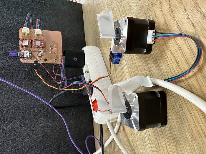
And after programming the RP2040 i connected the board to three motors and went into blot hackclub editor and run a test program. and for my big surprice everything works like it supposed.
programing the plotter
After the machine was ready we tested the machin by runing a default code from the gallery at hackclub we also made the machin draw a picture of Neil, Albert made the program for that and i refer to his documentation about how that was done
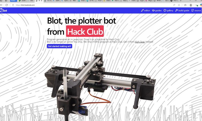
On these picture we can see the main page to the bot hacker club we can use two ways to go in to the editor either by clicking the editor sign,

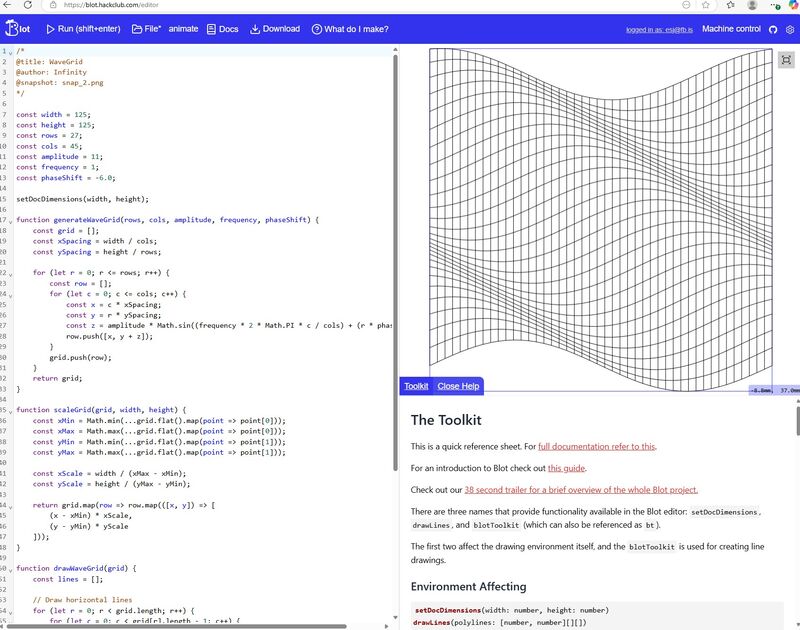
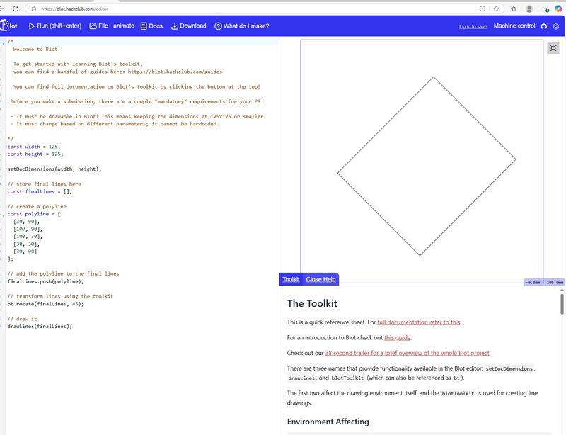
or like i did i went trough the gallery button. and in the gallery part of the site we scrolled trough that site until we found the pattern we wanted to test
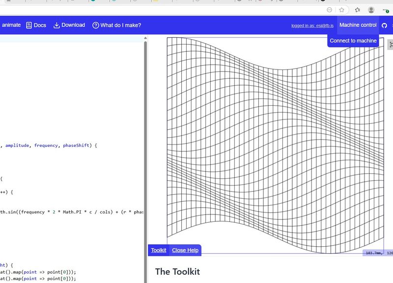
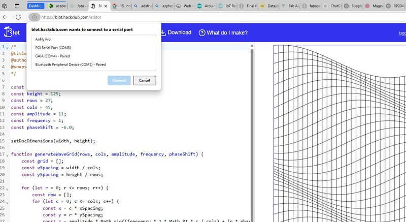
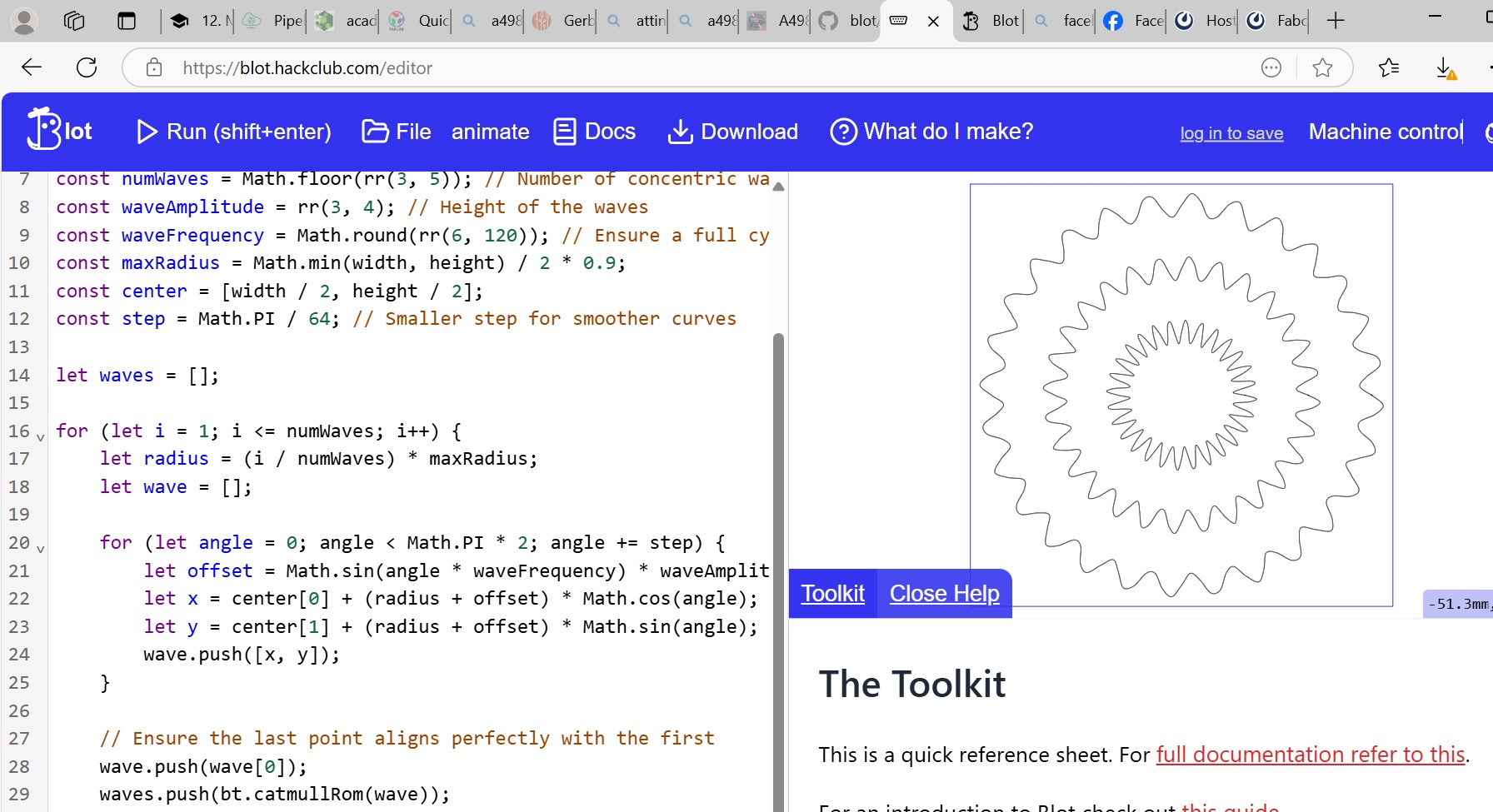
Then we were in this window and it was tome to connect the machine to the computer and the program we used USB to connect the machine to the computer and in the program we need to press in the opper right corner on the button machine controle, then the second window opens and you need to chiche the computer and com port in your case we had RP2040 on the list and choice that one(not seen on the screen cause the RP2040 wasent connectet to the computer when this picture was taken)

Here on this picture we she the code on the left side and the pattern to draw on the right side. We also se the machine controle board that we use to run the machine, first thing we need to do before running the machine is setting origin, that is done by pressing move towards origin then the machine moves shortly in to direction tha point to the origin then we move the machine by hands to that corner then we press set origin button and then the machine is ready to run