8. Electronics Production
This week assignment
group assignment: - characterize the design rules for your in-house PCB production process - submit a PCB design to a board house individual assignment: - make and test a microcontroller development board that you designed - extra credit: make it with another process
Progress
- Grupp assignment
- [ ]- Characterize the design rules for your in-house PCB production process.
- Dubmit a PCB designe to a board house
- Document
- Induvidual assignment
- Make and test a microcontroller development board that you designed
- Document that process
- extra credit: make it with another process
Research
This week assignment is about to mill and solder that board and get ir to work as it was designed. I have experience in using Roland MDX-20 mill and made few PCB boards last year or so, i didint really do much research this week i just went straight trough and produced the board i made in week 06. However i did also investigate other mills and did order Lunyee 3018 pro mill, it arrived late this week and i was not able to get it up and running to test it in this week there for that machine was not use to do this assingment i also study control software for the lunyee mill called candle it seems to me it´s easy going software and i am looking much forward to test this machine as soon as the spare part i need arrives. To get this week assignment done i also need to program hte RP2040 that i used most reserch for that was done in week 06.
The PCB borad Production
In week 06 i designed a PCB board in Kicad, this week i am going to produce the board and get it working.
I did designe a simple board using few thing. This board is supposed to work like this:
- On start, it will power up and nothing more will happen.
- Press buttomn once, led 1 will turn on.
- Press button second time, led 1 will stay on and led 2 will turn on.
- Press button third time, led 1 and 2 wil start blinking.’
- Press button fourth time, both led wil turn off.
Then we go to the producion of the board, after design it in Kicad i ended op with gerber files , the program we use on the Roland MDX-20 mill at fablab reykjavæik uses .png to mill after so first thing i need to do is change gerberfiles in to .png. How do i do that wekk there are several ways to do that, one is to use inkscape making vectors fro .svg files thats not realy good or effective way cause we have much better tool do do this work, our friends in Kerala have made this wonderfull website called gerber2png were you simply drag the gerberfiles in that page and the page will turn them into .png files for you.

Then after that you will just download the ,png and safe it on your computer on a location of your choice.
then you are ready to go to the milling process.
First thing that you have to do is making sure the mill and the server is on, then you will connect your computer to the server through server software that is called Fabmodules. Fab Modules is a browser-based CAM system, which allows to generate toolpaths for and control lasercutters, CNC-mills.
The first thing i had to do was staring up the server to do that i use CLI interface on the raspberrypi computer that is connected to the mill with this comand
npm start
Then you connect your computer to the same Wifi as the server is on and connect to the server by the io address that the server is using in this case 10.50.0.29:12345
then you should get this window up:

Then you are connected and ready to start setting up the mill for the work you want it to do.
Main settings:
- Speed:
- Spindle Speed: 10,000 RPM
-
Feed Rate:
- X/Y Feed Rate: 10 mm/s
- Z Feed Rate: 2 mm/s
-
Cutting Depth:
-
Trace Cutting Depth: 0.1 mm
- Outline Cutting Depth: 0.8 mm

Then you choice import format > images png then you brows your computer to find the png file of your trace, we allways start on the trace and end on cuting

Next is to choice output format > Roland mill

then you go to trace > trace 1/64

then you sett parameters like you can see on this picture below.
Then when all parameters and ip adress have been sett you press calculate button and if everything look good you press send and the gcode will be send to the machine and the machine will mill the trace route when finished milling the trace you do the same procedure again but in stead of choiching trace 1/64 you choice outline 1/32

Then after i cut out the PCB board i did sand it down with a wet spoonse to take away sharp edge from the bord so the components have better seat on the board then the board was ready for soldering, that is always a challenge for me to solder so after trying to solder some resistors and mesh it up i decided to try solder paste i add som solderpaste on the footprints put the leds on the foot prints then i did use the solderstation preheat board function to preheat the bord then i use heatgun and heat up the area where i hade the solder paste and what a magjick it worked so well that i think i will bee using that more than my new solder iron


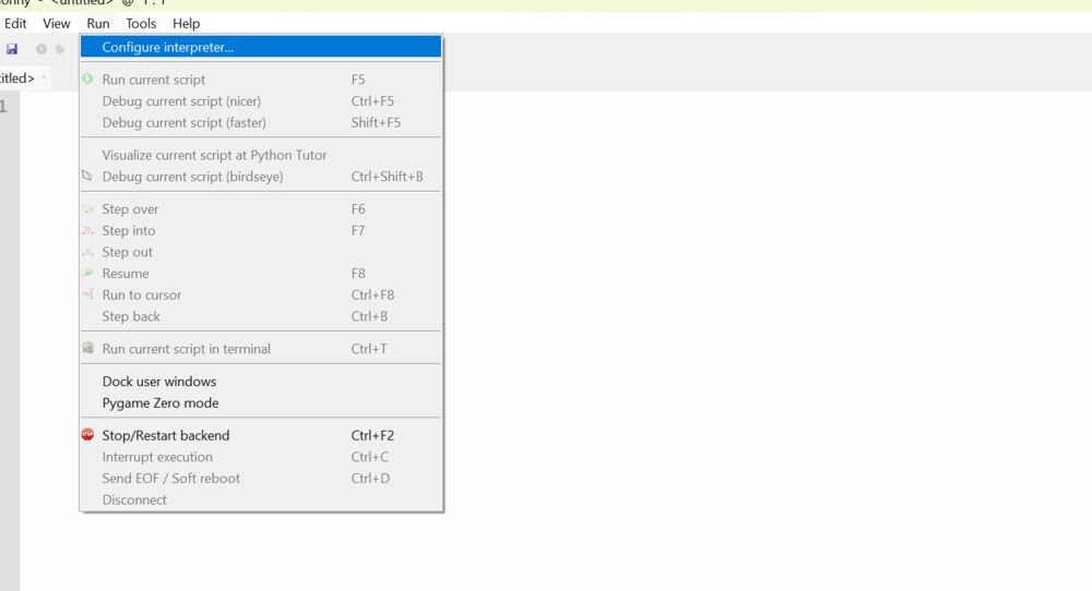
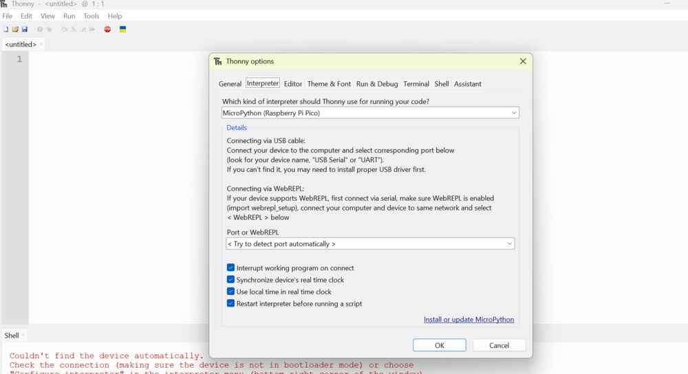
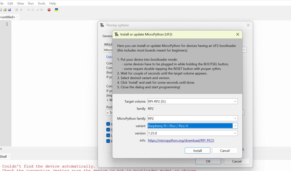
In the end i had to program the RP-2040 so the board will be working as expected i did use python and thonny to do that. Thonny Thonny is an Integrated Development Environment (IDE) designed for beginners learning Python programming. It includes Python built-in, so there’s no need for separate installation. I startet to download Thonny and install it. Then i open Thonny and first i did open new project then i started by set up the RP-2040 in Thonny how i did that you will see in the following pictures
pictures of thonny


The code i used was this code i got with good help from Copilot, i told Copilot how i wanted the board to work that is this describsion:
- Board powerd up nothing happen.
- Button press once led one turns on.
- Button pressed twice led one and tvo turns On
- Button pressed third time bothe leds start blinking
- Button pressed fourth time both leds turns off.
- led one is pin 2
- led tvo is pin 3
- button is pin 4
Then copilot gave me this code.
    from machine import Pin
import time

# Define pins
led1 = Pin(2, Pin.OUT)
led2 = Pin(3, Pin.OUT)
button = Pin(4, Pin.IN, Pin.PULL_DOWN)

# Initial state
state = 0

def update_leds(state):
    if state == 0:
        led1.value(0)
        led2.value(0)
    elif state == 1:
        led1.value(1)
        led2.value(0)
    elif state == 2:
        led1.value(1)
        led2.value(1)
    elif state == 3:
        for _ in range(5):  # Blink 5 times
            led1.value(1)
            led2.value(1)
            time.sleep(0.5)
            led1.value(0)
            led2.value(0)
            time.sleep(0.5)

while True:
    if button.value() == 1:
        state = (state + 1) % 4
        update_leds(state)
        time.sleep(0.3)  # Debounce delay
BUTT IT DIDINT WORK AT ALL NOTHING HAPPEND WITH THIS CODE
So i try to find out why it did not work, im not good in programming so i turn into the Fablab cicle in Iceland for help. i got some tips from Þórarinn in Fablab Ísafjörður og Andri my instructor, after i did go over there points. i did end up whit this code. remarks in the code what was changes from the orginal Here is the final code i used:
from machine import Pin
import time

# Define pins
led1 = Pin(27, Pin.OUT)
led2 = Pin(28, Pin.OUT)
button = Pin(29, Pin.IN, Pin.PULL_UP) # change to pull up from PULL_DOWN

# Initial state
state = 0

def update_leds(state):
    if state == 0:
        led1.value(0)
        led2.value(0)
        print("state0")
    elif state == 1:
        led1.value(1)
        led2.value(0)
        print("state 1")
    elif state == 2:
        led1.value(1)
        led2.value(1)
        print("state 2")
    elif state == 3:
        for _ in range(5):  # Blink 5 times
            led1.value(1)
            led2.value(1)
            time.sleep(0.5)
            led1.value(0)
            led2.value(0)
            time.sleep(0.5)
            print("state 3")

while True:
    if button.value() == 0: #change button state í 0
        state = (state + 1) % 4
        update_leds(state)
        time.sleep(0.3)  # Debounce delay
        print("wowo") #adding some print commands here end there
Here is litle something final video of the final product and how it´s works