6. Electronics Design
Task: Electronics Design
Group assignment:
- Use the test equipment in your lab to observe the operation of a microcontroller circuit board (as a minimum, you should demonstrate the use of a multimeter and oscilloscope)
- Document your work on the group work page and reflect what you learned on your individual page
Individual assignment:
- Use an EDA tool to design a development board that uses parts from the inventory to interact and communicate with an embedded microcontroller
Research
This week we have gruppe assignment to test out multimetar and oscillascope to observe some microcontroler at work, well i have used multimete in my work for 3 years so i dont need to learn on the multimeter, Oscillascope i havent use to much but im familiar with it so i exðect that i will just document how to use this tools.
Individual task is use EDa tool to designe a developement bord, i have kicad installedd in my computer and have used it little bit, i have watch gruppe of videos about kicad 7 i had kicad 8 in my computer, when i start google and browsing the internet i saw that it’s already been relesed Kicad 9 so i downloaded it. Then i didt google little bid about fusion and the Eagle EDA inside fusion.
Gruppe assignment
In this group assignment i did the measure of capasitor and voltages and then we were exploring ocilascope. I am an electrician so i am used to use multimeter and therefor dod not learn anything new in how to use multimeter. I am also familiar with the scope from before but it was good to refresh my knowlges on the scope.
develope circut board in Kicad
In the individual project this week i am suppose to design electircal circut using EDA tool, i am going to use Kicad for this assignment.
First thing i did was update kicad in my computer, to do that i went to Kicad download site and downloaded Kicad 9 for windows.
Setting up fab kicad library
Then i had to sett up the Fablab library, thats how i did that.
1. downloaded the library from this link Fablab kicad library.
2. went to download folder, found the zip folder i already downloaded.
3. right click on that folder with the mouse then choice “extract all” from the drop down meny, choice the folder that you want to kepp the library in, that can be something like ../document/kicad/library.
4. Open Kicad.
5. Go to “Preferences / Manage Symbol Libraries” and add fab.kicad_sym as symbol library.
6. Go to “Preferences / Manage Footprint Libraries” and add fab.pretty as footprint library.
7. Go to “Preferences / Configure Paths” and add new environment variable “FAB” that points to location of the fab library on your drive, e.g. ~/kicad/libraries/fab. This is needed for the 3D models to load correctly.


Next is start designing
To designe this bord i am going to use Kicad 9,
i am going to make little circut that has:
2 1kohm resistors
2 LED diodes (green)
1 Button
RP 2040 Xiao SEEED STUDIO microcontroler
This circut is going to work like this, when you power the circut nothing happens, then when you press the button once ony one diode will ligt up, when you press the button second time both diode wil be lighting up, when you press the button third time both diode will start blinking. when you press the button fourth time bothe diode wil shut down. then new secuence will start.
Connecting Diagram for that circut
| Component | XIAO RP2040 Pin | Other Connection |
|---|---|---|
| LED 1 Anode | D2 | |
| LED 1 Cathode | Resistor 1 | |
| Resistor 1 | GND | |
| LED 2 Anode | D3 | |
| LED 2 Cathode | Resistor 2 | |
| Resistor 2 | GND | |
| Button | D4 | GND |
| VCC | 3.3V | |
| GND | GND |
Posible python code
    from machine import Pin
import time

# Define pins
led1 = Pin(2, Pin.OUT)
led2 = Pin(3, Pin.OUT)
button = Pin(4, Pin.IN, Pin.PULL_DOWN)

# Initial state
state = 0

def update_leds(state):
    if state == 0:
        led1.value(0)
        led2.value(0)
    elif state == 1:
        led1.value(1)
        led2.value(0)
    elif state == 2:
        led1.value(1)
        led2.value(1)
    elif state == 3:
        for _ in range(5):  # Blink 5 times
            led1.value(1)
            led2.value(1)
            time.sleep(0.5)
            led1.value(0)
            led2.value(0)
            time.sleep(0.5)

while True:
    if button.value() == 1:
        state = (state + 1) % 4
        update_leds(state)
        time.sleep(0.3)  # Debounce delay
Posible C++ Code
         #include <Arduino.h>

// Define pins
const int led1Pin = 2;
const int led2Pin = 3;
const int buttonPin = 4;

// Initial state
int state = 0;
bool buttonPressed = false;

void setup() {
  // Initialize pins
  pinMode(led1Pin, OUTPUT);
  pinMode(led2Pin, OUTPUT);
  pinMode(buttonPin, INPUT_PULLDOWN);
}

void loop() {
  // Check if the button is pressed
  if (digitalRead(buttonPin) == HIGH && !buttonPressed) {
    buttonPressed = true;
    state = (state + 1) % 4; // Cycle through states
    updateLEDs(state);
    delay(300); // Debounce delay
  } else if (digitalRead(buttonPin) == LOW) {
    buttonPressed = false;
  }
}

void updateLEDs(int state) {
  switch (state) {
    case 0:
      digitalWrite(led1Pin, LOW);
      digitalWrite(led2Pin, LOW);
      break;
    case 1:
      digitalWrite(led1Pin, HIGH);
      digitalWrite(led2Pin, LOW);
      break;
    case 2:
      digitalWrite(led1Pin, HIGH);
      digitalWrite(led2Pin, HIGH);
      break;
    case 3:
      for (int i = 0; i < 5; i++) { // Blink 5 times
        digitalWrite(led1Pin, HIGH);
        digitalWrite(led2Pin, HIGH);
        delay(500);
        digitalWrite(led1Pin, LOW);
        digitalWrite(led2Pin, LOW);
        delay(500);
      }
      break;
  }
}
How to make circut in Kicad
Like i said before then i had Kicad already installed in my computer so im not going to cover that part but you can find it here
Now we go to the documentasion of making the schematic design of the board im going to make as this week assignment. I startet by opening kicad in my computer then i go to the left side menu and click on new project.

Thats how it looks when new project has been open.

Then i open schematic settings to go over the settings, here i used the default settings so i did not change any thing at that time.

Then i did set the electrical rules for the ERC(Electrical Rules Checker) I used default here.

Then i startet by find the symbols for resistor, led, tactical button and Xiao seeed studio RP2040. and drawing

Then i connected things with labels and by puting power flags

Then i was finished and it look like this.

Then when that was finished i did run the electrical rules checker to ensure all things are connected and no failure in the circut, ERC will follow the rules that was set in the schematic setting earlier. i got 3 error in the check lines missing beetween symbols i fixed that then i got this from the ERC

Then i did open PCB editor direct from schematic to start importing the project and starting to make the PCB board it self, addjust the component and make traces and outline cuting line.
 Then i was finished and it look like this.

PCB board
At this point its time to make the PCB board, connect it and 3d model.
We already open the PCB edidtor then we go to Design rules tab nd set the designe rules, design rules are the rules that we have to have about margin beetween lines and other things on the PCB board, here we also set the size on the coppar traces. it is recomendeet to have power traces bigger than signal tracess both so it easier to see what is power/ground and the signal line. Also to make sure power lines ar big enough.

After that i make the shape of the circut i go for rectangular and have it around 40mm x 50mm

Then i have to import components from schematic drawing that is done by update PCB board

Then i have to plase all the components on the plate inside the area i made before(the form i made)

Then its time to connect all components to geather following the line that is beetween them

Design rule checker showed no problem.

Then in the end we do run the design rules and see if everything is good i had no problem here, and then we can see how it look in 3D by looking at the 3D model.

Here is the Orginal Kicad file
Here is the kicad Zip file
That was all for the week06 induvidual assignment, i am how ever considering to add to led’s to the board one that is direct connected to the 5V out put, led that wil light up when the board is powerd, it is led on the RP2040 that lights up when powerd but i have been advised it can be good to have one on the board it self in case the inbuildt one fails, then im thinking to connect other led beetween pin 10 and ground for test purpose so it easy to set code in to the board that set pin to high and then will turn on that led, all led have to have resistor connected to it so this will call for two resistor in addition to those we had before and little more space on the board. it’s relativ easy to add on the board i just have to add it on the schematic drawing, update PCB and place it on the board and draw the lines, most likely i have to enlarge the board and/or re arange the other components on the board. i think it’s very likely if posible to use the same board in the week we need to produce our own board. If i do this i also have to alter the code then i will also add som features that wil print to the screen whats going on on the board like print “button press once led 1 turns on” for example.
Result and final code
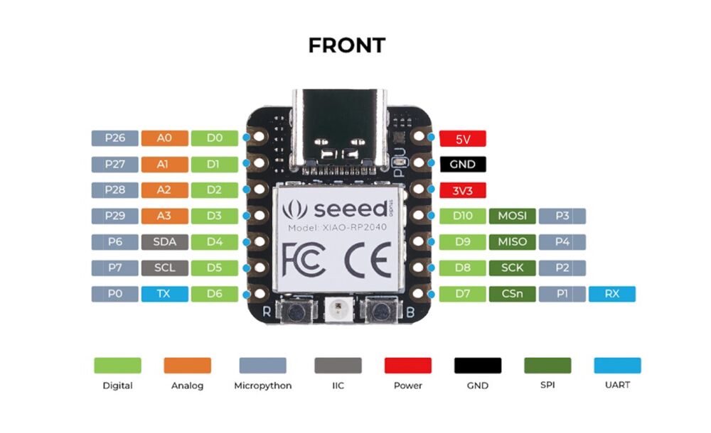
When i had already produced my board i try to program it with the code i provided earlier in this documentaion, but that did not work i tried bot arduino an Thonny. in the end i dound out i needed to cangh the code little bit, it turned out i also use wrong pin number.


Here we can see to different picture of the pin out on Rp2040 i did try to use the pin out number from the picture to the right first but that did not work then i was pointet towards the pin out that is seen on thepicture to the left by my instructor Andri and i try to change the pinout numbers in the code and then it worked.
Here is video that shows how this project works.
here is the final mycropython code used. I got little help with the code from Þórarinn in Fab ísafjörður
from machine import Pin
import time

# Define pins
led1 = Pin(27, Pin.OUT)
led2 = Pin(28, Pin.OUT)
button = Pin(29, Pin.IN, Pin.PULL_UP) # change to pull up from PULL_DOWN

# Initial state
state = 0

def update_leds(state):
    if state == 0:
        led1.value(0)
        led2.value(0)
        print("state0")
    elif state == 1:
        led1.value(1)
        led2.value(0)
        print("state 1")
    elif state == 2:
        led1.value(1)
        led2.value(1)
        print("state 2")
    elif state == 3:
        for _ in range(5):  # Blink 5 times
            led1.value(1)
            led2.value(1)
            time.sleep(0.5)
            led1.value(0)
            led2.value(0)
            time.sleep(0.5)
            print("state 3")

while True:
    if button.value() == 0: #change button state í 0
        state = (state + 1) % 4
        update_leds(state)
        time.sleep(0.3)  # Debounce delay
        print("wowo") #adding some print commands here end there