4. Embedded Programming
Assignment
-
Group assignment:
-
Demonstrate and compare the toolchains and development workflows for available embedded architectures
- Document your work to the group work page and reflect on your individual page what you learned
-
Individual assignment:
-
Browse through the datasheet for your microcontroller
- Write a program for a microcontroller, and simulate its operation, to interact (with local input &/or output devices) and communicate (with remote wired or wireless connection)
Research
In this week assignment i started the research by looking at the ATTiny 412 and how to procram and simulate little circuit with it. I did research on how to program ATtiny with arduino IDE using C++ language. I also did try to find out what kind of assignment you can use ATtiny for.
Then i studydatasheet for XIAO RP2040 trying to figure out what is it strength and weekness. I will document the outcome further on this site.
Studying datasheet for RP-2040
I found the datasheet here, then the seeed studio page leed me to this wiki studio page that wiki page is very good to learn about there products.
I made an comparision table for RP2040 and ESP32-C3 from informasion i fond on the Seeed studio wiki page
| Item | Seeed studio XIAO-RP2040 | Seeed studio XIAO ESP32C3 |
|---|---|---|
| processor | RP2040 Daul-core M0+@133Mhz | ESP32-C3 32-bit RISC-V@160Mhz |
| Wireless Connectivity | N/A | WiFi and Bluetooth 5(le) |
| Memory | 264KB SRAM, 2MB onboard Flash | 400KB SRAM, 4MB onboard Flash |
| Built-in Sensors | N/A | N/A |
| Interfaces | 12C/UART/SPI | 12C/UART/SPI/125 |
| PWM/Analog Pins | 11/4 | 11/4 |
| Onboard Buttons | Reset/Boot Button | Reset/Boot Button |
| Onboard LEDs | Full-color RGB/ 3-in-one | Charge LED |
| Battery Charge Chip | N/A | Built-in |
| Programing Languages | Arduino/ MicroPython/ CircuitPython | Arduino |
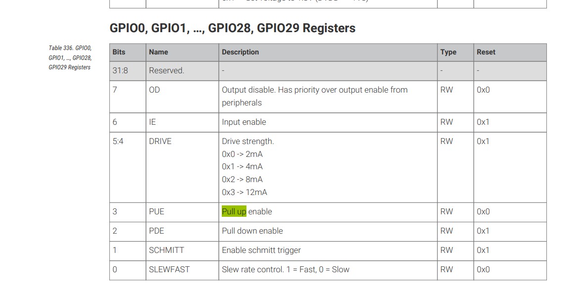

On these pictures we can see that the pull up and pull down function is enable on the GPIO pins.
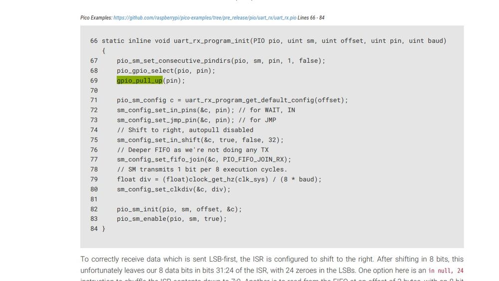
Then we see some example of how we can enable the pins by code.
Third picture show us the current that can be send on the pins, explaning the effec between current and voltage and load.
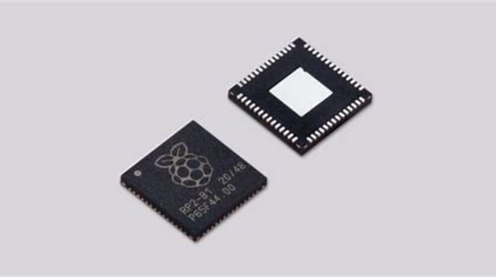
 This picture show what RP2040 standsfor and has little summari over the chip.
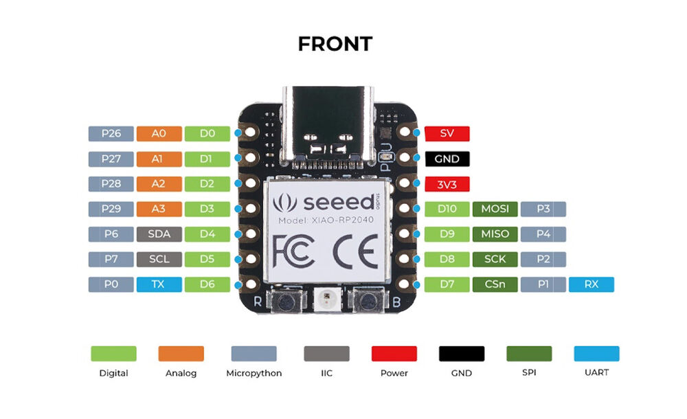
 This is the pin out picture showing the GPIO pins and number on the actual RP2040 chip, the XIAO RP2040 has nott all that pins and may not have the same number.

On this picture we see all info about the memory to the chip.
The main differences between ROM (Read-Only Memory) and SRAM (Static Random-Access Memory) are based on their functionality, volatility, and usage: - Functionality: ROM is non-volatile memory used to store firmware or software that is rarely changed. It retains its data even when the power is turned off. - Functionality: SRAM is volatile memory used for temporary data storage that requires fast access. It loses its data when the power is turned off.
 Here we can see various information on the power supply min max voltage and what is typical considering what type of power supply we use.
 Here we see the pin types, and what direction they go input/output or both and som description on what they are for and how they work.
 And then the pin list with GPIO number , type, power domein on thepin reset state and description.
Programming ATtiny412 with Arduino IDE
What You Need:
- ATtiny412 microcontroller
- Arduino IDE (latest version)
- Serial UDPI cable
- Serial UDPI 3 pin Addapter
Step 1: Set Up Support for ATtiny 1-Series in Arduino IDE
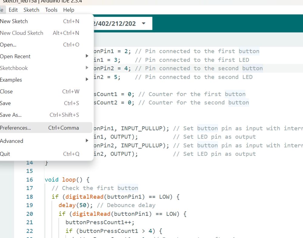
- Open the Arduino IDE.
- Go to File > Preferences.
-
In the “Additional Boards Manager URLs” field, add the following URL: Json file for arduino


-
Click OK to save.
- Go to Tools > Board > Boards Manager.
- Search for megaTinyCore and install it. This core supports ATtiny 0/1-series chips, including the ATtiny412.
Useing Arduino IDE and UPDI cord and aoapter to program ATtiny
If you don’t have a dedicated UPDI programmer, you can use an Arduino ide and UDPI cord and adapter.
i am going to use Arduino IDE to do this you need to set the progaramer in arduion ide as shown on picture below
 Then connect the Attiny baord to the computer whit udpi cord and the adapter.
 On this picture we see the udpi cord and the adapter that we use to connet the board to the computer. then we just hit compile and upload button in arduino and the program will go on to the ATtiny and thats all wee need to do
what did i learn from this is that i already knew how to programm things whit arduino but i had never try other methods like using VScode to progranm RP2040 or thonny to program things so i learn to use those tools and how they differ from each other
simulating
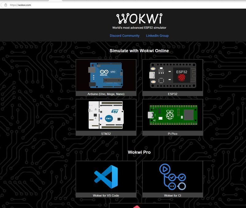
I am going to use wokwi and arduino to simulate simply circut of button that wil turn on and off a led diode.
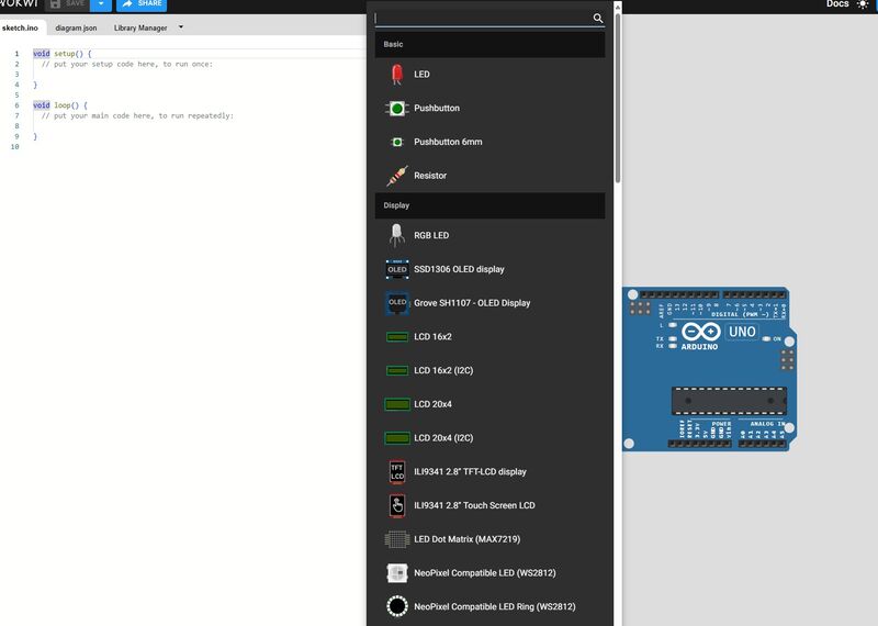
First thing to do is going to Wokwi and sett up the circut
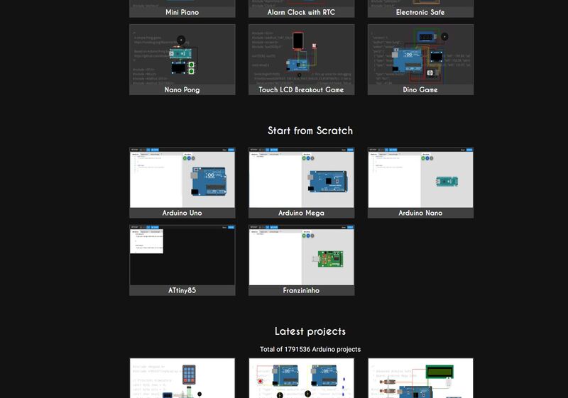
Then i have to open wokwi and choice some board that i am going tuo use, i choice Arduino uno that is the bord on the picture to the right here above.
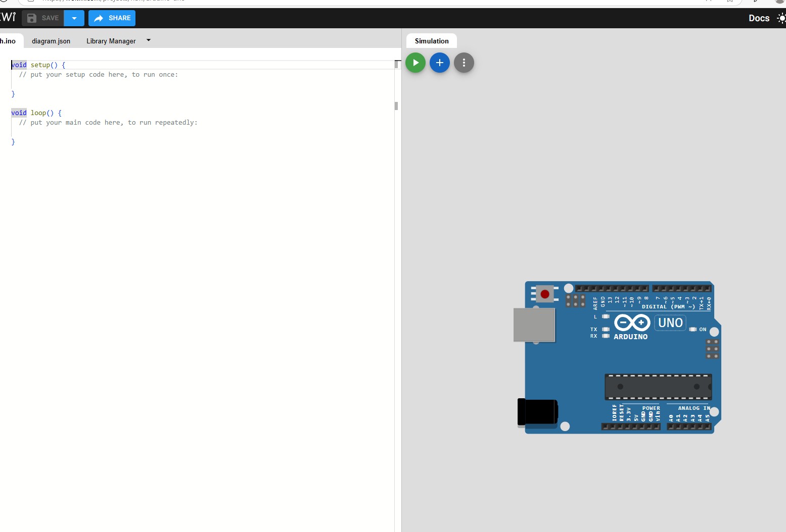
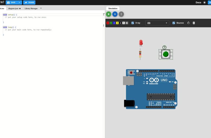
then i have to find the componentes that i am going to use that is: - - LED - Resistor 330ohm - Resistor 1kohm - Button That 1K resistor is for connecting the pullup function on the button i later found out that the circut also worked whit out the 1Kohm resistor
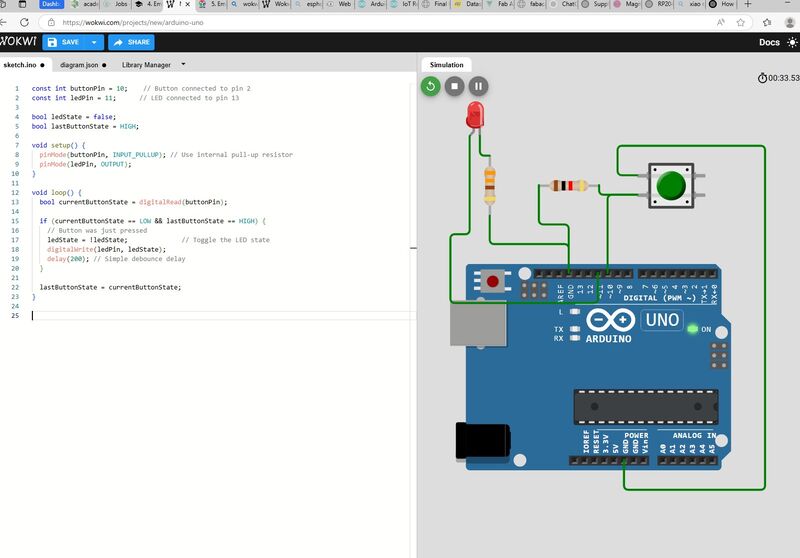
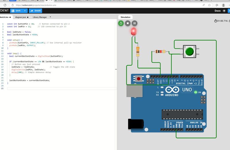
Here we have picturee of the circut connected and programmed on the picture to the rigt we then see ligth showing the circut is working here is the program file
And the finally some video showing it´s all working great